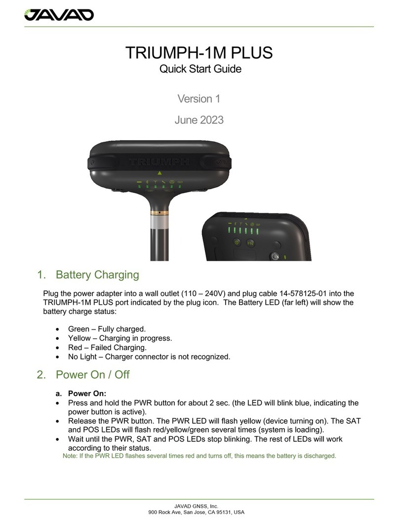
Javad TRIUMPH-1M Plus User manual

JAVAD GNSS, Inc.
900 Rock Ave, San Jose, CA 95131, USA
TRIUMPH-1M Plus
User Manual
Version 4
July 2023

Page 2of 26
Table of Contents
1. TRIUMPH-1M Plus Overview.............................................................................................. 4
1.1. Shipping Contents........................................................................................................ 4
1.2. Appearance ................................................................................................................. 4
1.3. Ports and Buttons ........................................................................................................ 6
1.4. Wireless Interfaces ...................................................................................................... 6
1.5. LED’s ........................................................................................................................... 7
1.6. Options Authorization File (OAF) ................................................................................. 8
1.7. Firmware Update ......................................................................................................... 9
1.8. Mounting...................................................................................................................... 9
2. Port Connections................................................................................................................10
2.1. USB ............................................................................................................................10
2.2. Bluetooth ....................................................................................................................10
2.3. Wi-Fi ...........................................................................................................................10
2.4. Power Management....................................................................................................11
2.5. External UHF Radio Connection .................................................................................12
3. Software Interfaces ............................................................................................................13
3.1. NetView&Modem ........................................................................................................13
3.2. Javad Mobile Tools (JMT)...........................................................................................13
3.3. Field Survey................................................................................................................14
4. RTK Configuration..............................................................................................................15
4.1. RTK Setup for both Base and Rover ...........................................................................15
5. Setup and Survey...............................................................................................................17
5.1. Measure Antenna Position ..........................................................................................17
5.2. Collect Data ................................................................................................................18
5.3. Static Survey for Base Stations...................................................................................19
5.4. Kinematic Survey for Rover Stations...........................................................................20
5.5. RTK ............................................................................................................................20
5.6. File Maintenance.........................................................................................................21
6. Mechanical Properties........................................................................................................22
7. Troubleshooting .................................................................................................................23
7.1. Check this First ...........................................................................................................23
7.2. FAQ ............................................................................................................................24
8. User Information ................................................................................................................26
8.1. Safety Information.......................................................................................................26

Page 3of 26
8.2. Usage and Safety .......................................................................................................26
8.3. Radio Frequency Exposure.........................................................................................26
8.4. Warranty .....................................................................................................................26
8.5. Technical Support .......................................................................................................26

Page 4of 26
1. TRIUMPH-1M Plus Overview
Ensure that all of the following items have been included with your Triumph-1M Plus device
shipping pack. If anything is missing, contact your dealer as soon as possible.
Check all documentation. Read the documentation that came with the equipment and keep it for
future reference. Check all documentation. Read the documentation that came with the receiver
and keep it for future reference.
1.1. Shipping Contents
The TRIUMPH-1M Plus is shipped with the items shown in the table below.
Description
Part Number
Triumph-1M Plus GNSS Receiver
01-630100-21
Triumph-1M Plus Pole Adaptor
10-590293-01
Extension Cable SAE/SAE (1.8m)
14-578102-01
Power Cable, 1-3.5 plug / SAE (0.33m)
14-578125-01
AC Power Cable, C13/C14, 6 ft.
14-578153-01
USB Cable, A / micro-B, 1m
14-578156-01
JAVAD Transport case for Triumph-3 series
20-720300-01
Power Supply/Charger 24VDC 90W
22-570106-20
AC Power Adapter*
23-590029-0X
*AC Power adapter depends on the AC socket type per country
1.2. Appearance
Figure 1: Front View

Page 5of 26
Figure 2: Back View
Figure 3: Bottom View

Page 6of 26
1.3. Ports and Buttons
The device has just two physical interfaces (ports) on the back panel of the unit. Both interfaces
are closed with protective rubber cover. It is strongly recommended to keep them closed while
you are not using it.
1.3.1. Ports:
•USB type Micro B (High Speed).
•Power port type 1-3.5 DC power input.
Note: Please use only the power charger system packed with the device. Using any other type of power charger can
cause damage.
1.3.2. Buttons
•Power Button (PWR).
•Record Button (FN).
Note: REC button is one programmable button. In further instructions it is called the FN button (“Function”).
1.4. Wireless Interfaces
There are two antennas (Bluetooth and Wi-Fi) placed under the housing cover. In addition, the
cellular and UHF antennas are located within the provided Triumph-1M Plus Pole Adaptor (P/N:
10-590293-01) and are shown below.
Figure 4: Wireless Interfaces

Page 7of 26
1.5. LED’s
The TRIUMPH-1M Plus has 6 RGB LEDs on the front panel.
Power (PWR) LED (no external charge):
•Green – Battery power level >30%.
•Yellow – Battery power level from 15% to 30%.
•Red – Battery power level <15%.
•Blue – Instantly flashes while pressing PWR button.
•No Light – Device is off.
Power (PWR) LED (with external charge):
•Green – Device is fully charged.
•Yellow – Device is charging.
•Red – Failed charging.
Bluetooth (BT) LED:
•Blue – Bluetooth is on, connection established (for multiple SPP connection Blue LED is
flashing every 15 sec.).
•Red – Bluetooth is on, no connection.
•No Light – Bluetooth is off.
Wi-Fi (WLAN) LED:
•Green – Wi-Fi is on, connection established.
•Red – Wi-Fi is on, no connection.
•No Light – Wi-Fi is off.
Satellite (SAT) LED:
•Green – More than 8 usable satellites.
•Yellow – 5 – 8 usable satellites.
•Red – 1 – 5 usable satellites.
•No light – No satellites tracked.
Position (POS) LED:
•Green – Position type matches requested type.
•Yellow – Position type is less than requested type (e.g., current position computed is
standalone when RTK fixed positioning mode is configured).
•Red (flashing) – No position.
•Red/Yellow/Green flashing one-by-one – SV tracking option is not active.
Record (REC) LED:
•Green – Log file is being recorded.
•No Light – No file is being recorded by now.
The usual stable tracking/positioning indicator would be shown by a constant green light for
<SAT> LED and a flashing green light for <POS> LED.
If no satellites are being tracked (impossible to compute position), the <SAT> LED will be off
and the <POS> LED with flash red.

Page 8of 26
1.6. Options Authorization File (OAF)
JAVAD GNSS issues an Option Authorization File (OAF) to enable specific purchased options.
An Option Authorization File allows customers to customize and configure the Triumph-1M Plus
receiver according to their needs, thus only purchasing those options needed.
Typically, all Triumph-1M Plus receivers are shipped with a temporary OAF that allows the
receiver to be used for a predetermined period. When the receiver is purchased, a new OAF
activates purchased options permanently. Receiver options remain intact when clearing the
NVRAM or resetting the receiver.
For a complete list of options and their details, visit the JAVAD GNSS website.
You can check the status of your receiver’s options and load any new OAFs via
NetView&Modem software. Connect your receiver and computer, launch NetView&Modem
application, and establish connection between NetView and receiver. For more details, see the
NetView&Modem user manual.
In “Options” tab, the list of options available and their status are shown:
•Option name / Description – A name/description of the option.
•Current – Shows if the option is in force at the present or not.
•Purchased – If the option is purchased or not.
•Leased – If the option is leased or not.
•Date – The date the leased option will be disabled, if applicable.
Figure 5: NetView&Modem – Options

Page 9of 26
1.7. Firmware Update
Use NetView&Modem to check the receiver’s firmware version. Information about the firmware
version is shown on the main tab once connected. On the right from the receiver picture appears
the information about the receiver including receiver model, ID, firmware version.
Base and Rover receivers must be loaded with the same firmware version. to ensure the
receiver has the most recent updates, use either the Stable or Latest firmware version, available
for download from the JAVAD GNSS website.
To load new firmware using NetView&Modem on a main tab click on the Update Firmware.
Select the file with the latest firmware. The firmware will be uploaded automatically, and the
receiver will reboot.
Figure 6: NetView&Modem - Update Firmware
1.8. Mounting
The TRIUMPH-1M Plus Receiver can be mounted using the standard 1/4 thread hole on the
bottom of the unit. Also, there is a 1/4" to 5/8” thread adapter available in the shipping kit for the
standard surveying 5/8” pole thread.

Page 10 of 26
2. Port Connections
2.1. USB
The USB cable (P/N: 14-578156-01) supports a connection of any USB 2.0 (high speed) type
level cable and above. The USB cable provides a connection from the TRIUMPH-1M Plus to a
PC (or any other device with USB connection support). It is possible to establish other
connection types using virtual connection ports where physically it will remain the USB cable:
•Serial (COM) port A (for Windows OS devices).
•Serial (COM) port B (for Linux OS devices).
•Ethernet (Ethernet over USB protocol).
For NetView&Modem on a Linux OS, the default connection type is serial (COM – Serial A/B).
The physical parameters of the connection types are all via the USB connection.
2.2. Bluetooth
The TRIUMPH-1M Plus can establish a Bluetooth connection via Serial Port or PAN Profile. To
turn on Bluetooth, use NetView&Modem:
•Pair the TRIUMPH-1M Plus to PC.
•Connect NetView&Modem to TRIUMPH-1M Plus using the assigned Serial (COM) port.
•Go to the Parameters – Ports – Bluetooth section in NetView&Modem.
•At the Mode dropdown, select ‘ON’.
•Press OK to reboot the device with Bluetooth on.
The device has two Bluetooth serial ports (A and B). Each port can have modes selected (which
port uses the connection) separately or automatically (if both ports are on). To connect external
Bluetooth devices to the TRIUMPH-1M Plus, perform the following steps:
•Establish or review Bluetooth identification and password.
•On the external device, find the TRIUMPH-1M Plus ID in listed devices and select it.
•Enter password and connect.
To establish a PAN connection, first connect to the device and use the function ‘internet access’
on the external device. The TRIUMPH-1M Plus will generate an IP address for the external
device.
2.3. Wi-Fi
To establish a Wi-Fi connection to the TRIUMPH-1M Plus, perform the following steps:
•Connect the device to a PC using NetView&Modem.
•Go to the Parameters – Connections – WLAN section.
•At the Mode dropdown, select the mode type and confirm to reboot the device (if
needed).
•For connecting to the device (server mode), use the corresponding block of parameters
with SSID and password. Connect to the unit using an external Wi-Fi device.
•For connecting to the device (client mode), use the corresponding block of parameters
with SSID and password. Fill in the SSID and password of an operating WLAN network.
For more details, please see the NetView&Modem User Manual.

Page 11 of 26
2.4. Power Management
The TRIUMPH-1M Plus receiver has an internal (2S3P) battery pack. The battery pack features:
•Power voltage up to 8.3V.
•Internal Fuel Gauge system that prevents any occasions that can damage the battery
and device (shortcuts, overheating, etc.).
•Battery lifecycle – about 25 working hours (all systems on).
•Battery charge input – up to 30V.
2.4.1. Battery LED
The battery LED shows the status of the internal battery pack.
Green LED
Yellow LED
Red LED
>30% Power
15% – 29% Power
<15% Power
2.4.2. Power On / Off
To turn the device on:
a. Press and hold the PWR button for about 2 sec. (the LED will blink blue; this means the
power button is active).
b. Release the PWR button. The PWR LED will flash yellow (device turning on). Then SAT
and POS LEDs will flash red/yellow/green several times (system is loading).
c. Wait until the PWR, SAT and POS LEDs stop blinking. The PWR will constantly stay with
the color from the table above. The rest of LEDs will work according to their status.
Note: If after pressing PWR button the PWR LED flashes several times red and turns off, this means the battery is
discharged.
To turn the device off:
a. Press and hold the PWR button for about 2 sec. (the LED will flash yellow).
b. The device will turn off by itself.
To maximize battery life, use the JAVAD supplied power cables and charger shipped with the
unit.
2.4.3. Battery Charging
The supplied power adapter (P/N: 22-570106-01) and power cable (P/N: 14-578125-01) can be
plugged into a wall outlet and into the TRIUMPH-1M respectively. A full charging cycle is less
than 9.5 hours. The internal battery pack charge status is shown on battery LED:
•Red – Less than 30% charge.
•Yellow – 15-29% charge.
•Green – 30-100% charge.
Note: The internal battery pack cannot be overcharged.

Page 12 of 26
2.5. External UHF Radio Connection
The TRIUMPH-1M Plus does not have an internal UHF radio. It is possible to send and receive
data using an external UHF radio and a TRIUMPH-1M Plus. To do this, perform the following
steps:
•Connect the device to a PC using NetView&Modem (any connection type except
Bluetooth).
•Configure the external UHF radio by powering it on and connecting it to
NetView&Modem.
•Turn Bluetooth on for both devices (if needed).
•Connect the TRIUMPH-1M Plus to the external UHF radio using a Bluetooth SPP
connection.
•In the TRIUMPH-1M Plus NetView&Modem connection, go to Parameters – Ports – UHF
section and set the mode of the UHF device as needed (depending on base or rover
applications).

Page 13 of 26
3. Software Interfaces
NetView&Modem software can configure the TRIUMPH-1M Plus for various field applications.
The TRIUMPH-1M Plus can be easily operated in the field using data collection software:
•Field Survey – Window OS devices.
•Javad Mobile Tools – Android OS devices.
These are detailed below.
3.1. NetView&Modem
NetView&Modem can set all the parameters available on the TRIUMPH-1M Plus for various field
applications. The device can be connected to the PC using USB, Wi-Fi, or Bluetooth. For more
information, see the NetView&Modem User Manual.
3.2. Javad Mobile Tools (JMT)
The TRIUMPH-1M Plus can be easily operated over Bluetooth in the field using the Javad
Mobile Tools (JMT) android app.
Figure 7: Javad Mobile Tools (JMT)
For more information, see the Javad Mobile Tools User Manual.

Page 14 of 26
3.3. Field Survey
The TRIUMPH-1M Plus can be operated over Bluetooth in the field using the Field Survey
Windows OS app.
Figure 8: Field Survey
For more information, please see the Field Survey User Manual.

Page 15 of 26
4. RTK Configuration
Configuring the TRIUMPH-1M Plus for Base and Rover RTK operation can be performed in
NetView&Modem.
4.1. RTK Setup for both Base and Rover
The following Base and Rover configurations are the most common for field applications.
Parameter
Base
Rover
Implicit Message Output
Period
15 Seconds
Elevation Mask
15 Degrees
File Name Prefix
Enter a unique ID, such as the last 3 digits of the
receiver’s serial number. By default, the prefix is
‘log’.
REC (FN) Key Mode
Starts / Stops the data logging when FN button is
pressed
Initial Dynamic Mode
-
Select Dynamic
•Connect the receiver and computer, start NetView and establish the connection as
described above.
•Click Receiver>Parameters on the left panel.
•In the General tab check antenna status of the parameter Antenna Input to be Internal
(External antenna input is not available for Triumph-3NR).
•Open the Log files tab and then TriPad tab and set the following parameters, click Apply.
•Open the Positioning tab and set the Elevation mask (default: 15 Degrees).
To configure a Base station, open the Base tab and set the following parameters:
•Antenna Phase Center Position (APC) – Enter Latitude, Longitude, and Altitude
(ellipsoidal) values. This can be manually entered or can be auto filled by the current
receiver position using the ‘Get From Receiver’ button.
•Restart the receiver.
To configure a Rover, open the Positioning tab and set the Position Computation Mode:
•PD – Carrier phase differential (RTK) with fixed ambiguities

Page 16 of 26
Open the Rover tab and set the following parameters:
•RTK Position Computation Mode – Select ‘Extrapolation’ for float RTK (kinematic) or
Delay for fixed RTK (static). If ‘Extrapolation’ is selected, the rover will extrapolate the
base station’s carrier phase measurements when computing the rover’s current RTK
position. If ‘Delay’ is selected, the rover will not extrapolate the base station’s carrier
phase measurements when computing the rover’s current RTK position. Instead, the
RTK engine will compute either a delayed RTK position (for the epoch to which the
received correction message corresponds) or the current standalone position (while
waiting for new correction messages from the Base).
•Confidence Level for Ambiguity – This governs the process of the RTK engine fixing
integer ambiguities. The RTK engine uses the ambiguity fix indicator to determine
whether to fix ambiguities or not. Low (95%), Medium (99.5%), and High (99.9%) specify
the confidence intervals. The higher the confidence interval, the longer the integer
ambiguity search time and higher precision.
For RTK surveys, open the Ports tab and set the parameters according to the table below:
Parameter
Base
Rover
Input
-
The same correction
type as the Base
Output
Select correction type
-
Period (sec)
Set the period of
correction output
-
Baud Rate
Baud rate for the corresponding receiver port
RTS/CTS
Enable
Open the Advanced tab – Multipath Reduction and enable ‘Carrier Multipath Reduction’ on Base
and Rover for RTK mode.
•Click ‘Apply’ to save the changes to the receiver and close the window. The receiver
configuration will remain until changed further or when the NVRAM is cleared (and
restore the factory default configuration).

Page 17 of 26
5. Setup and Survey
After configuring the receiver(s) for surveying, each receiver needs to be setup up and the
receiver’s height measured for the survey to begin. The MinPad provides quick access for
logging data, changing receiver modes, and viewing general data logging and satellite
information during a survey.
A typical GPS survey system consists of a Base station set up over a known point and a Rover
receiver set up to be a mobile data collector. After setting up the Base and Rover receivers, the
antenna height must be measured.
Before collecting data, make sure the Base and Rover receivers contain a current almanac and
current ephemeris data.
The Base station must be set up, logging, and transmitting data before setting up the Rover
receiver. Receiver setup for either post-process or RTK surveys is the same.
5.1. Measure Antenna Position
The location of the antenna relative to the point being measured is very important for both
surveys in which the elevation of the points is important and in surveys for horizontal location
only. Horizontal surveys are often larger in area than can reliably fit on a flat plane, therefore the
antenna adjustment must be done in three dimensions and then projected onto a two-
dimensional plane.
The receiver calculates the coordinates of the antenna’s phase center. To determine the
coordinates of the station marker, the user must specify the following:
•Measured height of the antenna above the station marker.
•Method of measuring the antenna height.
•Model of the antenna used.
Antennas have two types of measurements:
•Vertical – measured from the marker to the antenna reference point (ARP) located on
the bottom of the receiver at the base of the mounting 1/4 thread.
•Slant – measured from the marker to the lower edge of the antenna slant height measure
mark (SHMM) located on the side panel of the receiver (green triangle).
The point at which surveying with GNSS measures is called the Antenna Phase Center (APC).
This is analogous to the point at which a distance meter measures in a prism. A user must enter
the prism offset to compensate for this point not being at the physical surface of the prism. For a
GNSS antenna, the offset is entered depending on the type of measurement taken.
To prevent tilting of the receiver, you can use embedded IMU module, which determines
deviations from the vertical (relative Earth surface) in real time.
For vertical, the offset is simply added to the measured vertical height to produce a “true”
vertical height. For example, surveying poles can be set on specific height. In this case the “true”
height will be summary of pole length set and adapter height (if you use one).
For slant height, the vertical height must first be calculated using the radius of the antenna, then
the offset can be added.

Page 18 of 26
The offsets are different because of the difference in location between the slant measuring point
and the vertical measuring point.
Measure the antenna height to the control point or marker edge, either the slant height or the
vertical height.
Record the antenna height, point name, and start time in the field notes.
5.2. Collect Data
See the remaining sections in this chapter for more information on collecting data.
•Turn on the receiver.
•Once the receiver has locked on eight or more satellites, the SAT light will turn green.
•The red color of POS LED indicates that the receiver has not solved a position. Four or
more satellites provide optimal positioning.
•Once the red POS LED is green, the receiver has a position and surveying can begin;
wait for green light before beginning data collection. This ensures that the receiver has
the correct date and time and is locked on to enough satellites to ensure good quality
data.
•The process of locking on satellites normally takes less than one minute. In a new area,
under heavy tree canopy, or after resetting the receiver, it may take several minutes.
•To begin collecting data, press and hold the Record (FN) button (for more than one
second and less than five seconds).
•Release the Record button when the REC (recording) LED turns green. This indicates
data collection has started. The REC LED blinks each time data is saved to the internal
memory.
When finished, press, and hold the Record button until the REC LED light goes out.
To turn off the receiver, press and hold the power button until all lights go out, then release.

Page 19 of 26
5.3. Static Survey for Base Stations
Static surveying is the classic survey method, well suited for all kinds of baselines (short,
medium, long). At least two receiver antennas, plumbed over survey marks, simultaneously
collect raw data at each end of a baseline during a certain period. These two receivers track four
or more common satellites, have a common data logging rate (5–30 seconds), and the same
elevation mask angles. The length of the observation sessions can vary from a few minutes to
several hours. The optimal observation session length depends on the surveyor’s experience as
well as the following factors:
•The length of the baseline measured.
•The number of satellites in view.
•Satellite geometry (DOP).
•The antenna’s location.
•The ionospheric activity level.
•The types of receivers used.
•The accuracy requirements.
•The necessity of resolving carrier phase ambiguities.
Generally, single-frequency receivers are used for baselines whose lengths do not exceed 15
kilometers (9.32 miles). For baselines of 15 kilometers or greater, use dual-frequency receivers.
Dual-frequency receivers have two major benefits. First, dual frequency receivers can estimate
and remove almost all ionospheric effect from the code and carrier phase measurements,
providing much greater accuracy than single-frequency receivers over long baselines or during
ionospheric storms. Secondly, dual-frequency receivers need far less observation time to reach
the desired accuracy requirement.
After the survey is complete, data the receivers collect can be downloaded onto a computer and
processed using post-processing software (for example, JAVAD GNSS Justin).

Page 20 of 26
5.4. Kinematic Survey for Rover Stations
In a kinematic, stop and go survey, the stationary receiver (Base station) is set up at a known
point such as a survey monument, or an unknown point. The receiver continually tracks
satellites and logs raw data into its memory. The Rover receiver is set up at an unknown point
and collects data in static mode for 2 to 10 minutes. When finished, assign the Rover to
kinematic status, and move to the next survey point. At this point, and each subsequent point,
the receiver is changed to static mode to collect data. So, while moving, the Rover is in
kinematic mode, and while collecting data, the Rover is in static mode.
•Set up the Rover at an unknown point and press the Power button.
•Allow the Rover to collect static data for two to ten minutes. The REC LED will be yellow.
•Check the SAT light for satellites tracked.
•When finished, press the Record (FN) button for less than 1 second to assign the Rover
to kinematic.
•Move the Rover to the next location (survey point) and press the Record (FN) button for
less than a second to collect the data in static mode for two to ten minutes.
•Repeat the two previous steps until all points have been surveyed. The occupation time
for the points depends on the same factors as for the static survey method.
When finished, press the Record (FN) button for one to five seconds to stop logging data. Turn
off the Rover if needed. This method of GNSS survey allows the operator to reduce the point
occupation time, thus permitting field crews to survey many more points compared to the other
methods available.
5.5. RTK
With RTK surveying, as with kinematic surveying described above, one receiver serves as the
reference station and conducts observations with its antenna affixed to a stationary tripod or
some other device. The other receiver functions as a rover and conducts observations (using an
antenna) affixed to a mobile pole and moved to observation points.
Unlike post-processed kinematic surveys, RTK surveys utilize a communications link between
the Base and Rover. Using a radio modem link, the Base receiver transmits its measurement
and location data to the Rover receiver. The Rover, based on the transmitted data and its own
observation data, immediately conducts a baseline analysis and outputs the results.
Usually, the receiver will start to output the coordinates of the antenna’s phase center along with
the solution type within 10–30 seconds. However, UHF radios and GSM phones may take as
long as 60 seconds to synchronize. The geodetic coordinates displayed on the Location tab are
always computed in WGS84 and have four solution types.
•Standalone – where the receiver computes 3D coordinates in autonomous mode without
using differential corrections.
•Code differential – where the Rover receiver computes the current relative coordinate in
differential mode using only pseudo ranges.
•RTK float – where the Rover receiver computes the current relative coordinates in
differential mode using both pseudo ranges and phases; however, with a float solution,
the phase ambiguity is not a fixed integer number, and the “float” estimate is used
instead.
Other manuals for TRIUMPH-1M Plus
2
Table of contents
Other Javad Antenna manuals
Popular Antenna manuals by other brands

Bonito
Bonito NTi MegActiv MA305FT operating manual

Intellian
Intellian i3 Installation and operation manual

Ferimex
Ferimex ISM Antennas instructions

Velleman
Velleman ANTDVBT quick start guide

Tarheel Antennas
Tarheel Antennas Little Tarheel HP instruction manual

tactio
tactio LAXO-AN-PG21 installation guide