PORT 2
PERIPHERALS
FAE/
ROBOT
PORT 1
DDU
www.jbctools.com
P305
Configuration
Switch
SUPPORT
CONNECTION PEDAL
STATION TOOL
1 2 3
SW1
8
Tool
Control Unit
1
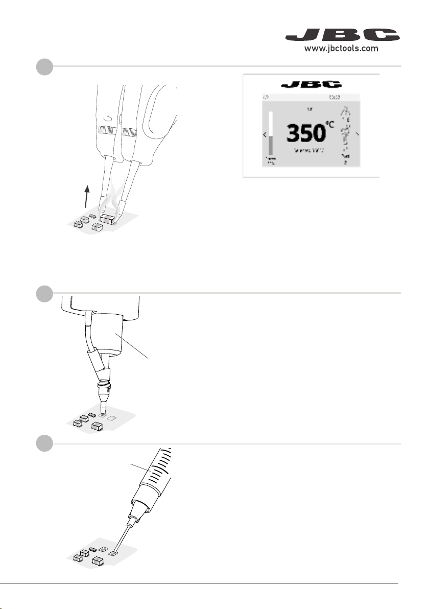
Example:
Chip Compoments Rework Process using Tweezers and Pedal
Adapter for P305
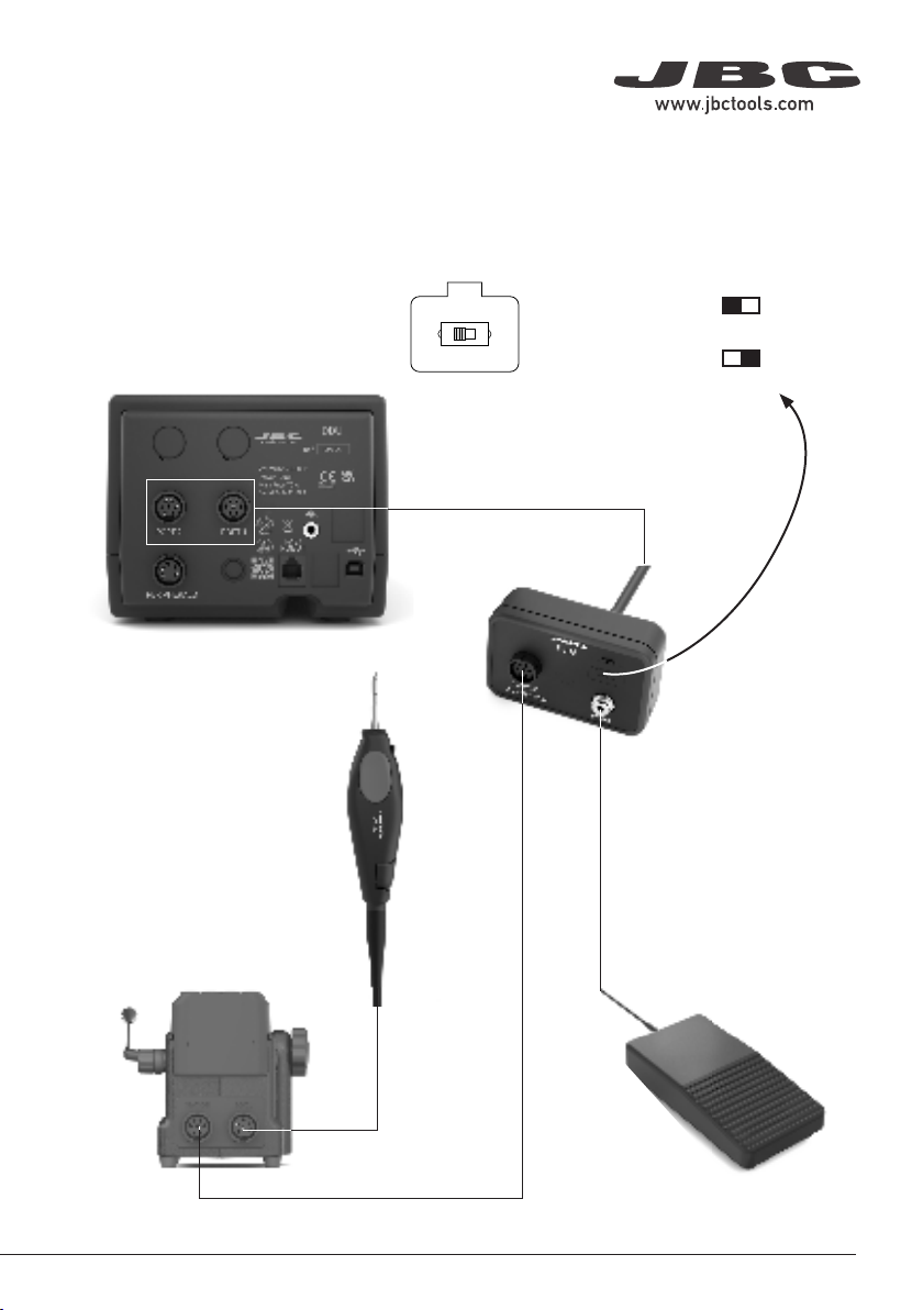
Connections
Connect pedal P305 to its adapter and then the adapter
to the control unit port. The tool must be connected to
its sand and the stand to the pedal adapter.
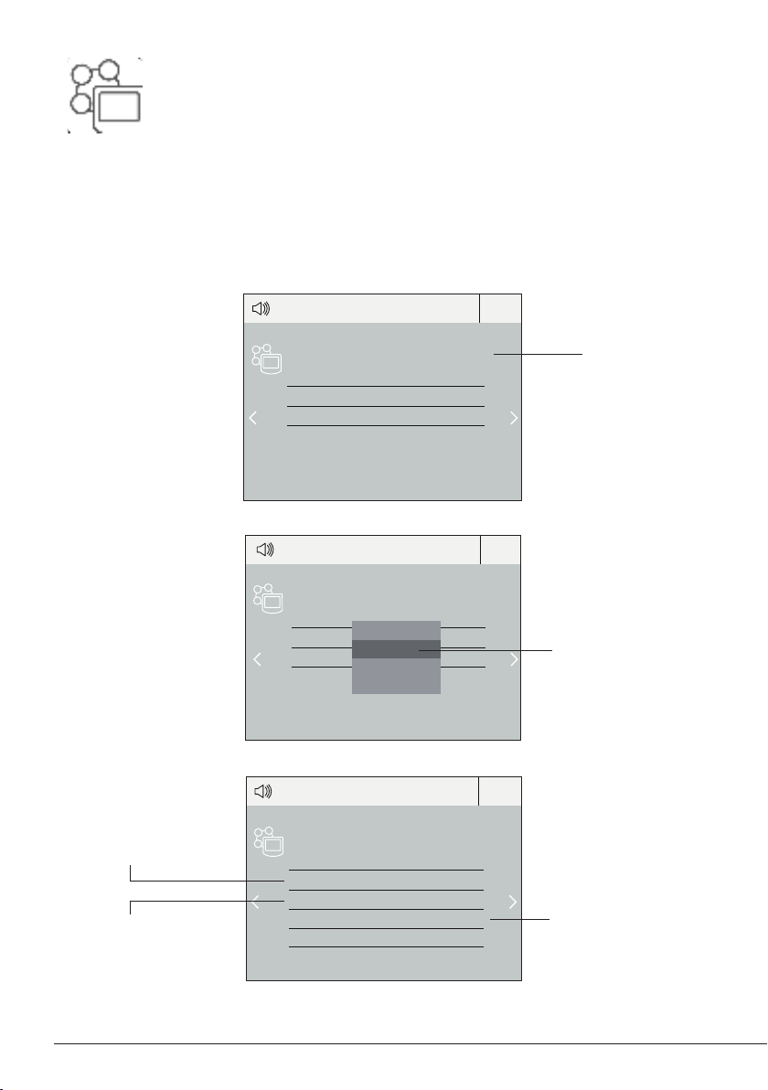
In the peripherals menu for the “Pedal Activation Mode”
choose between “pressed” and “released”.
Note: If working with P305 and its adapter, choose
the pedal funtionality at the adapter switch like shown
beside.
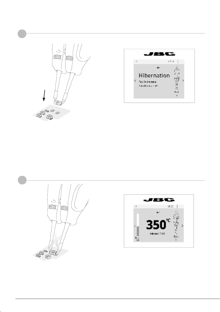
The Pedal is frequently used to rework components with tweezers.
AN115 JBCs adjustable nano tweezers is the most effective tool for desoldering chip components
but also it facilitates its rapid placement and soldering by using P405 pedal connected to JBC´s NAS
station.
Stand
Pedal
P305
Pedal Kit
for Control Units
Adapter Switch
To reverse the pedal functionality
choose:
NO > press to work
(normally open)
NC > release to work
(normally closed)
Adapter Switch