JBL GT0-804EZ User manual

®
bvHARMAN
GT0-804EZ/GT0-504EZ
power amplifier
OWNER'S MANUAL

2
WHY YOU SHOULD
PAY
ATTENTION TO THIS OWNER'S MANUAL
The performance of your vehicle's audio system depends as much on quality installation and setup as it does on
quality gear. Of course, these new
JBL
® GTO amplifiers are bulletproof perfo
rm
ers that are built using the highest
quality components, and will outperform any competing prod
uct
on
the
test bench.
To
make sure you extract all
the performance possible from your new amp, whether you install it yourself or have a professional install it for you,
we've incorporated some new features that make se
tup
simple and precise and ensure you get
al
l the power and
performance you've paid for.
WHAT MAKES THESE AMPLIFIERS DIFFERENT
All amplifiers include some signal processing functions, level setting controls and other switches and
co
nnectors that
make it possible to hook the amp up
to
just about any existing system. However, with many amplifiers, considerable
technical expertise
is
required
to
make the best use
of
those connectors, switches and controls
to
get powerful noise-
free sound.
JBL
GTO amplifiers include Simple Setup designed
to
make it easy for you
to
get
all
the noise-free power
yo
ur
amp is capable
of
delivering.
WHAT MAKES INPUT SETUP EASY
GTO Amplifiers include adapters for connecting almost any analog signal and feature built-in Gain Indicator LEOs and
a setup CD that makes precision adjustment simple, no matter your level
of
experience. The setup
of
GTO amplifiers is
a little different than amplifiers you may have installed
in
the past, so please read this owner's manual before you
begin. If you're an experienced installer, skipping ahead is OK,
but
please
don't
skip Setup Procedure, on
page 8.
So we can better serve you should you require warranty
se
rvice, please retain your orig
in
al
sal
es
receipt and register
your
GT0-804EZ
or
GT0-504EZ
online at www.jbl.com.
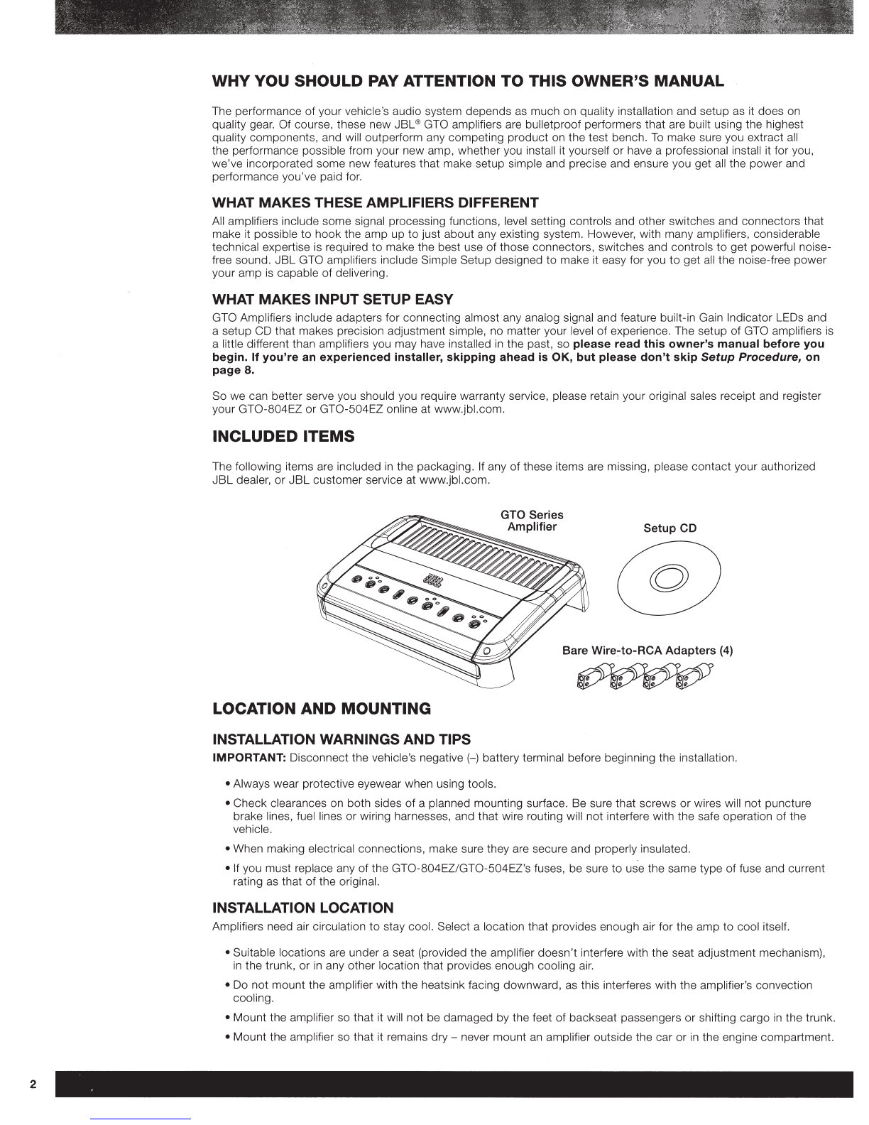
INCLUDED ITEMS
Th
e following items are
in
cluded
in
the packaging. If any
of
these items are missing, please contact your
au
thorized
JBL
dealer, or JBL customer servi
ce
at www.jbl.com.
Setup CD
Bare
Wire~to-RCA
Adapters (4)
LOCATION AND MOUNTING
INSTALLATION WARNINGS AND TIPS
IMPORTANT: Disconnect the vehicle
's
negative(-) battery terminal before beginning the installation.
• Always wear protective eyewear when using tools.
• Check clearances on both sides of a planned mounting surface. Be sure that
sc
rews or wires wi
ll
not puncture
br
ake lines, fuel
lin
es or wiring harnesses, a
nd
tha
t wire routing will
not
interfere with the safe operation
of
the
vehicle.
•
Wh
en making elect
ri
cal
co
nnection
s,
make sure they are secure and pro
per
ly insulated.
• If you must replace any
of
the GT
0-804E
Z/GT0 -504EZ's fuses, be sure to use the same type of fuse and curre
nt
rating as that
of
the origina
l.
INSTALLATION LOCATION
Amplifiers need air circ
ul
ation to stay coo
l.
Select a location th
at
pr
ovides enough air
for
the a
mp
to
coo
l itself.
• Suitable locations are under a seat (provided the amplifier doesn't interfere with the seat adjustment mechanis
m)
,
in
the trunk, or
in
any
ot
her l
oca
tion that provides enough c
oo
ling air.
• Do not mount the amplifier with the heatsink f
ac
ing downward, as this
in
terferes with the ampl
if
ier's convection
coo
ling.
• Mount
th
e amplifier so that it will not be damaged by the feet of backseat passengers or shifting car
go
in
the trunk.
• Mount the amplifier so that it rema
in
s dry -never mount an amplifier outside the car or in
th
e engine
co
mpartment.

MOUNTING THE AMPLIFIER
NOTE:
You
may find it more convenient
to
make
all
of the connections to the amplifier
bef
o
re
you permanently mount
it to the vehicle.
Before mounting the amplifier you must remove the two end caps
to
expose the mounting holes and the connections.
Using a Phillips screwdriver, remove the attachment screws and then the end caps, as shown
in
the illustration.
Pu
t
the screws
in
a safe place, so you can use them
to
reattach the end caps after you have made all the
co
nnections
to
the amplifier.
NOTE:
Before you permanently mount the
amp
lifier, read
Auto
Turn-On Switch, below,
to
determine the setting of the
switch, which
is
located on the amplifier's bottom panel.
1.
Sele
ct
a suitable mounting location as described above.
2. Using the amplifier as a template, mark the l
oc
ations of the mounting holes on the mounting surface.
3.
Drill pilot holes
in
the mounting surface.
4.
Attach the amplifier
to
the mounting surface with four appropriate mounting screws
of
your own choice. We
suggest using #8 Phillips-head sheet metal
sc
rews. Make sure the amplifier
is
mounted securely.
CONNECTIONS
IMPORTANT:
Di
sconnect the
ve
hi
cle's negati
ve(
-)
ba
tt
ery terminal before beginning the insta
ll
at
ion.
If you have not al
rea
dy
do
ne so, remove the
tw
o end caps that cover the amplifier
's
co
nn
ectors as expla
in
ed
in
Mounting the Amplifie
r,
above. T
hi
s w
ill
provide easier access to a
ll
of the amplifier
's
co
nnectors.
AUTO TURN-ON SWITCH
No
rem
ote turn-on
co
nnection is necessa
ry
because G
TO
amplifiers include signal-sensing turn-on, which will turn
the amplifier on when it receives an audio sign
al
at any
of
its input connectors. The amplifier will automatically turn off
approximate
ly
fi
ve
minutes after the input signal ceases.
If your audio system
's
source unit
in
clud
es
a remote turn
-o
n wi
re
and you would prefer to u
se
it. the amplifier
will
se
nse that you've u
se
d a remote turn-on wire and that connection will override the signal-sensing turn-on. If
necessary, you
ca
n defeat the signal-
se
nsing turn-on circuit
by
mo
vi
ng the Auto Turn-On switch to the "Off" position.
3

4
CONNECTING
THE
POWER
AND
GROUND
The GTO se
ri
es amplifiers are capable
of
delivering extremely high
po
wer levels, a
nd
require a h
ea
vy-du
ty
and
reliable connection
to
the vehicle
's
el
ectrical system to achieve optimal performance. Please adhere to the following
instructions carefully.
Using
the
Connectors
GTO series amplifiers use the same type of screw terminals for power and speaker
co
nnections. This type of terminal
is easy
to
use, provides superior current transfer and all
ow
s the easy connection
of
large-gauge wire.
To
use the
co
nnectors, use a Phillips screwdriver
to
loosen the
connector'
s set
scr
ew, insert
th
e bare wire and tighten
the set scr
ew
to
secure the wire in the connector.
Ground Connection
Loosen
Screw
,
:
~~
:
C:.
.
Insert Tighten
Wire Screw
Connect a w
ir
e (minimum
SAWG-
8.4mm2-for the
GT
0 -804EZ; minimum 1
OAW
G -
5.3mm
2-for the
GT0-504E
Z)
from the amplifier's GND terminal directly
to
a solid point on the vehicl
e'
s chassis. For a
go
od connection, use
sa
ndp
aper to clear the paint from the metal surfa
ce
at this chassis l
ocat
ion. Use a star-type l
oc
k washer
to
secure the
wi
re
's conn
ec
tion.
Audio System Head Unit
Power
Connectors
o o Remote Turn-On (optional)
~~~
8( )
:Sg
I;
~
<
~~
;
~
·-
'~c
,
iioWi
OK· •• ;
C:.
,-
=
~
0
o o
ooooo
a o
~
#
18
AWG (0-82mm2) Wire
+12V
Chassis Ground
(bare metal)
1
~
#8AWG (13.2mm2) Wire -
GT0-804EZ
t
~
#1
OAWG
(5-3mm2) Wire -
GT0-504EZ
18"
(46cm)
+
~
#8AWG (13_2mm2) Wire -
GT0-804EZ
~
#1
OAWG
(5-3mm2) Wire -
GT0-504EZ

Power Connection
1.
Connect a wire (minimum 8AWG -
8.4mm
2-for the
GT0-804EZ
; minimum 1
OAWG-
5.3mm2-for the
GT0-504EZ) directly
to
the battery's positi
ve(
+)
terminal.
2.
Install a fuse holder
for
a 50A fuse (GT0-804EZ) or 40A fuse (GT0-504EZ) on this wire within 18" (46cm)
of
the
battery's (+)terminal. Do
not
install the fuse
in
the holder at this time.
3.
Route this wire to the amplifier's location and connect it
to
the ampli
fi
er's +12V termina
l.
Be sure to use
appropriate grommets whenever routing wires through the firewall
or
other sheet metal. IMPORTANT: Failure to
adequately protect the positive wire from potential damage may result
in
a vehicle fire.
4. When you are finished routing and connecting this wire, install
the
appropriate fuse
in
the holder you installed near
the battery.
(GT0-804EZ-
50A fuse;
GT0-50
4
EZ-
40A fuse.)
SPEAKER
CONNECTIONS
Always connect
the(+)
terminal on the amplifier
to
th
e(
+)
terminal on the speaker and
the(-)
terminal on
the
amplifi
er
to the (-) terminal on the speaker.
Speaker
Connectors
· IMPORTANT: Make sure
the(+)
and (-) bare wires
do
not touch each other
or
the other terminal at both the amp
li
fier
terminals and speaker terminals. Touching wires can cause a short circuit that can damage the amplifier.
NOTE:
Th
e minimum speaker impedance for stereo operation is 2 ohms. The minimum speaker impedance f
or
b
ri
dged
operation is 4 ohms.
Stereo operation
• Connect the front speakers to the FL and
FR
(+)
and (-)terminals.
• Connect the rear speakers
to
the RL and
RR
(+)
and (-) terminals.
Front
Left
Speaker
Front
Right
Speaker
I I I I I I I I
~
-
~
~
~
-
~
-
-
~
-....___c:::~
~~~·~
~
'
-
'~
'
25A
25.'1
''
"'
0 ""
~D
[
QQ)Q
~
~~~
o.:;~
~
-
''"'
''X
Y l
.-
~
@
~
':1
FUSE
"" I
R
ear
Left
Speaker
Rear
Right
Speaker
I I ClPI I I I
c
r
~
I I
w
ww
.jbl.c
om
5

6
Bridged operation {three-channel system with
high-power
for
a subwoofer)
• Connect the left and right
sp
eakers
to
the
FL
and
FR
(
+)
and (-) terminals
• Connect the subwoofer
to
the RL
(+)
and
RR
(-) terminals. (The rear-channel Bass Boost control makes the rear
channels preferable for subwoofer connection. See Bass Boost, on page 1
0
.)
Left Speaker Right Speaker
I
I
c11~
I
I I
I
Y1~
I
I
'7P'
~
:.....,
--
mJji'
nn
•1
1'1'
0
QNO
[
[ooo
[J
"'"
""
Subwoofer
I
I I
I
r,-~~
NOTE: You can also run both pairs of left and
ri
g
ht
channels bridged f
or
a
hi
gh-p
ow
er
tw
o-channel system.
See Connecti
ng
the Inputs, on page 7, for information about connecting the inputs for bridged operation.
INPUT CONNECTIONS
The GT0-804EZa
nd
G
T0-504E
Z amplifiers have multiple input connectors with a routing switch that
in
creases
fl
exib
ili
ty, so you can use
th
ese amps
in
a variety of audio system
co
nfigurations.
ROUTING SWITCH
Front and Rear
lnpu
t
Co""ecto"'
~
r-
Connectors
Aux Out
w
..
r;m~yVold
r
=:.o
mrn
'"put j
Routing
Switch
L
fVEL
~
FROOr
RE~
II
-
I
IC
:L
00
1
10 1
•<
~ ~
~
~
0 I
,f-
:,oo
~:
o
~
~
~
~
~
-
..____
I
NPUT
--'h.
o.u•
our
[
~
The GTO amplifier routing switch lets you determine which
in
put connectors d
ri
ve the amplifier's various speaker
output
s:
• F: The front and rear speaker outputs are both fed by the
Fr
o
nt
Input connectors.
• F&
R:
The front speaker o
ut
p
ut
s are fed by the Front Input conn
ecto
rs; the rear speaker outputs are fed by the
Rear
In
put connectors.

CONNECTING THE INPUTS
Use RCA audio cables
to
connect source units with preamp-level outputs to the amplifier; use the supplied bare wire-
to-RCA adapters to connect
to
source units that don't have RCA output connectors.
Use a small
Ph
illips screwdriver to loosen the adapter's set screws and insert the speaker wires into the holes on the
back
of
the adapt
er.
Tighten the set screws
to
secure the wires.
Loosen
Screw Insert
Wire Tighten
Screw
Always connect the
(+)
speaker wire to the (+)terminal on the adapter and the (-) speaker wi
re
to
the (-)terminal on
the speake
r.
IMPORTANT:
Make sure the
(+)
and (-) bare wires do not touch each other. Touching wires can cause a short circuit
that can damage the source unit
or
the amplifier.
When you're finished, plug the adapter into the appropriate input connector on the amplifi
er.
• For bridged operation: Connect to the left input of each bridged channel pair.
AUX OUT CONNECTIONS
The Aux Out connectors are unfiltered pass-through output connections that let you connect multiple amplifiers to a
single source unit, such as when you're using separate amplifiers for front/rear speakers and a subwoofer. Connect
the
GT0
-804EZ/GT0-504EZ's Aux Out connectors to the subwoofer amplifier's input connectors.
Front
Outputs
GT0-804EZ/
GT0-504EZ
Source Unit
Aux Outputs
,'
Subwoofer
Amplifier
...,r:
..
"
The Aux Out connectors are fed by both the
GT0
-804EZ/GT0-504EZ
's
front and rear input
s,
so the subwoofer amp
will
re
ceive
an
input signal regardless of
how
the source unit's fader control is set.
WWVV.jbi
,
;r;
, P
7

8
SETUP PROCEDURE
GTO series amplifiers include a setup CD with test signals that makes it easy to precisely set the amplifier's input gain to
maximize the amplifier's signal-to-noi
se
and dynamic range performance with your vehicle's audio system. The amplifiers
feature three Gain Indicator LEOs th
at
provide
all
the feedback you need
to
qu
ickly set the gain to
th
e proper level.
CONTROLS
Before setting
the
amplifier controls: Confirm that
all
connections have been correctly made, reconnect the
vehicle's negative (-) battery terminal and turn the audio system on.
Crossover
Control
Crossover
Filter
Selector
Gain
Control
Gain
Indicator
LEOs
Crossover
Control
Crossover
Filter
Selector
Gain
Indicator
LEOs
Gain
Control
Bass
Boost
Control
~
a:
~~a~
~
a:
~~a~
e.
LP 40 Hz
220
Min
M
ax
LP
40 Hz
220
Min
M
ax
0 dB
12
CROSSOVER
GAIN
CROSSOVER
GAIN
BASS
FRONT
REAR
Front Channel Controls Rear Channel Controls
SET
THE
CROSSOVER
Before
yo
u set the amplifier's gain, we recommend
th
at you set the Crossover
co
ntrols for the speakers that you have
co
nn
ected to each of the amplifier's cha
nn
el
s.
Crossover Filter
Selector
The Crossover Filter Selector lets you configure the front a
nd
rear channels f
or
either high-pass, l
ow-p
ass or full-range
operation. NOTE: The rear-channel Bass Boost control makes the rear channels preferable
for
s
ubwoo
fer operation.
See Bass B
oos
t, on page 10.
•
If
you
have
connected a subwoofer
or
woofer
to
the
rear
amplifier channels: Set
th
e Crossover Filter
selec
tor
in the "LP"
(l
ow-pass) p
os
itio
n.
T
hi
s will limit the amount of high-frequency energy sent to the w
oo
fers or
s
ubwo
of
er
.
•
If
you
have
connected any other type
of
speaker
to
the
amplifier channels: Set the Crossover Filter selec
to
r
in
the "HP" (high-pass) positio
n.
This will limit the amount of low-frequen
cy
energy sent to t
he
spea
ker,
significantly
reducing distortion and preventing the speaker from damage. Exception: If you have connected large full-range
speakers (6" x 9" or larger) that can handle significant bass to the amplifier channels and you are
not
us
in
g a
subwoofer
in
the system, set the Crossover Filter selector for fu
ll
-range operation (the s
wit
ch
's
center position
).
Crossover Control
The Crossover control determines the fre
qu
en
cy
wh
ere the low frequencies
or
high frequencies sent to the speakers
beg
in
to be reduced
in
volume.
•
High-pass
operation: For
hi
gh-pass filters, you sh
ou
ld
se
t the Crossover
co
ntrol
acco
rding
to
the si
ze
of the
speakers connected to the amp
lifi
er cha
nn
els - the sma
ll
er the speakers the
hi
gher you need to set the control to
prote
ct
the speaker from damage. The illus
tr
a
ti
on below shows the acceptable crossover filter
fr
equency ra
ng
es
for different speaker sizes.
6-lnch and 5-lnch
Speakers
6~1:0
45~200
• •
40
Hz
220
4-lnch and Smaller
Speakers
6)(~!~l\(o
45
~200
• •
40
Hz 220
After initially
se
tting the crossover frequen
cy,
li
sten to music with s
tr
ong bass
th
at you are familiar with. If the speakers
sound dis
tort
ed or dis
tr
essed, move the crossover frequency
co
ntrol to a
hi
gher setting to eliminate t
he
distortion/
dis
tr
ess.

•
Low-pass
operation:
The low-pass Crossov
er
control setting you use for subwoofers wi
ll
depend partly on the
settings you use for
the
system's high-pass channels (see
abo
ve)
and partly on the type and location
of
your
system's subwoofer. Start
by
setting the Crossover control
to
a frequency somewhat lower than the lowest
setting you used
on
any
of
the high-pass channels. After listening to music on the system for a time, fine-tune the
low-pass Crossover control setting
to
achieve a smooth transition from the subwoofer to the rest
of
the system's
speakers while avoiding a "hole," where the sounds that
occur
bet
ween the subwoofer and other speakers seem
to
drop out. The illustration below shows the acceptable
low-pa
ss Crossover
co
ntrol frequency range.
6~rrfl~\t~\\:o
45U!200
• •
40
Hz
220
SET THE GAIN
Before beginning, make sure the Gain LEOs
sw
itch is set to the "O
n"
position.
1. Initially set the amplifier Input Level switch to the "Hi1" position.
NOTE: If you have connected the
GT0-804EZ
or
GT0-504EZ amp
li
fier
to
your factory audio system's speaker
out
put
s,
the audio system may show a "speaker disconnected" message,
or
may fa
il
to play with
an
amp
lifier
co
nnected
to
its output. If this happen
s,
set the GTO amplifier's I
np
ut Level
sw
i
tc
h
to
the
"
Hi
2"
po
sition. The "
Hi
2"
position
in
c
lu
des a circuit
de
signed
to
fool this type
of
factory system into "seeing" a speaker connected
to
its output.
2. Turn a
ll
amplifier Gain controls
to
the "Min" setting.
3. Play the supplied setup CD through the vehicle's audio system.
4. Set the audio system head unit's volume
to
ma
ximum
(all
the way up).
5. SLOWLY advance
th
e Gain control setting. The Gain
In
dicat
or
LEO
s will
li
ght up:
• Ye
ll
ow LED = Gain is
too
l
ow
• Green
LED
= Gain is
OK
• Red
LED
= Gain is t
oo
hi
gh
6. SLOW
LY
advance
th
e Gain control so
that
the green Gain Indi
ca
tor LED
li
ghts up. If you overshoot
and
the red
LED
li
ghts up, turn
th
e Ga
in
co
ntrol
down
so that the ye
ll
ow LED lights up and advance the Gain
co
ntr
ol SL
OW
LY
until the green LED
li
ght
s up.
Gain
too
low
(increase gain) Gain
too
high
(decrease
gain) Gain
OK
NOTE:
If
you advan
ce
the Ga
in
control all the way and the ye
ll
ow
LED
is still lit up, turn the Gain con
tr
ol to "Min,"
switch the
In
put Level switch
to
the "Lo
w"
pos
iti
on and repeat Step 6.
7. Repeat Steps 5 and 6 for a
ll
of
th
e
amp
lifier channels. When a
ll
Ga
in
In
dicator LE
Os
are
li
t green, the GTO
amplifier
ga
in
setup is
co
mplete.
NOTE: Set the
amp
lifier's Ga
in
LEO
s
sw
itch to the "Off"
pos
ition to prevent the red LEOs fr
om
li
ghting
up
cont
inua
ll
y during normal operatio
n.
www.
j
bl.com
9

10
BASS BOOST
When you're using the amplifier's
rea
r channels
to
power a subwoofer,
th
e Bass Boost control can provide up to
12dB
of
bass boost at 45Hz. Set this control according to your personal taste, but be careful not to set the control at a high
enough
le
vel
to
cause audible d
is
tortion
or
bottoming of your subwoofer. CAUTION: Only use the Bass Boost control
if you've
co
nfigured the rear channels
to
power a subwoofer. Using the Bass Boost control with full-range speakers
can damage the speakers.
POWER/PROTECTION LED
Power/
Protection
LED
The GTO amplifier Power/Protection LED's color indicates the amplifier's operational status:
• LED is oran
ge:
Normal operation (power is on)
•
LED
is off: Amplifier is
in
standby mode
• LED is red: Amplifier is in protect mode
If the amplifier is
in
the protect mode (the
LED
is red), see
Troubleshooting,
on
page
11
.

TROUBLESHOOTING
If your amplifier isn't performing the way you think it should,
check
to
see if the problem is covered in this section
before calling your dealer
or
contacting
JBL
customer service.
PROBLEM
No sound (the amplifier's
Power/ Protection LED is off):
No sound (the amplifier's
Power/
Protec
ti
on LED is
orange
):
No sound (the amplifier's
Power/
Protection LED is red):
Sound only comes from
some
of
the speakers connected
to
the
amplifier:
Sound is t
oo
quiet, even with the
vehicle audio syste
m'
s he
ad
unit
volume turned a
ll
the way up:
Sound in the fro
nt/r
ear speake
rs
is
distorted:
Sound in
th
e s
ubw
oofer is
di
storted:
The amplifier's Gain
LEO
s
co
nstantly illuminate red while
th
e amplifier
is
op
erating:
CAUSES
AND
SOLUTIONS
• Check that the amplifier's +12Vand GND connections have been properly
made.
• Check if the fuse on the +12V wire located near the battery is blown; if so,
replace it with an identical fuse.
• Check all amplifier fuses; if any are blown, replace them with identical fuses.
• If you are using the amplifier's
RE
M connection for turn-on, check
that
the
wire is properly connected
to
the audio system's
re
mote turn-on wire
or
to
the
vehicle's ACC
power
terminal.
• If you are using the amplifier's Auto Turn-On circuit for turn-on,
check
that the
amplifier's Auto Turn-On switch (on the amplifier's bo
ttom
panel) is set
in
the
"On" position.
o Check that
all
amplifier input and speaker connections have been properly
made.
o Check that the amplifier's Gain controls
ar
e not turn
ed
all
the way
down
.
o Check that the vehicle audio system's source unit's volume control is not
turned all the way down.
• Confirm that the vehicle's electrical system
is
supp
lying between 9V and 16V
DC
to
th
e amplifie
r.
If
the
s
up
ply voltage is outside of this range, correct the
condition before a
tt
empting
to
use the amplifie
r.
o If
th
e amplifier has overheated, wait until it has cooled
down
before
att
empting
to
use it again.
• Disconnect
all
speakers from the amplifier and attem
pt
to
turn it
on
again:
-If
the
amplifier turns on (the Power/Protect LED is orange), there is a short
circuit in one
or
more
of
the speaker wires. Correct a
ll
short circuits bef
or
e
re
conn
ecting the speakers to the amplifie
r.
-If
th
e amplifier does not turn on (the Power/Prote
ct
LED is still red), contact
your authorized
JBL
dealer for assistance.
• Check that the settings
of
the
amplifier's Input Routing switches match the
input and speaker connections made
to
the amplifier.
o
Check
that the vehicle audio system
's
source unit's balance and fader controls
a
re
set to their center (midpoint) position
s.
o Check the amplifier
's
Input Level switc
h.
If it is s
et
to "H
i1
,"turn
the amplifier's
Gain co
nt
rols a
ll
the way
dow
n and reset the Input Level switch to "Low." Then
perform the Set the Ga
in
proc
edure, on page 9, again.
• If the amplifier channel
s'
Input
Le
vel switch is set in the "Lo
w"
position, change
the
setting
to
"Hi1" and perform the Set the Gain procedure, on page 9, again
for
tho
se channels.
o Make sure amplifier's
Cr
ossover Filter s
el
ector for the distorted channels is set
to
HP.
• Set
th
e
di
storted cha
nn
el
s'
Crossover
co
ntr
ol to a higher setting.
o Check that the distortion is not originating from the vehicle audio syste
m'
s
source unit.
• If
the
amplifier's Input Level switch is s
et
in
the
"L
ow" position, change the
setting to "
Hi1
" and perform the Set the Gain pro
ce
dure, on page 9, again f
or
those channels.
• While listening
to
bass-heavy music, turn the Bass Boost control all
th
e way
do
wn
, a
nd
then gradually increase it until the distortion begins to return.
Redu
ce
the Bass B
oos
t
co
ntrol setting s
li
ghtly to elimina
te
the distortion and
leave
it
set ther
e.
o Check that the distortion is
not
o
ri
g
in
ating from the vehicle audio system
's
sour
ce
unit.
o Set the amplifier's Ga
in
LEO
s
sw
itch
in
the "Off"
po
sition.
W
>"
W.Jb l.
com
11

12
SPECIFICATIONS
GT0-804EZ
Number
of
Channel
s:
Power
Output
(CEA 2006A):
Max Power:
Frequency Response:
Crosstalk:
Signal-to-Noise
(@
1W):
Maximum Current Draw:
Fuse Replacement:
Dimensi
ons
(D x H x
W):
Weight:
GT0-504EZ
Number of Channels:
P
ower
Output
(CEA 2006A):
Max Powe
r:
Fr
equency Response:
Crosstalk:
Si
gna
l-t
o-Noise(@ 1W):
Maximum Curr
en
t Draw:
Fuse Replacement:
Dimensions
(D
x H x
W):
Weight:
4
4
SOW
RMS x 4 channels at 4 ohms, 14.4V DC, <1.0% THD
100W
RMS x 4 channels
at
2 ohms, 14.4V DC, <1.
0%
THD
200W
RMS x 2 channels bridged at 4 ohms, 14.4V DC, <1.0% THD
940W:
235W
x 4 channels at 2 oh
ms
(1kHz), 15.5V DC,
10
% THD
20Hz -
23k
Hz (±0.5dB)
>
50dB@
1k
Hz
>
85dB
60A
25A
X
2
11-15/16" x
2-9/
16" x 9-
11
/16" (
302mm
x
66mm
x 246mm)
8.4 lb (3.8kg)
50W
RMS x 4 channels at 4 ohms,
14
.4V DC, <1.0% THD
75W
RMS x 4 channels at 2 ohms,
14
.4V DC,
<1
.0% THD
1
50W
RMS x 2 channels bridged at 4
ohms
, 14.4V DC, <
1.0
% THD
640W: 1
60W
x 4 at 2 o
hm
s
(1
kHz), 15.5V DC
10
% THD
20H
z-
23kHz (±0.5dB)
>
50dB@
1kHz
>
85dB
40A
20A
X 2
8-
3/8"
x 2-
9/
16" x 9-
11
/16"
(2
1
3m
m x
66mm
x 246mm)
6.4 lb
(2
.9kg)

I
UB~
®
bvHARMAN
HARMAN Consum
er,
In
c.
8500 Balboa Boulevard, Northridg
e,
CA
91329 USA
©
20
11
HARMAN International Industries,
In
corporated.
Al
l rights reserved.
JBL is a trademark of HARM
AN
In
ternational Industries,
In
co
rporated, r
eg
istered
in
the United States and/or other countries.
Features, specifications and appearance a
re
subject
to
change without notice.


tr;Jck
to
a
!ocss
c:~~-~s
f<
rrntJl
Convert
tr1e
:1
you
rnv;;t
,·,··.d··,r·,L··. PlC<Jid
'v/ous
ciG\.iE? (:/)fYv<:ntr
f]EHlS
un
i{Vf(l(:~t
ul lisez un Laiadou: rnultvn(<Ll
03kl
i(l
torrr1ar.o
cc.A<1nat:L>Ie
kcnvE~rtieren
Zet de
a.t;Uicfortr1aat
wanr1cor
kai~1f~!ettavaa.
rnc~clirtS()!tint-D
..
pa(>?r
rncKie
I.Xn
ie1t01
~'
..
)
;~/{;


We need
to
hear
from
you!
•
Warranty
Service
•
Confirmation
of
Ownership
In the world
of
high fidelity,
technology
is
all
too
often
viewed
as
the
end product.
At
JBL~
we
have a
different
viewpoint:
technology
is
only
the
means
to
an end. The end result must be enjoyment
of
the
programs and music you hear.
Register
your
purchase via
the
Internet
at:
http://www.jbl.com
Click on "Product Support"
Click on "Register
...
Online"

LIMITED ONE-YEAR WARRANTY
JBL
Mobile
(except GTi) (applies
to
USA
only)
A valid serial
number
is
required
for
warranty
coverage.
WHO
IS
PROTECTED
BY THIS WARRANTY?
Your
JBL
warranty
protects
the
original
owner
and
all
subsequent
owners
for
a
period
of
one
(1)
year
(parts
and
labor)
for
all
loudspeaker
and/or
electronic
components
from
any
failure
as
a
result
of
an
original
manufacturing
defect
so
long
as:
(1)
your
JBL
product
was
originally
purchased
within
the
fifty
United
States
or
by
military
personnel
from
an
authorized
military
outlet,
(2)
the
dealer
from
whom
the
product
was
purchased
was
authorized
by
JBL
to
sell
such
products
at
the
time
of
original
purchase
and
(3)
the
original,
dated
Bill
of
Sale
is
presented
whenever
service
is
required
during
the
warranty
period.
This
warranty
is
only
valid
for
service
within
the
United
States
and
does
not
apply
to
products
purchased
elsewhere;
other
purchasers
should
contact
their
local
JBL
distributor
for
warranty
information.
WHAT
DOES THE
JBL
WARRANTY COVER?
Except
as
specified
below,
this
warranty
covers
all
defects
in
original
materials
and
workmanship.
The
following
are
not
covered:
damage
caused
by
accident,
misuse,
abuse,
neglect,
product
modification;
damage
occurring
during
shipment;
damage
caused
by
failure
to
follow
instructions
in
the
owner's
guide,
including
failure
to
perform
recom-
mended
periodic
or
routine
maintenance;
damage
resulting
from
repairs
by
someone
not
authorized
by
JBL;
units
used
for
other
than
car
use;
units
not
used
for
their
intended
pur-
pose;
claims
based
upon
any
misrepresentations
by
the
seller;
and
any
JBL
product
on
which
the
serial
number
has
been
altered,
defaced
or
removed.
NOTE:
Repair
of
our
products
must
be
done
by
an
authorized
dealer
or
service
center.
Unauthorized
repair
will
void
the
warranty
and
is
done
at
the
risk
of
the
consumer.
WHO
PAYS
FOR
WHAT?
During
the
period
of
this
warranty,
subject
to
the
above
conditions,
JBL
will
pay
all
of
the
labor
and
material
expenses
to
repair
a
warrantable
defect.
HOW
CAN WARRANTY
SERVICE
BE
OBTAINED?
In
the
event
that
your
JBL
product(s)
should
require
service,
you
should
first
contact
either
the
JBL
dealer
from
whom
the
product
was
purchased
or
an
authorized
service
center.
For
the
name
of
a
JBL
service
center,
visit
our
Web
site
at
www.jbl.com,
write
us
directly
at
JBL
(ATTN:
Customer
Service),
250
Crossways
Park
Drive,
Woodbury,
NY
11797,
or
call
516.255.4JBL
(4525).
We
may
direct
you
to
an
authorized
service
center
for
JBL
products
or
ask
you
to
send
the
product
to
us
for
repair.
In
either
case,
you
will
have
to
present
your
original
Bill
of
Sale
to
establish
warranty
coverage.
Do
not
send
your
product
to
us
without
prior
authorization
from
our
Customer
Service
Department.
You
are
responsible
for
transporting
your
product
to
either
JBL
or
an
authorized
service
center
and
for
payment
of
all
shipping
charges;
however,
JBL
will
pay
the
return
shipping
charges
(in
the
event
you
return
the
product
to
us)
if
the
repairs
are
covered
by
warranty.
If
you
experience
difficulty
in
transporting
your
product
or
are
in
need
of
packing
materials,
please
advise
us
and
we
may
be
able
to
suggest
alternative
procedures
and/or
provide
adequate
packing
materials.
LIMITATION
OF
IMPLIED WARRANTIES:
All
implied
warranties,
including
fitness
for
a
particular
purpose
and
merchantability,
are
limited
in
duration
and
length
to
the
warranty
period
for
your
product.
LIMITATION OF INCIDENTAL
OR
CONSEQUENTIAL DAMAGES:
JBL
is
not
responsible
for
incidental
or
consequential
damage
of
any
kind.
Our
liability
is
limited
to
the
repair
or
replacement,
at
our
option,
of
a
defective
product.
Some
states
do
not
allow
limitations
on
how
long
an
implied
warranty
lasts
and/or
do
not
allow
the
exclusion
of
incidental
or
consequential
damages,
so
the
above
limitations
or
exclusions
may
not
apply
to
you.
This
warranty
gives
you
specific
legal
rights
and
you
may
also
have
other
rights,
which
vary,
from
state
to
state.
NOTE:
In
the
event
that
there
is
a
difference
between
this
warranty
and
the
provisions
in
any
advertisements,
product
brochure
or
packaging
cartons,
the
terms
of
this
warranty
will
prevail.
JBL
continually
strives
to
update
and
improve
existing
products,
as
well
as
create
new
ones.
The
specifications
and
construction
details
in
this
and
related
JBL
publications
are,
therefore,
subject
to
change
without
notice.
© 2003 Harman International Industries, Incorporated.
P/N:
JBLMOBILE1-YRWTY
REV.
9/03
JBL,
Inc., 250 Crossways Park Drive, Woodbury, NY 11797
USA
516.255.4JBL (4525)
H
A Harman International Company
JBL
is
a registered trademark
of
Harman International Industries, Incorporated.
PLEASE
MAKE
NOTE OF
THE
FOLLOWING INFORMATION
AND
RETAIN
FOR
YOUR
RECORDS
Product
Name:
_________________________________
__
Model
Number:
_______________________________________
__
Store
Name:
_
_,___
________________________________
_
Date
of
Purchase:
________________________________________
_
This manual suits for next models
1
Table of contents
Other JBL Amplifier manuals