JBL Grand Touring Series GTO3501 User manual

GTO3501
1 CHANNEL POWER AMPLIFIER
SERVICE MANUAL
JBL Consumer Products
250 Crossways Park Dr.
Woodbury, New York 11797 Rev0 11/2007
Released 2007
Discontinued XXXX

- CONTENTS -
SPECIFICATIONS ………………………………………..1
PACKING……………………………………………..…....2
CONTROL/INSTALLATION DRAWINGS………………3
CONTROL/INSTALLATION INSTRUCTIONS………....4
BASIC TROUBLESHOOTING……………………………5
EXPLODED VIEW/PARTS LIST…….….….…………....6
AMPLIFIER BLOCK DIAGRAM…………………….……7
ELECTRICAL PARTS LIST ..……….……….…….…….8
P.C.B. DRAWINGS….………………………...…….……11
IC/TRANSISTOR PINOUTS..…………………….….…..13
SCHEMATICS……………..……………….………..…...14
GTO 3501 Specifications
Output Power: 225W RMS x 1 channels @ 4 ohms; ≤1% THD + N
(14.4V supply) 360W RMS x 1 channels @ 2 ohms; ≤1% THD + N
Signal-to-noise ratio: 85dBA (reference 1W into 4 ohms)
104dBA (reference rated power into 4 ohms)
Dynamic power: 350W @ 2 ohms
Frequency response: 20Hz – 330Hz (–3dB)
THD+N 1KHz LPF=22KHz ≤0.04% (rated power @ 4 ohms)
Maximum input signal: 6.0V
Maximum sensitivity: 100mV
Bass Boost @ 50Hz 0-12dB
DC Offset <30mV
Output regulation: .03dB @ 4 ohms
Idle Current @ 2 ohms 0.8A
Max Current Draw <45A @ 2 ohms
Remote Operating Voltages ON 5V OFF 4V
Turn-on delay time 2-3 sec
Circuit Protection Temperature (90±5C), Short circuit, Operating voltage range (8-16V)
Dimensions: 12 ¼ x 10 3/8 x 2 1/8” (310 x 263 x 53mm)
Fuse: 30A x 2
JBL continually strives to update and improve existing products, as well as create new ones. The specifications and details in
this and related JBL publications are therefore subject to change without notice.
1
GTO3501

2
GTO3501

9A
012
8
5 6
34
7
AB
ABCD
A
C
B
12-1/4"
310mm
10-3/8"
263mm
2-1/8"
53mm
±ÈÀý
1.000
8
1-5/8"
40mm
1"
25mm
D
2x
2x
4x 1x
1x
1x
3
GTO3501

Installation Warnings and Tips:
•Disconnect the negative (–) lead from your vehicle’s
battery.
•At the installation sites, locate and make a note of
all fuel lines, hydraulic brake lines, vacuum lines
and electrical wiring. Use extreme caution when
cutting or drilling in and around these areas.
•Choose a safe mounting location away from moisture.
•Make sure there is sufficient air circulation at the
mounting location for the amplifier to cool itself.
•Mount the amplifier, using the supplied hardware.
Specifications
•225W RMS x 1 channel @ 4 ohms and ≤1% THD + N*
•360W RMS x 1 channel @ 2 ohms and ≤1% THD + N*
•THD + N: 0.04% (rated power @ 4 ohms)
•Signal-to-noise ratio: 85dBA
(reference 1W into 4 ohms)*
•Signal-to-noise ratio: 104dBA
(reference rated power into 4 ohms)
•Frequency response: 20Hz – 330Hz (–3dB)
•Max power: 360 watts
*CEA-2006A-compliant
0Speaker Output Connectors
•Connect the subwoofer to these terminals,
observing proper polarity. Either + or –
terminal may be used. Minimum total
impedance is 2 ohms.
1Fuses
•Replace only with the same type and rating.
2Power Input Connectors
•+12V: Connect to the positive terminal of the
vehicle’s battery. 8 AWG wire is recommended.
Install an appropriate fuse holder and fuse (60A
minimum) within 18 inches of the battery. Make
sure the wire is not damaged or pinched during
installation. Install protective grommets when
routing wires through the firewall or other sheet
metal.
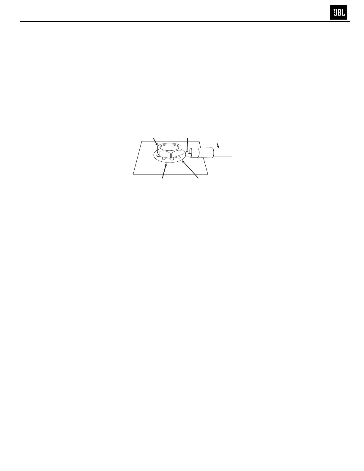
•GND: Connect to the vehicle’s chassis. Refer to
the picture below.
•REM: Connect to the “Remote Out” lead from
the source unit or to a source of switched
12V+ (ACC).
3Aux Output Connectors (RCA)
•Nonfiltered pass-through output. Connect to the
input of an additional amplifier.
4Input Connectors (RCA)
•Connect to the RCA outputs from the source unit
or signal processor.
5Input-Level Control
•Used to match the input level of the amplifier
to the output level of the source unit.
•See Bfor the adjustment procedure.
6Low-Pass Filter Frequency Control
•12dB/octave low-pass filter,
variable from 32Hz to 320Hz.
•See Cfor the adjustment procedure.
7DBO (Dynamic Bass Optimization) Variable
Subsonic High-Pass Filter With Variable Boost (Q)
•For woofers in tuned (vented) enclosures, set
the Frequency control to a value 10Hz below the
enclosure’s resonance (tuned) frequency.
•For woofers in sealed boxes, set the control to
any value you prefer between 30Hz and 50Hz.
•Set the Boost control according to your
preference, being careful not to apply
enough boost to damage your woofer(s).
ADBO High-Pass Filter Frequency control,
variable between 10Hz and 100Hz. See
above for appropriate settings.
BDBO Boost control provides up to
12dB of boost slightly above the high-
pass filter’s frequency. See above for
appropriate settings.
8Remote Level Control (RLC) Connector
•Connect the Remote Level Control (RLC) here,
using the supplied RJ-11 cable.
9Power On LED
•Illuminated when the amplifier is on.
AProtect LED
•Illuminated under any of the following fault
conditions: battery over/under voltage, short
circuit in speaker wires, amplifier is too hot,
amplifier’s output circuit has failed (DC voltage
is present in the amplifier’s output).
BSetting Input Level
ATurn Input Level control counterclockwise to
6V (minimim).
BWith a dynamic music track playing, turn the
head unit’s volume control to the 3/4 position.
CTurn Input Level control clockwise until the
bass output is proportionate to the output of
the high-frequency speakers, according to
your preference.
DInput level is now adjusted correctly.
CSetting the Crossover
ACrossover setting for subwoofers.
Note: Acceptable frequency ranges are indicated
in gray.
DRemote Level Control
The Remote Level Control, if installed, will allow
you to adjust the level of bass while seated in the
listening position.
GTO3501 CAR AUDIO SUBWOOFER AMPLIFIER OWNER’S MANUAL
Factory Bolt Ring Connector
Ground Wire
Note: Remove any paint
below ring connector.
Star Washer
4
GTO3501

Amplifier Troubleshooting Guide
1. Status LED on Amplifier not Lit - Head Unit (Source) Turned ON
Verify: A. Remote turn-on wire from source to amplifier has proper voltage
B. Power (B+) connections at amplifier, terminal blocks, and battery are secure
C. Ground (GND) connections at amplifier and vehicle chassis are secure
D. Battery B+ fuse (if used) is OK
E. Amplifier fuse is OK
F. B+ at battery and B+ at amplifier has proper voltage
2. Status LED’s Lit, No Output from Speakers in Normal Operating Condition
Verify: A. RCA cables from amplifier to source are securely connected
B. Volume adjustment on amplifier is correctly adjusted
C. Source is ON and playing
3. Engine Noise From Speaker(s)
Turn source OFF, Disconnect RCA cables at amplifier. If noise stops, check equipment & cables leading
to amplifier.
Verify: A. RCA cables are of good quality with no breakage to internal shields
B. RCA cables from source to amplifier are not run alongside any power cables
4. Amplifier Output Distorted Music
Verify: A. Source output music to amplifier is not distorted
B. Source output sensitivity is correctly adjusted
5. Amplifier Shuts Down, Green LED’s are Lit - Amplifier is in Thermal Protection Mode
Verify: A. Amplifier is mounted with adequate air circulation around heatsinks or vents
B. Amplifier is not mounted under carpet or sealed enclosure
C. Speakers meet correct impedance for application (mono or stereo hookup)
6. Amplifier Does Not Turn ON, and Red LED is Lit Amplifier (and not Connected to a Shorted Speaker)
Verify: A. Speaker crossover (if used) is not defective
5
GTO3501

Front Plate
Standoff
Trans. Clamp
Trans. Clamp
1380-0003-00
RCA CAP (Red)
RCA CAP (Wht)
6
GTO3501
Part Number Part Number

1 2 3 4
A
B
C
D
4321
D
C
B
A
OP
OP
OP
OP
OP OP 11 25 320 11 320
20HZ~100HZ
AMP
SPEAKER
BALANCED
INPUT
UNIT
BALANCED
INPUT
UNIT
GAIN CONTROL
BASS BOOST
VARIABLE
0dB--12dB/20HZ~100HZ
MODEL FREQ
VARIABLE LP
11HZ--320HZ/12dB MAIN AMP
FRONTL 2ohm/4ohm
AUX OUT L
AUX OUT R +
-
Battery +VCC
-VCC
+V
-V
POWER SUPPLY
7
GTO3501

GTO3501 Electrical Parts List
Part Number Qty Reference Designator
MAIN PCB
Resistors
0702-34R7-02 Resistor 1/2W 4.7Ω±5% 3 R242 R37 R36
0702-4220-02 Resistor 1W 22Ω±5% 3 R142 R141 R140
0702-3101-02 Resistor 1/2W 100Ω±5% 2 R223 R222
0702-24R7-02 Resistor 1/4W 4.7Ω±5% 6 R231 R229 R228 R227 R226 R225
0702-2472-02 Resistor 1/4W 4.7KΩ±5% 1 R122
0702-3271-02 Resistor 1/2W 270Ω±5% 2 R221 R220
07301220XK01 Resistor 1/8W 22Ω±1% 5 R213 R212 R211 R210 R112
0702-1680-02 Resistor 1/8W 68Ω±5% 2 R203 R202
0702-1101-02 Resistor 1/8W 100Ω±5% 7 R42 R138 R137 R136 R134 R133 R132
0702-1201-02 Resistor 1/8W 200Ω±5% 1 R45
0702-1221-02 Resistor 1/8W 220Ω±5% 3 R207 R131 R129
0702-1471-02 Resistor 1/8W 470Ω±5% 1 R240
0702-1821-02 Resistor 1/8W 820Ω±5% 1 R38
0702-1102-02 Resistor 1/8W 1KΩ±5% 8 R201 R200 R113 R33 R32 R31 R30 R25
0702-1431-02 Resistor 1/8W 430Ω±5% 1 R49
0702-1152-02 Resistor 1/8W 1.5KΩ±5% 6 R253 R252 R250 R249 R241 R238
0702-1182-02 Resistor 1/8W 1.8KΩ±5% 2 R48 R41
0702-1302-02 Resistor 1/8W 3KΩ±5% 1 R159
0702-1222-02 Resistor 1/8W 2.2KΩ±5% 2 R204 R217
0702-1332-02 Resistor 1/8W 3.3KΩ±5% 1 R120
0702-1472-02 Resistor 1/8W 4.7KΩ±5% 4 R205 R110 R109 R26
0702-1512-02 Resistor 1/8W 5.1KΩ±5% 1 R39
0702-1562-02 Resistor 1/8W 5.6KΩ±5% 2 R15 R9
0702-1682-02 Resistor 1/8W 6.8KΩ±5% 3 R216 R215 R214
0702-1752-02 Resistor 1/8W 7.5KΩ±5% 1 R50
0702-1103-02 Resistor 1/8W 10KΩ±5% 9 R121 R103 R102 R101 R100 R62 R27 R21
R117
0702-1153-02 Resistor 1/8W 15KΩ±5% 2 R256 R239
0702-1203-02 Resistor 1/8W 20KΩ±5% 3 R119 R18 R17
0702-1223-02 Resistor 1/8W 22KΩ±5% 4 R208 R106 R7 R1
0702-1243-02 Resistor 1/8W 24KΩ±5% 2 R209 R40
0702-1333-02 Resistor 1/8W 33KΩ±5% 1 R118
0702-1473-02 Resistor 1/8W 47KΩ±5% 13 R29 R28 R24 R23 R13 R12 R11 R10 R8 R6
R5 R4 R3
0702-1563-02 Resistor 1/8W 56KΩ±5% 3 R150 R235 R14
0702-1474-02 Resistor 1/8W 470KΩ±5% 1 R206
0702-1104-02 Resistor 1/8W 100KΩ±5% 4 R2 R54 R53 R218
0705-515X-07 Resistor 5W 0.15Ω±5% 6 R260 R259 R237 R234 R233 R236
0704-6202-02 Resistor 2W 2KΩ±5% 2 R108A R107A
0702-1205-02 Resistor 1/8W 2MΩ±5% 1 R44
1204-5011-01 potentiometer B500 KQ L=15 ±15% BOOST 1 VR4
1204-5031-30 potentiometer B50K ±15% R0971G INPUT LEVEL 1 VR1
1204-2041-03 potentiometer A2K/A200K KQ A2K,A200K HP FREQ 1 VR3
1204-5031-34 potentiometer C50K KQ L=15 ±15% LP FREQ 1 VR2
Capacitors
06D212256301 CAP,Electro 2.2UF/50V ±20% 5*11 105C 1 C208
06D211073116 CAP,Electro 100UF/16V±20% 5*11 105C black 3 C104 C138 C137
06D211074100 CAP,Electro 100uF/25V ±20% 6.3*11 105C black 1 C148
06D212264103 CAP,Electro 220uF/25V ±20% 8*12 105C black 2 C209 C139
06D212264102 CAP,Electro 22uF/25V ±20% 5*11 105C black 1 C103 C8
06D214775117 CAP,Electro 470uF/35V ±20% 10*17 105C 2 C134 C133
06D214765000 CAP,Electro 47UF/35V ±20% 5*11 105C 2 C36 C35
06D214763109 CAP,Electro 47uF/16V ±20% 5*11 105C black 1 C102
06D212285101 CAP,Electro 2200UF/35V Φ16*26MM ±20% 105C 2 C124 C122
06D213389001 CAP,Electro 3300UF/63V ±20% 30*25 105C 2 C145 C144
Description
GTO3501
8

Part Number Qty Reference Designator
Description
MAIN PCB
06D212266010 CAP,Electro 22uF/50V ±20% 5*11 105C 8 C4 C5 C7 C9 C10 C13 C14 C204
06D212274001 CAP,Electro 220UF/25V ±20% 8*16 105C 3 C1 C2 C207
06D341849400 MET Capacitor 184/63V ±5% 1 C3
06D346849400 MET Capacitor 684/63V ±5% 1 C47
06D324737200 Capacitor 473/100V ±5% green 1 C24
06D321047200 Capacitor 104/100V ±5% green 3 C46 C211 C206
06D232207000 porcelin cap 22pF/100V ±20% green 2 C44 C42
06D235607000 Capacitor 56PF/100V ±20% 2 C202 C201
06D232217000 porcelin cap 220pF/100V ±20% 1 C38
06D231017000 porcelin cap 100pF/100V ±20% 9 C21 C20 C19 C18 C16 C15 C23 C48 C49
06D234717001 porcelin cap 470PF/100V ±20% 1 C37
06D234737001 Capacitor 473/100V ±20% 1 C205
06D236817000 porcelin cap 680pF/100V ±20% 2 C203 C200
06D231047000 porcelin cap 0.1uF/100V ±20% 18
C101 C121 C120 C118 C117 C115 C114
C100 C32 C30 C1B C1A C129 C128 C130
C131 C146 C147
06D321027200 Capacitor 102/100V ±5% green 1 C142
06D321037200 Capacitor 103/100V ±5% 2 C127 C126
Semiconductors
04PT-4148-04 diode 1N4148 GSS 200MA 75V DO-35 7 D100 D202 D208 D205 D204 D201 D200
04ZL-4004-03 diode 1N4004 DO-41 1 D111
04GS-C6A4-00 diode MIC6A4 1 D106
04WY-82AV104 diode schottky 8.2V DO-35 0.5W 1 DZ100
04GS-R104-00 diode FR104 1A 400V 4 D107 D108 D109 D110
03P1-B817-13 Transistor KTB817 PNP TO-3P 3 Q215,Q220,Q222
03N1-5551-01 Transistor 2N5551 NPN TO-92 4 Q212 Q211 Q210 Q1
03P1-5401-01 Transistor 2N5401 PNP TO-92 2 Q215 Q214
03P1-1015-01 Transistor 2SA1015 150MA 60V 400MW PNP TO-92 2 Q108 Q107
03P1-B649-07 Transistor 2SB649A 1.5A 180V 20W PNP TO-126 2 Q217 Q218
03N1-669A-07 Transistor 2SD669A NPN TO-126 3 Q213 Q201 Q202
03P1-B647-01 Transistor 2SB647 1A 120V 0.9W PNP TO-92 1 Q200
03N1-1815-01 Transistor 2SC1815GR 150MA 60V 400MW NPN TO-92 6 Q122 Q209 Q208 Q102 Q101 Q100
03N1-1047-13 Transistor KTD1047 NPN TO-3P 3 Q204-Q206
01FA-7815-04 +15v Regulator KA7815E TO-220 FAIRCHILD 1 U100
01FA-7915-04 neg15v Regulator KA7915 TO-220 FAIRCHILD 1 U101
03N1-667A-01 Transistor 2SD667AC 1A 120V 0.9W NPN TO-92 1 Q216
03N1-8050-01 Transistor 8050D NPN TO-92 1 Q207
03T1-Z48N-02 MOS Transistor IRFZ48N TO-220 6 Q113 Q114 Q115 Q116 Q117 Q118
2004-0014-00 LED Φ3.0MM blue with blue light 1 LED100
2000-0017-00 LED red with red light Φ3MM 2P 1 LED101
01JR-4560-01 Dual Op-amp NJM4560D -8 4 U1 U2 U3 U4
2601-0202-00 OptoTransistor LCR-0202 1 R43
2202-1602-05 Rectifier UF1602CT AKA 16/200V TO-220 1 D114
2202-1620-05 Rectifier MUR1620CTA KAD 16A/200V TO-220 1 D115
Miscellaneous
1005-5R04-10 toroidal inductor 5UH φ23 φ1.0*5 1 L1A
1380-0003-00 temp switch 90C KSD-301 1
1601-303G-00 fuse 30A/32V DC 2 F100
1404-0020-04 socket AV4-8.4-38 1 RCA1
1501-0209-00 socket Pitch 2.54MM 2PIN 2 CN104 CN105
1413-0001-00 phone socket 6P4C RJ11 HPCB-3021-6P4C black 1 JK1
1501-0300-02 terminal BTS3-24 1
1501-0400-01 terminal BTS4-23 1
3000-GT00-01 transformer Φ40 4:15:8 F1=F2=Φ0.8*12*4TS
S1=S2=Φ0.8*6*15TS S3=S4=Φ0.8*1*8TS 1 L102
1401-0008-00 fuse holder 2PIN BXS2-09 1
GTO3501
9

Part Number Qty Reference Designator
Description
MAIN PCB
PL-L0002-000 sheet ground GND-3 1
2100-0083-02 wire 2PIN P=2.54MM 1007# 26AWG L=85MM
(A2501TOP-2)5MM 105C 1 tem switch
PWM PCB
Resistors
0701-2221-03 SMD Resistor SMD 220Ω1/8W ±1% 0805 1 R17
0701-2101-03 SMD Resistor SMD 100Ω1/8W ±1% 0805 1 R10
0701-2102-03 SMD Resistor SMD 1KΩ1/8W ±1% 0805 6 R31 R30 R29 R28 R26 R15
0701-2302-03 SMD Resistor SMD 3KΩ1/8W ±1% 0805 1 R13
0701-2472-03 SMD Resistor SMD 4.7KΩ1/8W ±1% 0805 1 R11
0701-2682-03 SMD Resistor SMD 6.8KΩ1/8W ±1% 0805 2 R5 R51
0701-2562-03 SMD Resistor SMD 5.6KΩ1/8W ±1% 0805 1 R14
0701-2103-03 SMD Resistor SMD 10K 1/8W ±1% 0805 2 R1 R23
0701-2113-03 SMD Resistor SMD 11KΩ1/8W ±1% 0805 1 R27
0701-2123-03 SMD Resistor SMD 12KΩ1/8W ±1% 0805 1 R24
0701-2153-03 SMD Resistor SMD 15KΩ1/8W ±1% 0805 1 R53
0701-2183-03 SMD Resistor SMD 18KΩ1/8W ±1% 0805 1 R7
0701-2223-03 SMD Resistor SMD 22KΩ1/8W ±1% 0805 2 R18 R9
0701-2333-03 SMD Resistor SMD 33KΩ1/8W ±1% 0805 1 R65
0701-2334-03 SMD Resistor SMD 330KΩ1/8W ±1% 0805 1 R3
0701-2104-03 SMD Resistor SMD 100KΩ1/8W ±1% 0805 3 R25 R12 R4
Capacitors
06D211054104 CAP,Electro 1uF/25V ±20% 4*7 105C 1 C3
06D211074101 CAP,Electro 100UF/25V 6.3*7mm 5mm ±20% 105C 1 C27
06D212273001 CAP,Electro 220UF/16V ±20% 8*7 105C 5MM 1 C22
06D214764103 CAP,Electro 47UF/25V ±20% 6*7 105C 5mm 2 C1 C20
06S321026000 SMD Capacitor SMD 1000pF/50V 0805 NPO ±5% 1 C26
06S121046000 SMD Capacitor SMD 0.1uF/50V 0805 X7R ±10% 2 C4 C25
Semiconductors
04WY-39AV101 diode schottky SMD 3.9V DO-213AA 0.5W 1 ZD2
04WY-15BV-01 diode schottky SMD 15V 1/2W ±2% DO-213AA 1 ZD1
04PT-4148-01 diode SMD 1N4148 DO-213AA 6 D4 D1 D20 D3 D2 D13
03P1-1015-04 Transistor SMD 2SA1015 SOT-23 PNP 1 Q10
03P1-B649-07 Transistor 2SB649A 1.5A 180V 20W PNP TO-126 1 Q6
03N1-1815-04 Transistor SMD 2SC1815 SOT-23 NPN 4 Q3 Q2 Q7 Q1
01TI-L494-09 IC PWM SMD TL494C SO-16 1 U1
03P1-1015-01 Transistor 2SA1015 150MA 60V 400MW PNP TO-92 2 Q9 Q8
Miscellaneous
1501-0409-02 socket PITCH 2.54mm 4PIN 90° 2 CN2 CN1
LED PCB
0701-3102-02 Resistor SMD 1KΩ1/4W ±5% 1206 8 R1 R2 R3 R4 R5 R6 R7 R8
2100-0067-02 wire 2PIN UL1007 AWG26 L=70mm 105 2
2100-0068-02 wire 2PIN UL1007 AWG26 L=210mm 105 1
2005-0009-00 LED LED 2*3*4mm 8 LED1 LED2 LED3 LED4 LED5 LED6 LED7
LED8
06S121046000 SMD Capacitor SMD 0.1uF/50V 0805 X7R ±10% 1 C1
GTO3501
10

11
GTO3501

12
GTO3501

GTO3501
13

1 2 3 4
A
B
C
D
4321
D
C
B
A
+
1
-
2
FED
3
DT
4
C
5
R
6
GND
7
OP1
8
+16
-15
REF 14
CON 13
VCC 12
OP2 11
E2 10
E1 9
TL494CN U1 TL494
R27
11K
R9
22K
C26
102/M C27
100/25V
Q10
A1015
R53
15K
C3
1U/50V
PRO R30
1K
R31
1K
R28
1K
R29
1K
Q3
C1815
R17
220R
C25
104
Q2
C1815
R10
100
R11
4.7K
R13
3K
C2
10/25V
Q6
B649
C1
47/25V
R1
10K
R26
1K
R4
100K
R24
12K
R23
10K
R12
100K
C22
220/16V
R18
22K
R5
6K8
R3
330K
R51
6K8
Q7
C1815
R15
1K
+12
Q1
C1815
R7
18K
DW GNO:
PART NO:
PART NAME:
PRODUCT MODE:
SCALE: 1:1
UNIT: MM
SIZE: A4
REV: MV
DRAWN BY:
CHECKED BY:
APPROVED BY:
DATA:
DATA:
DATA:
POWER
JBL GTO-3501
R65
33K
JUNPING.LI 2007.07.19
C20
47/16V
D1
4148
D13
4148
D2
4148
D3
4148
D4
4148
ZD1
15V
ZD2
3V9
+12V
+12
D20
4148
R25
100k
R14
7K5
1
2
3
4
CN1
CON4
1
2
3
4
CN2
CON4
PRO
REM
DC12V
12V
GND
E2
E1
PRO LED
PRO
Q9
A1015
Q8
A1015
C4
104
DESCRIPTON DATAAPPROVEDDESCRIPTONREV REVPlace Place
DATA
GTO3501
14

12345678
A
B
C
D
87654321
D
C
B
A
DW GNO:
PART NO:
PART NAME:
PRODUCT MODE:
SCALE: 1:1
UNIT: MM
SIZE: A4
REV: MV
DRAWN BY:
CHECKED BY:
APPROVED BY:
DATA:
DATA:
DATA:
POWER
JBL GTO3501
JUNPING.LI 2007.07.19
C100
CC104
C115
CC104
C114
CC104
C102
47u/16V
C142
CL102 R142
22R/ 1/2W
C144
3300U/63V
C145
3300U/63V
D106
6A10
1
1
2
2
3
3CN100
POWER
R129
220R
R131
220R
C101
104
C123
2200U/35V
PGND
REM
+12V
C124
2200U/35V
C104
100U/16V
DZ100
8V2
D114
MUR1620CT
D115
MUR1620CTR
Q115
IRF48N
Q116
IRF48N
R133
100R
R137
100R
D110
FR204
D109
FR204
C122
2200U/35V
Q117
IRF48N
Q118
IRF48N
R134
100R
R138
100R
C126
CL103
R140
22R/ 1/2W
C127
CL103
R141
22R/ 1/2W
Q100
C1815
R106
22K
R101
10K
R100
10K
Q102
C1815
R102
10K
R103
10K
R109
4.7K
Q101
C1815
R113
1K
R110
4.7K
R112
22R
R119
20K
R118
33K
R120
3.3K
Q107
A1015
Q108
A1015
-V
MUTE
D108
FR204
D107
FR204
+V1
C117
CC104
C137
100U/16V
C118
CC104
C138
100U/16V
-V1
C130
CL104
C131
CL104
D100
1N4148
C103
22U/25V
R117
10K
C121
CC104
C120
CC104
C146
CL104
C147
CL104
C133
470U/35V
C134
470U/35V
Vin
1
GND
2
Vout 3
U100 L7815
Vout 3
GND 2
Vin
1
U101 L7915
F40
F1=F2=F0.8*12 4TS
S3=S4=F0.8*1 8TS
+VCC
-VCC
2
211
F100A 20A
4
433
F100B 20A
-V
R132
100R
R136
100R
Q113
IRF48N
Q114
IRF48N
C1A
CC104
C1B
CC104
R107A
2K/2W
R108A
2K/2W
S1=S2=F0.8*8 15TS
C128
CC104
C129
CC104
1 2
L1A
5UH
2
4
9
8
6
1
3
7
10
5
8
L102
TRANC-2
11
33
22
4
CN103
CON4P-1 LED101
RED
PRO
1
2
CN105
80C
PRO
11
33
22
4
CN102
1
2
CN104
R121
10K
+15V
R122
4K7/0.25W
LED100
BLU
D111
1N4004 C105
220U/25V
DESCRIPTON DATAAPPROVED
DESCRIPTONREV REV
Place Place
DATA
1
2
CN4
CON2.54*2
RT1
90℃
1
2
CN5
CON2.54*2
R11
1K
R10
1K
R9
1K
R8
1K
R7
1K
R6
1K
R5
1K
R4
1K
LED8
LED
LED7
LED
LED6
LED
LED5
LED
LED4
LED
LED3
LED
LED2
LED
LED1
LED
GTO3501
15

12345678
A
B
C
D
87654321
D
C
B
A
Q200
B647
Q214
5401
R202
68R
Q207
S8050
Q211
5551 Q212
5551
Q213
D669
Q201
D669 Q202
D669
Q219
B817
R206
470K
LIN
R207
220R
R204
2K2
R205
4.7K
C204
W22U/50V
R242
4.7R/0.5W
C211
CL104
C205
CC473
R214
6.8K
R211
22R
R208
22K
R210
22R
C201
CC56P/100V
R217
2.2K
R218
100K
C206
CL104
R200
1K
R220
270R/0.5W
C200
CC681/100V
R222
100R/0.5W
Q204
D1047
R225
4.7R0.25W
Q205
D1047
R226
4.7R0.25W
-V1
Q217
B649
R203
68R
Q216
D667
R216
6.8K
R213
22R
R212
22R
C202
CC56P/100V
R201
1K
R221
270R/0.5W
C203
CC681/100V
R228
4.7R0.25W
R223
100R/0.5W
R229
4.7R0.25W
+V1
Q215
5401
Q218
B649 Q220
B817
D201
4148
D200
4148
R240
470R
C209
220U/25V
R209
24K
MUTE
R235
56K
C208
2.2U/50V
R215
6.8K
C207
NP220U/26V Q209
C1815
Q210
5551
R239
15K
D208
4148
D204
4148
D202
4148
Q208
C1815
PRO
+VCC
-VCC
R249
1K5 R250
1K5
R252
1K5 R253
1K5 R256
15K
D205
4148
R234
0.15R/5W
R233
0.15R/5W
R259
0.15R/5W R260
0.15R/5W
DW GNO:
PART NO:
PART NAME:
PRODUCT MODE:
SCALE: 1:1
UNIT: MM
SIZE: A4
REV: MV
DRAWN BY:
CHECKED BY:
APPROVED BY:
DATA:
DATA:
DATA:
AMP
JBL GTO3501
JUNPING.LI 2007.07.19
1
2
3
4
CN200
Q206
D1047
R227
4.7R0.25W
R238
1K5
R236
0.15R/5W
R231
4.7R0.25W
Q222
B817
R241
1K5
R237
0.15R/5W
R150
56K
Q122
C1815
C148
100U/25V R159
3K
DESCRIPTON DATAAPPROVED
DESCRIPTONREV REV
Place Place
DATA
GTO3501
16

123456
A
B
C
D
654321
D
C
B
A
DWGNO:
PARTNO:
PARTNAME:
PRODUCTMODE:
SCALE: 1:1
UNIT: MM
SIZE: A4
REV: MV
DRAWNBY:
CHECKEDBY:
APPROVEDBY:
DATA:
DATA:
DATA:
INPUT
JBL GTO3501
JUNPING.LI 2007.07.19
R5 47K
R1
22K
C1
NP/220U/25V
C19 CC101
R6
47K
R3
47K
INPUT 1
2
CH1-INPUT
C4
W22U/50V
C15
CC101
C18
CC101
C5
W22U/50V R4
47K
R12 47K
R7
22K
C2
NP/220U/25V
C20 CC101
R11
47K
R8
47K
INPUT 5
6
CH2-INPUT
C7
W22U/50V
C16
CC101
C21
CC101
C9
W22U/50V R10
47K
R2947K
R2447K
R23 47K
R28 47K
C44 CC22P
C42 CC22P
R32
1K
R33
1K
C13
W22U/50V
C14
W22U/50V
3
4
CH1-OUT
R54
100K
R53
100K
+15V
-15V
-15V
+15V
7
8
CH2-OUT
3
21
U1A
NJR4560
5
67
8 4
U1B
NJR4560
3
2
1
U3A
NJR4560
5
6
7
8 4
U3B
NJR4560
-15V
3
21
U2A
NJR4560
C23 CC101
C10
W22U/50V
R30
1K
C30
CC104
C32
CC104
C35
47U
C36
47U
R37
4R7
R36
4R7
+V1
-V1
R17
20K
R18
20K
4 6
5VR1B
B50K
R38
820R R13
47K C37
CC471
3
21
U4A
NJR4560
R31
1K
R39 5K1
C38 CC221
R OUT
L OUT
L OUT
R OUT C46
104/MET
C47
684/MET
5
67
84
U2B
NJR4560
+15V
-15V
R27
10K C24
473/MET
R50
7K5
+15V
R62 10K
REM
R25
1K
R40
24K
+15V
R21
10K Q1
5551
R41
1K8
+15V
R44
2M
R42
100
1
1
3
3
2
2
4
JK1
RJ-11
R45 200
R26 4K7
+15V
REM
13
2
VR2A
C50K
R9
5K6
4 6
5
VR2B
C50K
5
67
84
U4B
NJR4560
+15V
-15V
C3
184/MET
13
2
VR3A
A2K
R14
56K
46
5VR3B
A200K
R49
430R
1 3
2VR4A
B500
R48
1K8
R2
100K
C8
22U/16V LIN
R15
5K6
R43
LC202
C48
CC101
C49
CC101
DESCRIPTON DATAAPPROVED
DESCRIPTONREV REV
Place Place
DATA
PV MV CC101P +-5% C48 C49 07-07-19
ADD
GTO3501
17
Other manuals for Grand Touring Series GTO3501
3
Table of contents
Other JBL Amplifier manuals

JBL
JBL GT-X646 User manual

JBL
JBL Grand Touring Series GTO1004 User manual

JBL
JBL AVR580 User manual

JBL
JBL CSA-2120 User manual

JBL
JBL 6007 Manual

JBL
JBL GTO24001 User manual

JBL
JBL MA6004 User manual

JBL
JBL CS200.1 User manual

JBL
JBL SIMPLY CINEMA ESC200 User manual

JBL
JBL Grand Touring Series GTO3501 User manual