INSTALLATION
2
THANK YOU
for purchasing a JBL CS Series amplifier.
In order that we may better serve you
should you require warranty service for
your new amplifier, please retain your
original purchase receipt and register your
new JBL amplifier online at www.jbl.com.
WARNING
Playing loud music in an automobile
can hinder your ability to hear traffic and
permanently damage your hearing. We
recommend listening at low or moderate
levels while driving your car. JBL accepts
no liability for hearing loss, bodily injury or
property damage resulting from the use or
misuse of this product.
IMPORTANT
To get the best performance from your
JBL CS Series amplifiers, we strongly
recommend that installation be entrusted
to a qualified professional. Although
these instructions explain how to install
CS amplifiers in a general sense, they do
not show specific installation methods
that may be required for your particular
vehicle. If you do not have the necessary
tools or experience, do not attempt the
installation yourself. Instead, please ask
your authorized JBL car audio dealer
about professional installation.
INSTALLATION
WARNINGS AND TIPS
• Always wear protective eyewear when
using tools.
• Turn off the audio system and other
electrical devices before you start.
Disconnect the (–) negative lead from
your vehicle’s battery.
• At the installation sites, locate and
make a note of all fuel lines, hydraulic
brake lines, vacuum lines and electrical
wiring. Use extreme caution when cut-
ting or drilling in and around these areas.
• Check clearances on both sides of
a planned mounting surface before
drilling any holes or installing any
screws. Remember that the screws
can extend behind the surface.
• Before drilling or cutting holes, use a
utility knife to remove unwanted fabric
or vinyl to keep material from snagging
in a drill bit.
• When routing cables, keep input-signal
cables away from power cables and
speaker wires.
• When making connections, make
certain they are secure and properly
insulated.
•If the amplifier’s fuse must be replaced,
use only the same type and rating as
that of the original. Do not substitute
another kind.
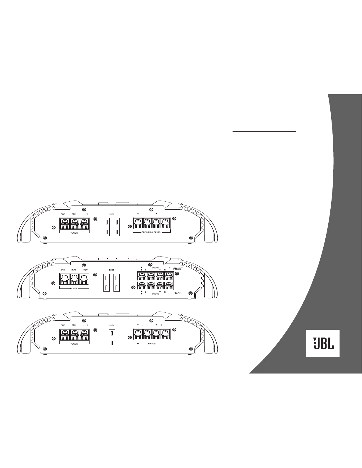
CHOOSING A LOCATION
AND MOUNTING THE
AMPLIFIER
Choose a mounting location in the trunk
or cargo area where the amplifier will not
be damaged by shifting cargo. Amplifier
cooling is essential for proper amplifier
operation. If the amplifier is to be installed
in an enclosed space, make sure there is
sufficient air circulation for the amplifier
to cool itself.
When mounting the amplifier under a
seat, ensure that it is clear of all moving
seat parts and does not affect the seat
adjustments. Mount the amplifier so it
is not damaged by the feet of backseat
passengers. Make sure that the amplifier
is mounted securely using nuts and bolts
or the supplied mounting screws.
Mount the amplifier so that it remains
dry – never mount an amplifier outside
the vehicle or in the engine compartment.