JBL GTH400 User manual

GTH400-20107 06/03/98 15:49 Side 26

GTH400
GTH400
6/5/4/3CHANNELAUTOMOTIVEPOWERAMPLIFIER
OWNER’SMANUAL
GTH400-20107 06/03/98 15:49 Side 1

Table of Contents
1. Introduction...................................................................................... 3
1.1 Features.................................................................................... 4
1.2 About Installation...................................................................... 4
2. Installation and use.......................................................................... 5
3. System Design with the GTH400..................................................... 6
3.1 Speaker Requirements ............................................................. 6
3.2 Typical Applications.................................................................. 7
4. Installation and Use ......................................................................... 9
4.1 Controls and Connectors.......................................................... 9
4.2 Internal Adjustments................................................................ 12
Speaker-Level Input Impedance Adjustments......................... 12
Crossover Frequency Adjustments.......................................... 12
Custom Chip construction....................................................... 13
Remote Chassis Installation .................................................... 13
Unter-Dash Remote Installation............................................... 14
In-Dash remote Installation...................................................... 14
Power Supply Connections ..................................................... 14
Simultaneous Speaker Stereo-Mono Connection Diagram..... 16
Speaker-Level Input Harness - Color Codes........................... 17
5. Adjusting the Gain .......................................................................... 17
6. Important Characteristics ............................................................... 19
7. In Case of Difficulty......................................................................... 21
8. Specifications ................................................................................. 23
Owner’s Warranty Information
Model Number
Serial Number
Dealer Name
City, State, Zip
Sales Receipt Number
Date of Purchase
GTH400-20107 06/03/98 15:49 Side 2

3
1. Introduction
Thanks for purchasing your new GT
series automotive multichannel ampli-
fier. Your GT series amplifier will easily
connect to virtually any car audio
system, whether it is factory installed or
one purchased separately. The GTH400
includes an abundance of unique
features which are described in this
manual. The most obvious feature of
the GTH400 is its 6-channel,
staggered-power design. This design
provides the simplicity of driving an
entire system with a single amplifier
without compromise. The flexible
design of the GTH400’s built-in
crossover circuitry also allows elaborate
systems to be built more simply than
with conventional components. For
optimum performance, the power
amplifier circuitry is a fully discrete
design notable for its low distortion and
unusually clean and clear sound quality.
In addition to conventional preamp-
level inputs, the GTH400 features JBL’s
Universal Interface design, which
facilitates simple connection to factory
radios with the low distortion that is
usually only associated with preamp
level connection. In addition, when
using a high-powered (BTL) radio
through the speaker-level inputs,
Common Sense turn-on circuitry
senses the common-mode voltage
present on the radio’s speaker wires,
turning the amplifier on without an
additional remote wire.
GTH400-20107 06/03/98 15:49 Side 3

4
1.1 Features
Theory of Operation –
Virtual Center Image Enhancer
JBL’s breakthrough “Virtual Center”
circuitry is the result of the
understanding of how the human ear
responds to timing, frequency, and
amplitude cues to determine the
apparent direction of a sound source.
Virtual Center circuitry manipulates the
analog signal in real time to provide
each of the driver’s ears with the signal
they would receive if the driver was
seated in the center of the vehicle. This
provides a stable, centered image to
the driver much like that obtained with
a dedicated center-channel
loudspeaker.
To restore the spaciousness that is
generally lost in the small confines of a
car interior, the rear channels utilize
differential-mode ambience recovery to
restore the ambience information pres-
ent in all conventional stereo
recordings. Unlike DSP, the JBL
circuitry does not add synthetic reverb,
but recovers real information that is
masked in conventional systems. As a
result, the overall effect from the Virtual
Center circuitry of the GTH400 is
incredibly realistic, yet simple to adjust
and use. Best of all, the “Virtual Center”
and ambiance recovery circuits do not
require specially encoded recordings
and work with virtually all conventional
stereo tapes, discs, and broadcasts.
1.2 About Installation
Although the GTH400 is designed to
make installation as easy as possible, it
is an extremely sophisticated product
that requires proper installation and
setup to realize its full performance
potential. If you feel you do not have
the necessary knowledge and skills, we
strongly recommend that the
installation be done by your
authorized JBL dealer.
If you choose to install the GTH400
yourself, read all of the information in
this manual before you start the
installation. Pay particular attention to
the safety precautions and notes.
GTH400-20107 06/03/98 15:49 Side 4

5
2. Installation and use
Refer to the “Crossover Frequency
Adjustments” and “Speaker-Level Input
Impedance Adjustments” sections of
this manual to see if you will need to
make alterations to their factory
settings.
1. Disconnect the negative cable from
the battery. Note: If the vehicle’s
radio features a code type security
system, make certain you know
the code before disconnecting the
battery!
2. Run a minimum AWG #8 power
cable complete with a 60 amp fuse
(not included) directly from the
positive +12V battery terminal to
the desired amplifier location. Keep
the fuse within 6" of the battery
terminal, and position it before the
wire runs through any metal
partition.
3. Note: All wiring connections should
be made either by soldering with
heatshrink tubing insulation or with
high quality crimp-type insulated
connectors installed with a
professional-type, articulated
crimping tool. Soldering crimp-type
terminals is recommended for
additional
security. Never use wire nuts,
insulation-displacement connectors
(i.e. ScotchLok type), or twist and
tape connections. Do not use
electrical tape; it will loosen with
age and extreme temperatures.
4. Mount amplifier in the desired
location using the included screws.
5. Connect power wiring as shown in
the Wiring Diagram on page 18.
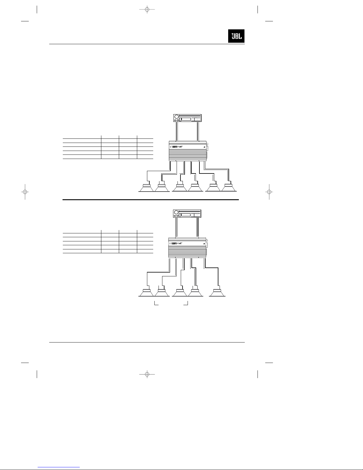
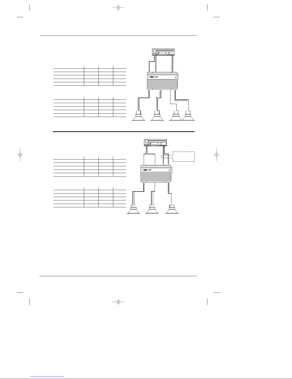
6. Connect the outputs from the head
unit to the appropriate inputs of the
amplifier according to the Wiring
Diagram (page 18) with either (or
both) high quality low-level signal
cables with RCA plugs, or the
supplied speaker-level input
connector.
7. Install the remote control in the
desired location. Connect and run
the cable from the remote to the
amplifier.
8. Connect the speakers to the ampli-
fier according to the Wiring Diagram
on page 18.
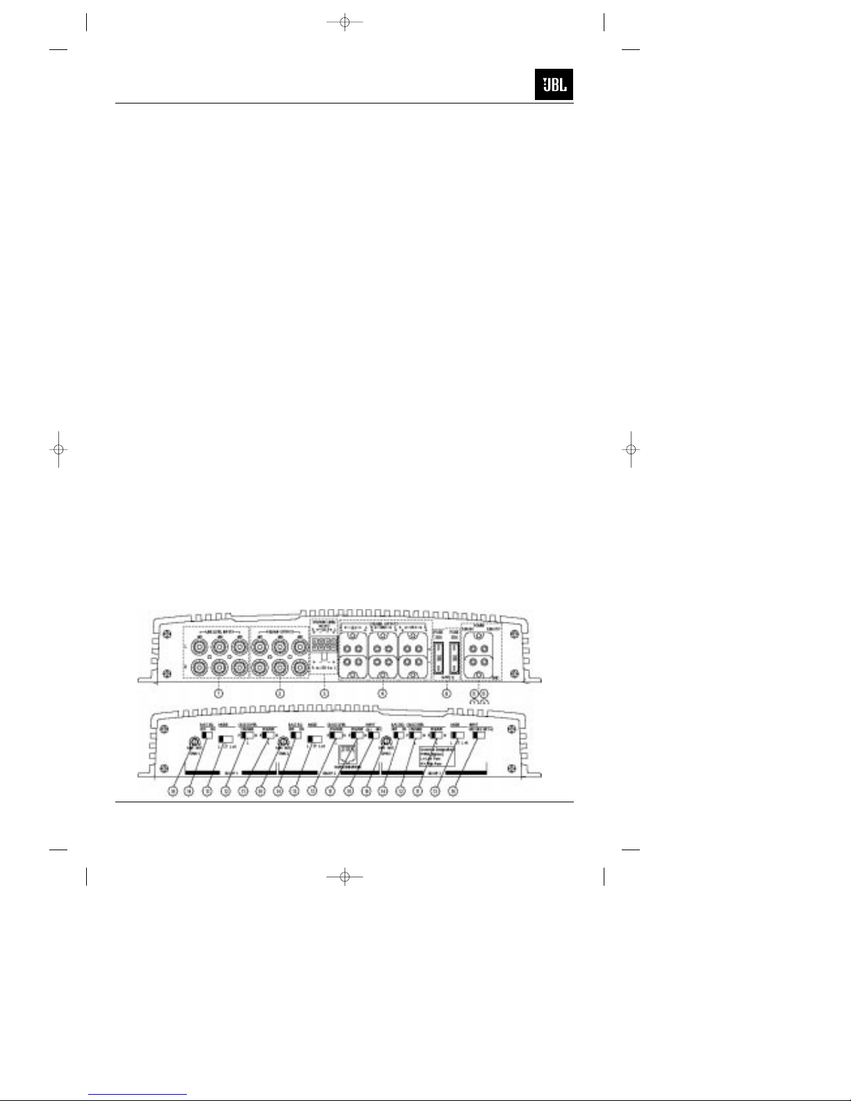
9. Turn the gain controls to the
1/4-position for all groups.
10. Set the bass boost of each group to
the desired position.
11. Set the crossover switches for each
group as desired.
12. Set the Group 2 Input and Group 3
Input as desired.
13. Set the mode switches to Stereo,
Left + Right, or Left Input Only
operation for each group.
14. Double-check your switch settings.
Reconnect the negative battery
cable. Note: Incorrect switch
settings can damage your speakers!
15. Turn on the signal source at a low
volume level, and check for the
correct output from each speaker.
16. Adjust the amplifier gain controls
using the procedure described in
the “Adjusting the Gain” section
(page 25).
17. Read the rest of the manual to get
maximum use and enjoyment from
your amplifier.
GTH400-20107 06/03/98 15:49 Side 5

3. System Design Using
the GTH400
3.1 Speaker Requirements
When used in the non-bridged mode a
group-channel of the GTH400 can
easily drive two 2-ohm speaker loads.
When only one speaker is connected to
the left and right outputs of a group,
virtually any conventional speaker may
be used. When two speakers are
connected in parallel to a single output
(left or right) of a given group, each
speaker must have a minimum
impedance of at least 4 ohms. This
ensures that the combined load will not
drop below 2 ohms. Although the
amplifier will not be damaged, load
impedances lower than 2 ohms will
eventually cause the amplifier to
overheat, activating the protection
circuits and causing the unit to shut off
until it cools down sufficiently.
When a group of the GTH400 is in
bridged mode, the combined
impedance of the speaker (or speakers)
connected to the bridged channels
should be at least 4 ohms. As in the
example above, sustained operation of
the GTH400 in bridged mode with less
than 4 ohms will likely cause
overheating.
The GTH400 must not be used with
speakers that have either one of their
input terminals wired to the frame of
the speaker or to the chassis of the
vehicle.
(+)
(–)
(+)
(–)
Parallel Wiring
Series Wiring
2 ohms
Nominal
Impedance
8 ohms
Nominal
Impedance
4ohms
4ohms
4ohms 4ohms
6
GTH400-20107 06/03/98 15:49 Side 6

7
3.2 Typical Applications
The diagrams on pages 8 & 9 show
the most common basic system
configurations of the GTH400. One
or more of these building blocks may
be combined to form elaborate system
designs.
The GTH400 uses the terminology
“Group 1,” “Group 2” and “Group 3” to
indicate the three main signal paths
within the amplifier. Each “group” may
consist of a mono bridged signal or a
stereo pair of L+R signals depending
on the system configuration.
RL RL
– + – + – + – +
L+
L–
R+
R–L+
L–L+
L–
R+
R–R+
R–
– + – +
Application 1
6-Channel Bi-Amplified System with
Non-Fading Subwoofers
GTH400
GR 1 GR 2
GR 1 GR 2
GR 3
RL RL RL
Front Speakers Rear Speakers Subwoofers
Group 1 Group 2 Group 3
Mode Stereo Stereo Stereo
Group 2 Input – GR 2 –
Group 3 Input – – GR 1+2
Speaker Crossover High Pass High Pass Low Pass
Preamp Crossover – – –
– + – + – +
L+
L–
R+
R–L+
L–L–
R+
R–R+
– + – +
Application 2
5-Channel Bi-Amplified System with
Non-Fading Mono Subwoofer
RL RL
Preamp or
Speaker-Level
Input
Front Rear
RL RL
GR 1 GR 2
GR 1 GR 2
GR 3
RL RL
Preamp or
Speaker-Level
Input
Front Rear
GTH400
Front Speakers
Satellite Speakers
Rear Speakers Subwoofer
Group 1 Group 2 Group 3
Mode Stereo Stereo L+R
Group 2 Input – GR 2 –
Group 3 Input – – GR 1+2
Speaker Crossover High Pass High Pass Low Pass
Preamp Crossover – – –
RL RL
GTH400-20107 06/03/98 15:49 Side 7

8
L L RL
R+
L–
Application 4
3-Channel Bi-Amplified
4-Channel Input (Fading Subwoofer)
L L RR
GR 1 GR 3GR 2
Group 1 Group 2 Group 3
Input Mode L L L+R
Group 2 Input – GR 2 –
Group 3 Input – – GR 3
Speaker Crossover High Pass High Pass Low Pass
Preamp Output Crossover – – –
2-Channel Input (Mono Subwoofer)
Group 1 Group 2 Group 3
Input Mode L L L+R
Group 2 Input – GR 2 –
Group 3 Input – – GR 1+2
Speaker Crossover High Pass High Pass Low Pass
Preamp Crossover – – –
L L RL
– + – + – +
R+
L–R+
L–L+
L–R+
R–
– +
Application 3
4-Channel Full-Range or Bi-Amplified
Preamp or
Speaker-Level
Input
Front Rear
GTH400
GR 1 GR 2
GR 1 GR 2 GR 3
GR 3
GR 1 GR 2 GR 3
Front Speakers
Use these when
4-channel output
is available.
R+
L–R+
L–
GTH400
Main Speakers
Note: Image Enhancement cannot be used in these applications.
Subwoofer
Rear Speakers
or Subwoofer
Group 1 Group 2 Group 3
Input Mode L L Stereo
Group 2 Input – GR 2 –
Group 3 Input – – GR 3
Speaker Crossover Flat Flat Flat
Preamp Output Crossover – – –
4-Channel Bi-Amplified with
Fading Mono Subwoofers
Group 1 Group 2 Group 3
Input Mode L L L+R
Group 2 Input – GR 2 –
Group 3 Input – – GR 3
Speaker Crossover High Pass High Pass Low Pass
Preamp Crossover – – –
RL RL
Front Rear
RL
RL RL
4-Channel Full-Range
*Stereo subwoofers may also be used by selecting “ST”
on the group 3 input mode switch.
Note: Image Enhancement cannot be used in these applications.
GTH400-20107 06/03/98 15:49 Side 8

9
4. Installation and Use
4.1 Controls and Connectors
1. Preamp-Level Input Connector –
Use these connectors for line (pre-
amp) level inputs to the amplifier.
2. Preamp-Level Output Connector –
Use these outputs to send
signal to additional amplifiers.
3. Speaker-Level Input Connector –
Use this connector for speaker level
input signals. A wire harness is
supplied for use with this
connector. See “Audio Input
Connections” section (page 23) for
wiring instructions. This input also
includes JBL’s Common Sense
input circuitry which turns the
amplifier on as soon as the high
powered head unit connected to
this input is turned on.
4. Speaker Output Connectors –
Connect speaker wiring to these
connectors. See wiring directions
for more information.
5., 6., 7., 8. Power Connector –
Connection for power wires. See
wiring directions for information on
proper connections.
9. Fuses – Two 30 Amp ATC type
fuses.
10. Gain Controls – Use these controls
to adjust the gain of the amplifier
channel group. See the “Adjusting
the Gain” section (on page 25) for
tips on proper setup.
11. Preamp Crossover Switches – These
switches control the built-in cross-
overs that are directed to the
preamp-output connectors. Set the
switch to F (flat) for full-band
operation for that group. Set the
switch to L (low) to activate the low-
pass filter on the pre-amp output
group (for subwoofer use or to use
in conjunction with a high-pass
filtered input signal to create a
bandpass crossover for a midrange
or midbass driver). Set the switch to
High-Pass to activate the high-pass
filter for use with satellite speakers
or tweeters on the pre-amp output
group.
12. Speaker Crossover Switches –
These switches control the built-in
crossovers that are connected to
each group's power amplifier cir-
cuitry. Set the switch to F (flat) for
full band operation on a group. Set
this switch to L (low) to activate
the
low-pass filter on the selected
amplifier group for subwoofer use or
GTH400-20107 06/03/98 15:49 Side 9

10
to use in conjunction with a high-
pass filtered input signal to create a
bandpass crossover (for a midrange
or midbass driver). Set the switch to
H (high) to activate the high-pass
filter for use with satellite speakers or
tweeters on an amplifier group.
13. Mode Switches – These switches are
used to set the input mode for both
preamp and speaker-level inputs.
Set the switch to ST(ereo) for normal
operation on the group using
individual left and right inputs. Set
this switch to L to drive both the left
and right outputs with only a single
input on the left jack. Set the switch
to L+R to sum the left and right
inputs for a mono output on the
group. These switches do not affect
the preamp outputs.
14. Bass EQ Switch – These switches
activate a built-in Bass Boost circuit
used to increase low-bass output on
the selected group. These switches
do not effect the preamp outputs.
15. Group 2 Input Switch – This switch is
used to select which inputs will drive
Group 2 of the amplifier. Put the
switch in position “GR 1” to allow
Group 2 to be driven by the Group 1
inputs. Put the switch in the “GR 2”
position to drive Group 2 with the
Group 2 inputs.
16. Group 3 Input Switch – This switch is
used to select which inputs will drive
Group 3 of the amplifier. Put the
switch in position “GR 3” to allow
Group 3 to be driven by the Group 3
inputs. Put the switch in the “GR 2”
position to drive Group 3 with the
Group 2 inputs. Put this switch in the
“GR 1+2” position to drive Group 3
with the sum of Group 1 and 2 for a
non-fading subwoofer output on
Group 3.
17. Remote Bypass/On Indicator – This
indicator is on when the Imaging
Enhancer is engaged and off when
the Imaging Enhancer is bypassed.
18. Driver/All Optimizer Indicator – This
indicator is on when the Virtual Center
Channel circuitry is in “Driver” opti-
mization mode and off when it is in
the “All” passenger mode. Note: The
enhancer on indicator must be on
before driver’s mode can enabled.
19. Front Ambience Control and
On/Bypass Switch – Rotating this
control adjusts the amount of
ambience and front staging width
produced by the Imaging Enhancer.
Pulling the knob places the Imaging
Enhancer in “Bypass” mode.
Pushing in the knob places the
Imaging Enhancer in “On” mode.
20. Rear Ambience and Driver/All
Optimizer Control – Rotating this
knob controls the amount of rear-fill
ambience and the “room size” of the
acoustic environment when used in
a system with rear speakers. Pulling
the knob out places the Imaging
Enhancer in “All” passengers opti-
mization mode. Pushing the knob in
places the unit in “Driver” optimizati-
on mode. Best results at the driver’s
position will be achieved with the
control in the “Driver” setting.
Power Indicator LED (on amp chassis
top) – LED steadily illuminates for normal
operation. LED blinks when protection
circuitry or muting is engaged.
19 20
17 18
MIN MAX
BYPASS
ENHANCER
ON
IMAGING ENHANCER
ENHANCER ON DRIVER MODE
FRONT AMBIENCE REAR AMBIENCE
ALL
DRIVER
MIN MAX
GTH400-20107 06/03/98 15:49 Side 10

11
+
-
+
-
+
-
Buffer
Buffer
Buffer
Buffer
Buffer
Buffer
1
2
31
2
3
1
2
3
1
2
1
2
1
2
3
1
2
3
1
2
3
1
2
3
CH. 1 L IN
CH. 1 R IN
CH. 2 L IN
CH. 2 R IN
CH. 1 L OUT
CH. 1 R OUT
CH. 2 L OUT
CH. 2 R OUT
IMAGE
ENH.
1
2
3
GROUP 3
INPUT
++
1 – GR 3
2 – GR 2
3 – GR 1+2
1
Speaker
Crossover
1 – Flat
2 – Low Pass
3 – High Pass
Preamp
Crossover
1 – Flat
2 – Low Pass
3 – High Pass
GR 3
Input Mode
∑
∑
++
GR 1
GR 2
GR 3
L
L
L
R
R
Buffer
Buffer
Buffer
Buffer
GR 1
GR 2
L
L
R
R
R
LP
HP GR 1 L
PREOUT
X-OVER
GR 1 MODE SWITCH
GR 2 MODE SWITCH
1
2
3
1
2
3
LP
HP GR 1 R
PREOUT
X-OVER
1
3
2
1
2
3
LP
HP GR 2 L
PREOUT
X-OVER
1
3
2
1
2
3
LP
HP GR 2 R
PREOUT
X-OVER
1
3
2
1
2
3
LP
HP GR 3 L
PREOUT
X-OVER
1
3
2
1
2
3
LP
HP GR 3 R
PREOUT
GR 3 Left Speaker Out
GR 3 Right Speaker Out
X-OVER
1
3
2
1
3
2
1
3
2
1
3
2
BASS BOOST
AMP
AMP
GR 2 Left Speaker Out
GR 2 Right Speaker Out
BASS BOOST
AMP
AMP
1
3
2
1
3
2
GR 1 Left Speaker Out
GR 1 Right Speaker Out
BASS BOOST
AMP
AMP
❶
❶
❶
❶
❷
❷
❷
❷
GTH400 Block Diagram
∑
∑
∑
∑
Mode
1 – L
2 – Stereo
3 – L+R
❸
GROUP 2
INPUT
1 – GR 1
2 – GR 2
❸
❸
❸
Buffer
Buffer
Buffer
Buffer
Buffer
Buffer
Speaker-level
inputs
Preamp-level inputs
+
-
Buffer
+
+
+
+
GTH400-20107 06/03/98 15:49 Side 11

12
4.2 Internal Adjustments
Speaker-Level Input
Impedance Adjustments
The speaker level inputs of the GTH400
come factory set with 100k ohm input
impedance. This will provide the lowest
distortion operation from the speaker
outputs of most modern head units by
reducing the power the amplifier in the
head unit must deliver to practically
nothing. On some older, or lower-priced
head units, this load will not facilitate
proper fader operation. To allow for
this, we have provided the ability to
change the input impedance of the
speaker-level inputs to 15 ohms. This is
accomplished by moving the jumpers
shown on the diagram above. This in-
put is also capable of directly accepting
signals, when in the 100k ohm setting,
from many Balanced Line Drivers such
as those sometimes used in competi-
tion vehicles. For best results, a
Balanced Line Driver capable of at least
4V nominal output should be used.
If the head unit has 4 channels of built-
in amplification and/or an electronic
fader control, you should leave the
jumpers in the factory set position.
If the head unit has 2 channels of
amplification, with a speaker-level
fader, the jumpers should be set to the
15-ohm position. This will always be a
rotary-type control, not one controlled
by electronic pushbuttons.
If you are not certain of the type of
fader control your unit has, measure the
resistance across one set of speaker
outputs with an ohmmeter (with the
head-unit off). Adjust the fader control
through its entire adjustment range. If
there is a change in the resistance as
the control is adjusted, set the jumpers
to the 15-ohm position. (See step 1,
page 16 to remove bottom cover.)
Crossover Frequency Adjustments
The GTH400 amplifiers include built-in
frequency selectable crossovers. One
crossover is connected in series with
the amplifier circuitry and the other
crossover is connected to the preamp
level output jacks. These crossovers
can be set in either the F (full bandwidth
operation), L (subwoofer operation), or
H (satellite operation).
The crossover frequencies are set by
chips inside the amplifier. These chips
are simply a set of resistors, connected
across the pins and molded into a
single package. The crossover
frequencies may be changed to any
value desired by changing the resistor
network.
Frequency Resistor JBL Part
Value Number
50Hz 47k Ω1-23-750
80Hz 33k Ω1-23-817
120Hz 22k Ω1-23-820
200Hz 12k Ω1-23-821
250Hz 10k Ω1-23-810
375Hz 6.8k Ω1-23-822
500Hz 4.7k Ω1-23-815
650Hz 3.9k Ω1-23-823
2.5kHz 1k Ω1-23-824
5kHz 470 Ω1-23-816
150HMS 100K 150HMS 100K
SPEAKER
INPUT
IMPEDANCE
SELECTOR
LINE INPUT PREAMP OUT
150HMS 100K 150HMS 100K
JUMPER SELECTOR
SELECT 100K OR 15 OHMS
GTH400-20107 06/03/98 15:49 Side 12

13
Custom Chip Construction
Regardless of whether you build or buy
it, the necessary resistor network has
the following configuration:
•Each resistor in the package has the
same value.
•If you know the crossover frequency
you want, you can calculate the
resistor value necessary by solving the
following equation:
Resistor 2,500,000
Value = Frequency in Hz
in ohms
•Use the following equation if you have
a resistor pack of a known value, and
want to find its crossover frequency:
Frequency 2,500,000
in Hz =Resistor Value
in ohms
•To build chips from discrete resistors,
solder the resistors to a standard 14-
pin “DIP Header” according to the
diagram. If a DIP Header is not
available, you may bend the leads of
1⁄4-watt resistors 90 degrees, trim them
to 1⁄8"-length, and insert them directly
into the chip sockets.
To change the crossover frequency
change the resistor network as follows:
1. Remove the screws from the
bottom panel as shown below.
2. Select which resistor module, high
pass or low pass, that you wish to
change.
3. A chip puller, which can be
obtained from any electronics store,
is recommended to remove the
resistor chip. Pull the resistor chip
from the socket as shown in the
figure below.
4. Place the new module in the socket
making sure all pins are lined up
with the socket holes. Press the
module firmly into the socket.
5. Replace the bottom lid.
For further information on how to use
the speaker output and preamp output
crossovers for system building see the
“Typical Applications” and “Add-On
and Upgrade Steps” sections.
Remote Chassis Installation
The wired remote of the GTH400 can be
installed either in dash or under dash.
HIGH PASS
FILTER
FREQUENCY
SELECTION
MODULE
LOW PASS
FILTER
FREQUENCY
SELECTION
MODULE
C10
C13
JBL INC.
NORTHRIDGE, CA
JBL GTS600
PC00108800
REV A
CROSSOVER
GTH400-20107 06/03/98 15:49 Side 13

14
Under-Dash Remote Installation
1. Set the GTH400 remote in the
installation location and mark two
mounting screw hole locations.
2. Set the GTH400 remote aside and
drill two pilot holes using a 1⁄16"-
(1mm) bit. Be careful not to drill into
any of the car’s components.
3. Secure the spacer and faceplate
(with the control labeling) to the
front of the remote control panel
using the four smaller screws
included.
4. Push the two adjustment knobs
onto the metal shafts.
5. Set the GTH400 remote back in
place and secure it using two sheet
metal screws. Continue to Step 6 in
the “In-Dash Installation” section.
In-Dash Remote Installation
1. Choose a location for the in-dash
installation and use the template at
the back of this manual to mark
hole locations as shown on the
template.
2. Drill the holes indicated on the
template.
3. Using the diagram on page 15 as
reference, install the remote behind
the panel with the holes just drilled.
Position the remote so the two
knobs feed through panel and the
LEDs are in alignment with the
holes drilled.
4. Place the trim panel with the control
labeling over the two shafts and
secure it in place with the 4 screws
provided.
5. Push the two adjustment knobs
onto the metal shafts.
6. Connect one end of the GTH400
remote control wire (included) to the
connector on the back of the
remote control box.
7. Run the wire back to the GTH400
main chassis and plug the remote
control wire into the “Remote In”
connector on the main chassis.
Note: a standard 6-pin telephone
extension cord may be used if more
wire is needed for remote control
connection. These extension cords
can be purchased at many
electronics or hardware stores.
In countries with Right Hand Drive
vehicles, the built-in Image Enhancer
will not operate properly with standard
wiring. To use the GTH400 with right
hand drive vehicles, reverse both the
input and output wiring as shown
below.
Power Supply Connections
The power input and remote turn-on
wires are connected to the GTH400 via
the power connector on the end of the
amplifier.
+12V Battery Wire
•Connect a wire directly from the +12
volt terminal of the battery to the +
Battery terminal on the amplifier. Use
a minimum of AWG #8. Use wire that
LR LR
– + – + – + – +
R+
R–
L+
L–
R+
R–R+
R–
L+
L–L+
L–
– + – +
GTH400
RL RL RL
Front SpeakersRear Speakers
Subwoofers
RL
RGroup 1
Group 2
LFront
Rear
GTH400 Audio Signal Connection
for Right Hand Drive Cars
The right and left inputs and outputs of the GTH400
must be reversed for proper functioning of the virtual
center image enhancer when used in a right hand
drive automobile.
GR 2 GR 1
GR 3 GR 2 GR 1
GTH400-20107 06/03/98 15:49 Side 14

15
FACE PLATE DASH PANEL
SPACER
PLATE (INCLUDED)
FACE PLATE
Cassette/CD Tuner CD Player
or Changer
CD Input
Cassette/CD Preamp Output
Antenna Input
Power
Antenna
Power
Antenna
Relay
Blue w/White Stripe - Remote On/Off
Main +12V
Power Ground
Chassis Ground
Vehicle Battery
–+
Ignition Switch
Antenna
Motor
Power
Supply
Blue (Blue/White)
Remote On/Off
Remote Antenna
Black - Power Ground
Red - Main +12V
Yellow - Back Up Power Fuse
Fuse
Fuse
Cassette/Receiver
Power Supply
Wires
Speakers
+
–
+
Speakers
+
–
+
Speakers
+
–
+
60 Amp
(Not Included)
Amplifier
Power
Connection
Amplifier
Speaker
Output
Connection
Amplifier
Speaker
Output
Connection
Amplifier
Speaker
Output
Connection
Amplifier
Speaker
Level
Inputs
Cassette/CD Tuner
Speaker Level Output Connection
(Use only when line level ouput
is not available)
IMAGING ENHANCER
GTH400-20107 06/03/98 15:49 Side 15

16
is heat- and oil-resistant whenever
running wires through the engine
compartment. All wire-to-wire
connections should be soldered and
insulated with heat shrink tubing, or
connected through a high-quality
insulated crimp-on connector or
secure set-screw-type terminal
blocks. Never leave bare wire
exposed. Terminate wires with crimp-
or solder-on lug terminals whenever
appropriate.
High Pass Satellite
Crossover Frequency: 100Hz
C: 300µF capacitor
100V, non-polorized
Subwoofer Lowpass
Crossover Frequency: 100Hz
L: 6.2mH air core inductor
(+)
(+)
(–)
(–)
(+)
(–)
C
Subwoofer (Low-Pass)
Tweeter/Midrange Satellites
(High Pass) Right
Left
C
L
POWER
BATT(+)
REM OUT
REM IN
GND
SPEAKER LEVEL
INPUTS FUSE
30A
FUSE
30A
_ _ __
++
L 1 R L 2 R L 3 R
++ ++
L
R
+ – – +
+ – – +
R 2 L
R 1 L
+
–
1 2 3 1 2 3
LINE LEVEL INPUTS PREAMP OUTPUTS SPEAKER OUTPUTS
30A
30A
GTH400
A. Satellite/Subwoofer
POWER
BATT(+)
REM OUT
REM IN
GND
SPEAKER LEVEL
INPUTS FUSE
30A
FUSE
30A
_ _ __
++
L 1 R L 2 R L 3 R
++ ++
L
R
+ – – +
+ – – +
R 2 L
R 1 L
+
–
1 2 3 1 2 3
LINE LEVEL INPUTS PREAMP OUTPUTS SPEAKER OUTPUTS
30A
30A
Stereo, Non-Bridged
Speaker Connection*
Center Channel
Bridged Speaker Connection*
* Center Channel Speaker Minimum 8 Ohms, Main
Speakers Minimum 4 Ohms When Used Simultaneously.
8 ΩL-Pad
(Optional but Recommended)
4ΩMinimum 4ΩMinimum
GTH400
(+) (–)
(+) (+)
(–) (–)
8 ΩMinimum
B. Center Channel
*You may change the subwoofer satellite crossover frequency by using the
Inductor and Capacitor values calculated with the following formulas:
High-Pass (Satellite Crossover): = New Capacitor Value in µF
Low-Pass(Subwoofer Crossover): = New Inductor Value in mH
30,000
Desired crossover Frequency in Hz
620
Desired crossover Frequency in Hz
Simultaneous Stereo-Mono
Connection Diagrams
GTH400-20107 06/03/98 15:49 Side 16

17
•The GTH400 will draw as much as 60
amps from the vehicle’s electrical
system, enough to overload
conventional vehicle wiring. Therefore
the +12 volt power supply must be
taken directly from the positive side of
the battery.
Do not connect to the vehicle’s fuse
block or to a wire feeding other
accessories.
•To prevent electrical system damage
or fire, a fuse holder and fuse (not
included – maximum 60 Amp) must be
installed in the power supply wire as
close to the battery as possible, and
before the wire travels through the
firewall or other metal panel.
Ground Wire
•Proper grounding is extremely
important. Use a heat- and oil-
resistant stranded copper automotive
wire equivalent to the size used for the
+12V connection. Crimp or solder and
insulate any wire-to-wire connections.
Keep the ground wire as short as
possible. A ground wire must be
solidly connected to a major sheet
metal structure of the vehicle such as
a panel near the amp-mounting
location. Scrape all paint and primer
off the sheet metal at the grounding
point to ensure a good electrical
connection. Attach the wire to the
grounding point with a nut, bolt and
star washer. The high current
demanded by high-powered amplifiers
requires a more secure ground than
the typical sheet-metal screw will
provide.
The color code for the speaker-level
input harness is as follows:
Speaker-Level Input Harness
Color Codes
Group 1 Left (+): White
Group 1 Left (–): White with
Black Stripe
Group 1 Right (+): Gray
Group 1 Right (–): Gray with
Black Stripe
Group 2 Left (+): Green
Group 2 Left (–): Green with
Black Stripe
Group 2 Right (+): Purple
Group 2 Right (–): Purple with
Black Stripe
5. Adjusting the Gain
Before operating the GTH400, recheck
all wiring connections to make sure they
are correct and secure. Be sure that a
fuse (60 amps, not included) is installed
in the +12V line near the battery.
Reconnect the negative ground (–)
terminal of the battery. Make sure that
the mode switches, crossover switches,
Group 2 & 3 Input switches, and
crossover frequency modules, are
properly set.
•The setting of the gain controls on the
GTH400 is important to ensure proper
performance, low noise levels, and
maximum reliability in the system. As a
general rule, controls on components
at the front-end of the system (source,
equalizers, electronic crossovers, etc.)
should be set as high as possible, with
the amplifier gain control set as low as
possible while still providing adequate
volume levels. Using a high signal level
from the source and a low gain setting
on the amplifier will help keep
GTH400-20107 06/03/98 15:49 Side 17

18
background noise levels in the system
low.
•To adjust a system using a single
GTH400, start with all three of the
amplifier gain controls fully
counterclockwise and the Imaging
Enhancer Remote set to “Bypass”
mode. Some head units have
additional output level controls or
switches. Set those to their maximum
position.
•Set the level controls on any
associated equipment such as
equalizers and electronic crossovers
as recommended by their
manufacturers. Set all Bass/ Treble or
equalizer controls to their centered or
bypassed positions. While listening
carefully to the system output, adjust
the volume control of the radio/tape
deck to the point where you first begin
to hear audible distortion. Use caution:
excessive distortion can damage
loudspeakers. Reduce the level just to
the point where the distortion goes
away. This is the maximum
undistorted output level of your head
unit and signal processors, and should
not be exceeded during use. If audible
distortion does not occur, continue to
increase the level until the head unit is
turned all the way up. If this setting
does not provide adequate volume
levels, gradually increase (turn
clockwise) the gain control for the
main (usually front) speaker groups on
the GTH400 until the system plays as
loud as necessary or when the first
signs of distortion are heard.
•After adjusting the main speaker’s
gain control, you may then turn down
the head unit’s volume control to a
comfortable level, and adjust the
remaining channels for the desired
system balance. You will find this
easiest to do by adjusting the
channels in the following order: 1)
front speaker Group, 2) rear speaker
Group, 3) subwoofer speaker Group.
Elaborate systems incorporating tri- or
quad-amplification can be complex to
adjust. Your local authorized JBL
installation specialist is the best
person to help with such adjustment.
Imaging Enhancer Setup
After the installation and set up is
finished and all wiring is checked,
proceed with the next few steps to set
up the Imaging Enhancer on the
GTH400.
Note: Since the Imaging Enhancer in
the GTH400 is primarily designed to
optimize the sound stage for the driver,
all tests should be performed while
sitting in the driver’s seat.
1. The Power Indicator LED on the
GTH400 main chassis should light
up when the head unit is turned on.
2. Make sure the “Front-Ambience/
Bypass/On” knob and “Rear-
Ambience/Driver/All” knobs are
pushed in and rotated completely
counterclockwise.
3. Play a selection which has vocals
and good “center” information.
4. Gently turn up the volume to a
comfortable listening level. You
should hear a very distinctive center
image coming from the middle of
your dashboard. If not, make sure
the “Rear-Ambience/Driver/All”
knob is pushed in to the “Driver”
GTH400-20107 06/03/98 15:49 Side 18

19
position for driver-optimized sound
stage.
5. Proceed to push and pull the Rear-
Ambience knob to hear the effects
of “Driver” and “All” modes. You
should hear imaging coming from
the middle of the dashboard when
the knob is pushed in (“Driver”
mode). You should hear stereo with
ambience recovery when the knob
is pulled out (“All” mode). If you find
that the center imaging in the
“Driver” position is slightly offset to
the left or right side of the
dashboard, switch the car-size
switch located inside of the
GTH400 under the bottom cover as
shown below. This switch optimizes
the Imaging Enhancer for standard
or large cars.
6. Slowly turn the “Front-Ambience”
knob in the clockwise direction to
increase ambience. You should
begin to hear slight reverberation in
the music and a sense of a
widening front sound stage in both
the “Driver” and “All” modes.
7. Slowly turn the “Rear-Ambience”
knob in the clockwise direction to
increase rear ambience (only in
systems with rear speakers). You
should begin to hear an increase in
reverberation and get a feeling of
being in a very large auditorium.
Note: The GTH400 converts the
rear channels into true rear-fill
surround channels which cancel
all center information (vocals, lead
instruments, etc.) and lets only true
ambience information come out.
This same process is used in more
expensive “Surround Sound”
systems used in theaters.
8. Adjust the front and rear ambience
as desired. For optimum center
imaging, it is recommended that
ambience be used sparingly on the
front channels.
9. To bypass the effects of the
Imaging Enhancer in the GTH400,
simply pull on the “Front-
Ambience” knob until it clicks to the
“Bypass” position. The “Enhancer
On” LED on the remote control
panel will turn off and your sound
system should revert back to
normal stereo sound without
ambience enhancement. The
Imaging Enhancer is also bypassed
when the remote control is
unplugged from the amplifier.
6. Important Characteristics
Overload Protection – The GTH400
incorporates elaborate protection cir-
cuitry to prevent damage to the
amplifier circuitry and ensure reliable
operation. This circuitry will turn the
amplifier off in the event of overheating,
a short circuit on the speaker output
wiring, or improper power supply
connections. If the amplifier cycles on
IMAGE
ENHANCER
MODULE
FRONT
PLATE
IMAGING ENHANCER
REMOTE PLUG
Standard Large
Imaging Enhancer
Car Size Switch
GTH400-20107 06/03/98 15:50 Side 19
Other manuals for GTH400
1
This manual suits for next models
1
Table of contents
Other JBL Car Amplifier manuals

JBL
JBL Grand Touring GTO75.2 User manual

JBL
JBL GTS100X User manual

JBL
JBL gto1201.1 II User manual

JBL
JBL Grand Touring Series GTO14001 User manual

JBL
JBL GTO24001 User manual

JBL
JBL BPx1100.1 User manual

JBL
JBL GT5-A604 User manual

JBL
JBL Grand Touring Series GTO1004 User manual

JBL
JBL GTO5355 User manual

JBL
JBL GTO5355 User manual
Popular Car Amplifier manuals by other brands

Alpine
Alpine MRV-F307 owner's manual

Rockford Fosgate
Rockford Fosgate 2300 owner's manual

Boss Audio Systems
Boss Audio Systems US180 owner's manual

Kenwood
Kenwood KAC-8104D - Amplifier instruction manual

Sony
Sony XM-2002GTR - Stereo Amplifier operating instructions

Planet Audio
Planet Audio BB4000.1 user manual