3
www.jbl.com
MS-A1004
DIGITAL SIGNAL PROCESSING AMPLIFIER
PLEASE READ THIS BEFORE YOU BEGIN!
JBL® MS Series ampliers include many features not found on conventional car audio ampliers. Also, the setup procedure
for MS Series ampliers is different from that of conventional car audio ampliers. The following overview of features and
functions will help you plan a great system and make the best use of the MS-A1004’s innovative features.
About the digital signal processing (DSP) included in MS Series ampliers:
All of the signal processing in MS Series ampliers is digital. Digital signal processing, along with the intuitive controls and
display included in MS Series ampliers, makes precise setup easy. Only the input-level controls are analog.
Will my settings be lost if I disconnect the amplier or the car’s battery?
No. All of the DSP settings are stored in nonvolatile memory, so no settings will be lost if power is removed from the amplier.
Why are the input-level controls analog?
In order to provide the best signal-to-noise ratio and to maximize the resolution of the digital-to-analog conversion, the
maximum input signal level to the analog-to-digital (A/D) converters must be precisely set. This must be an analog control.
The included setup CD and the procedure described in this manual make setting the level simple and precise. Once the
input-level control is set, the control should not be used to “tune” the system. Use the digital output-level control to adjust the
relative level between amplier channels to tune the system.
FCC REGULATIONS
FCC INFORMATION FOR USERS
This device complies with Part 15 of the FCC Rules. Operation is subject to the following two conditions: (1) This device may
not cause harmful interference; and (2) this device must accept any interference received, including interference that may
cause undesired operation.
RADIO AND TELEVISION INTERFERENCE
This equipment has been tested and found to comply with the limits for a Class B digital device, pursuant to Part 15 of the
FCC Rules. These limits are designed to provide reasonable protection against harmful interference in a residential installation.
This equipment generates, uses and can radiate radio frequency energy and, if not installed and used in accordance with the
instructions, may cause harmful interference to radio communications. However, there is no guarantee that interference will
not occur in a particular installation. If this equipment does not cause interference to radio or television reception, which can
be determined by turning the equipment off and then on, the user is encouraged to try to correct the interference by one or
more of the following measures:
• Increase the separation between the equipment and receiver.
• Connect the equipment to a different outlet so that the equipment and receiver are on different branch circuits.
• Consult the dealer or an experienced radio/TV technician for help. Changes or modications not expressly approved
by JBL could void the user's authority to operate the equipment.
IC STATEMENT AND WARNING
This Class B digital apparatus complies with Canadian ICES-003. Cet appareil numérique de la classe B est conforme à la
norme NMB-003 du Canada.
IMPORTANT NOTE FOR ALL ELECTRONIC PRODUCTS:
Before inserting or unplugging audio cables from the source device's headphones or line-level output jacks, it is good
practice to turn off the device rst. This will prolong the life of your unit, help protect your device from static electricity
and prevent potential damage.
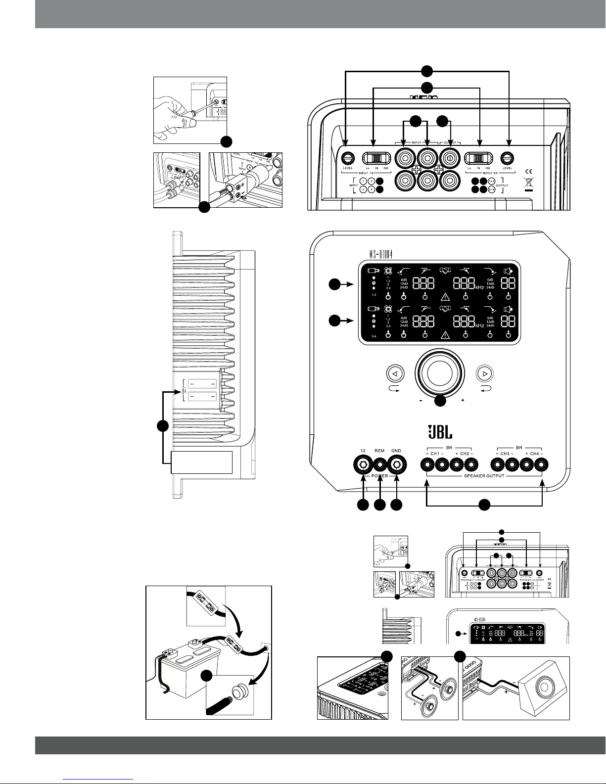
1Input-Level Control
Used to match the input sensitiv-
ity to the signal voltage for proper
analog-to-digital conversion. See
“Setting the Input Level, and En-
abling or Disabling Signal-Sensing
Turn-On” for details. DO NOT use
these controls for setting the relative
output level of amplier channels!
2Input Signal Selector
Lo/Hi/Hi2 sets the input
voltage and impedance range. See
“Setting the Input Level, and
Enabling or Disabling Signal-Sens-
ing Turn-On” and “The factory-
installed system in my car shows a
‘speaker disconnected’ message,
or it fails to play when a speaker is
disconnected or when an amplier
is connected to its output. What
should I do?” for details.
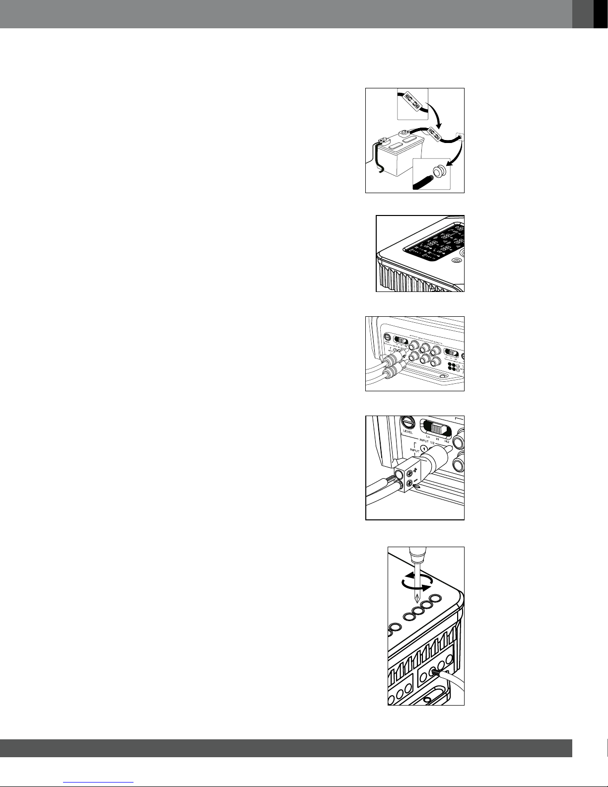
Audio Inputs
Use RCA audio cables for preamp-
level connections or the included
RCA-to-bare-wire adapters for
speaker-level input connections.
4
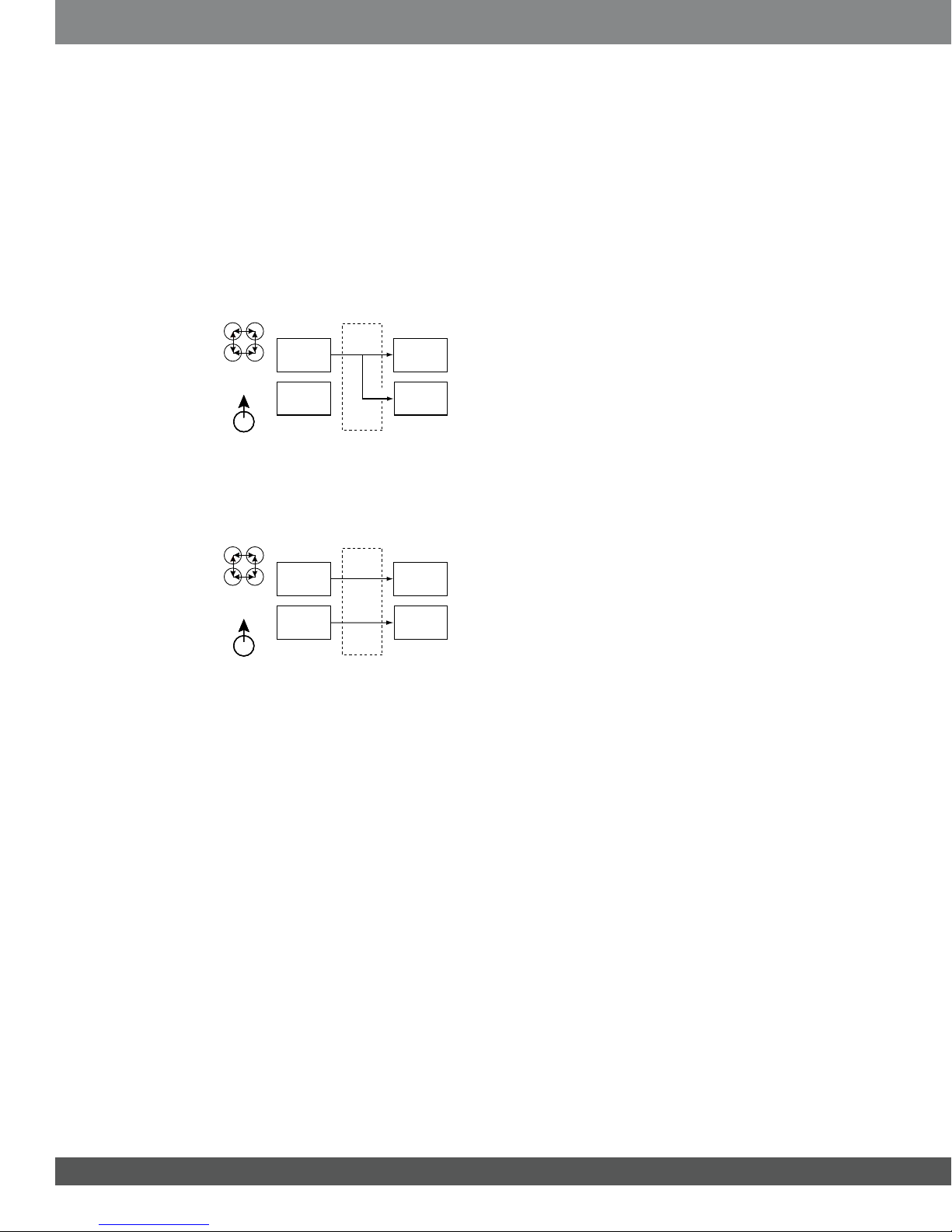
Summed Pass-Through Outputs
Input channels 1 and 3 are com-
bined and sent to one output.
Inputs 2 and 4 are combined and
sent to the other output.
5Onboard Fuses
2 x 30A ATC type.
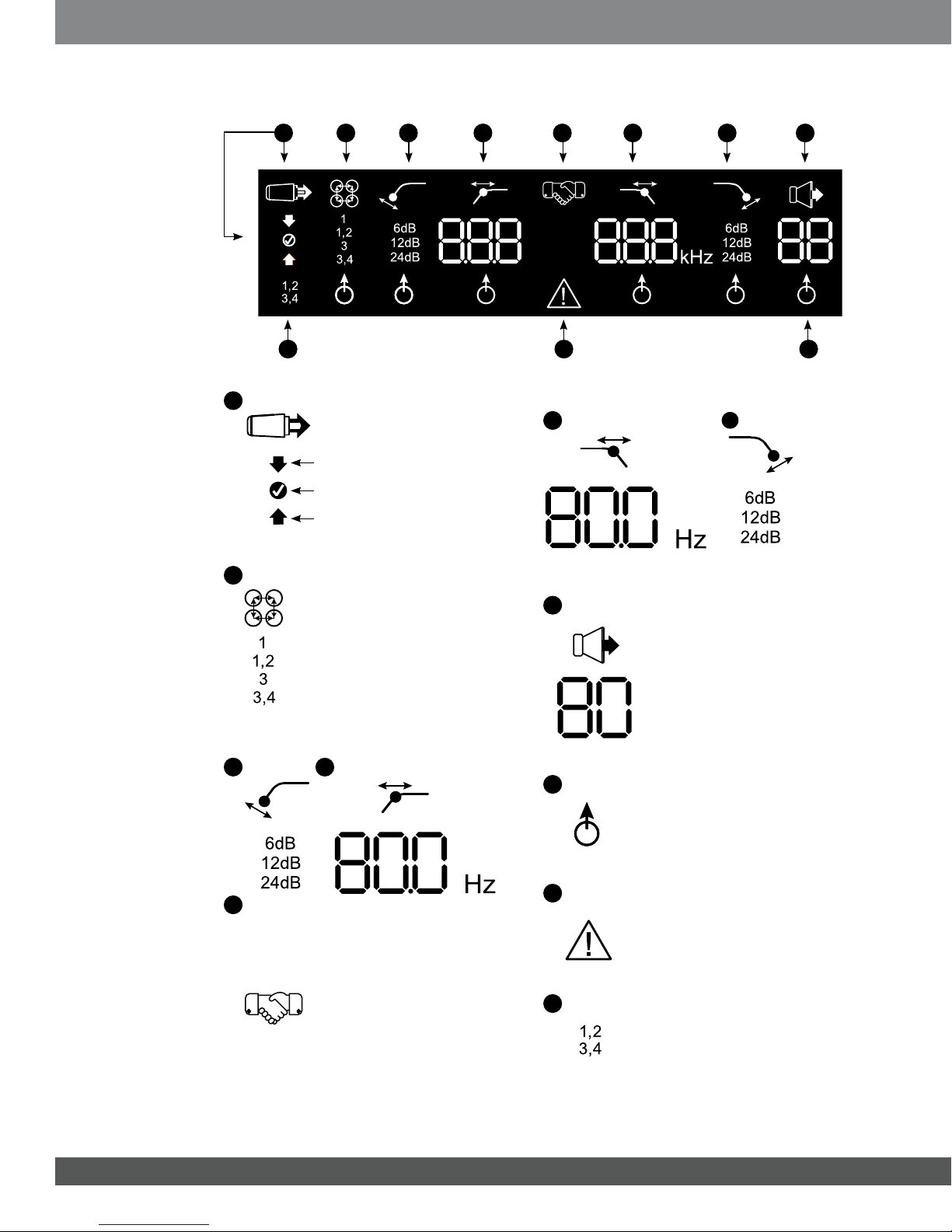
6
Channels 1 and 2 Display Panel
Displays the settings of channels 1
and 2 of the amplier.
7
Channels 3 and 4 Display Panel
Displays the settings of channels 3
and 4 of the amplier.
8User Controls
Allows adjustment of amplier set-
tings. See “MS-A1004 User
Controls” for details.
9+12V Power Input
Connect to vehicle battery with a
60A fuse within 18 inches (45.7cm)
of the positive battery terminal.
10 Remote Turn-On Input
Connect switched +5V to +12V.
NOTE: The MS-A1004 also in-
cludes signal-sensing turn-on. You
may choose the turn-on method
during setup. See “How does the
digital input mixer work?” and “MS-
A1004 Connections” for details.
11 Chassis Ground Input
Connect to a paint-free spot on the
vehicle chassis.
12 Speaker Outputs
MS-A1004 FEATURES
3