JBL MS-A5001 User manual

USER GUIDE
MS-A5001
Digital signal processing amplier

1
2
34
40 A
40 A
2X40A
2 x 40A
+
-
1 x 80A
1
3
6
5
8
8
910
10
11
11
2

1Input-Level Control
This control is used to match
the input sensitivity to the signal
voltage for proper analog-to-
digital conversion. See page 7 for
details. DO NOT use this control
to set the relative output level of
amplifier channels!
2Input Signal Selector
Lo/Hi/Hi2 sets input voltage and
impedance range. See page 7 for
details.
Audio Inputs
Use RCA audio cables for
preamp-level connections or
attach the included RCA to bare
wire adapters for speaker-level
input connections.
4
Pass-Through Outputs
Input channel 1 sends signals to
Output 1. Input channel 2 sends
signals to Output 2. The
MS-A5001’s filter settings do not
affect these channels.
5Onboard Fuses
2 x 40A ATC type.
6
Display Panel
Displays the amplifier’s settings.
7
User Controls
These controls allow you to adjust
the amplifier’s settings. See page
9 for details.
8+12V Power Input
Connects to your vehicle’s battery
with a 80A fuse within 18 inches
(45.7cm) of the battery’s positive
terminal.
9Remote Turn-On Input
Connects switched +5V to
+12V. Note: The MS-A5001 also
includes signal-sensing turn-on.
You may choose the turn-on
method during setup. See pages
5 and 9-10 for details.
10 Chassis Ground Input
Connect to a paint-free spot on
the vehicle chassis.
Speaker Outputs
Two mono speaker outputs.
These outputs send the same
output signal (in parallel) for
the added convenience of
connecting multiple subwoof-
ers. Be sure to account for
parallel resistance connections
when you determine the load on
the MS-A5001’s output. Do not
connect loads below a total of
two ohms.
MS-A5001 FEATURES
3
11
3
FCC REGULATIONS
FCC INFORMATION FOR USERS
This device complies with Part 15 of the FCC Rules. Operation is subject to the following two conditions: (1) This device may
not cause harmful interference; and (2) this device must accept any interference received, including interference that may
cause undesired operation.
RADIO AND TELEVISION INTERFERENCE
This equipment has been tested and found to comply with the limits for a Class B digital device, pursuant to Part 15 of the
FCC Rules. These limits are designed to provide reasonable protection against harmful interference in a residential installation.
This equipment generates, uses and can radiate radio frequency energy and, if not installed and used in accordance with the
instructions, may cause harmful interference to radio communications. However, there is no guarantee that interference will
not occur in a particular installation. If this equipment does not cause interference to radio or television reception, which can
be determined by turning the equipment off and then on, the user is encouraged to try to correct the interference by one or
more of the following measures:
• Increase the separation between the equipment and receiver.
• Connect the equipment to a different outlet so that the equipment and receiver are on different branch circuits.
• Consult the dealer or an experienced radio/TV technician for help. Changes or modications not expressly approved
by JBL could void the user's authority to operate the equipment.
IC STATEMENT AND WARNING
This Class B digital apparatus complies with Canadian ICES-003. Cet appareil numérique de la classe B est conforme à la
norme NMB-003 du Canada.
IMPORTANT NOTE FOR ALL ELECTRONIC PRODUCTS:
Before inserting or unplugging audio cables from the source device's headphones or line-level output jacks, it is good
practice to turn off the device rst. This will prolong the life of your unit, help protect your device from static electricity
and prevent potential damage.
MS-A5001
DIGITAL SIGNAL-PROCESSING AMPLIFIER
PLEASE READ THIS BEFORE YOU BEGIN!
JBL®MS-series amplifiers include many features not found on conventional car-audio amplifiers. As a result, the setup
procedure for JBL MS-series amplifiers is different from that of conventional car-audio amplifiers. The following
overview of features and functions will help you plan a great system and make the best use of the MS-A5001’s
innovative features.
About the digital signal processing (DSP) included in MS-series amplifiers:
All of the signal processing in MS-series amplifiers is digital. Digital signal processing, along with the amplifiers’ intuitive
controls and display, make precise setup easy. Only the input-level controls are analog.
Will I lose my settings if I disconnect the amplifier or the car’s battery?
No. The MS-A5001 stores all of the DSP settings in nonvolatile memory, so you will not lose any settings if power
is removed.
Why are the input-level controls analog?
In order to provide the best signal-to-noise ratio and to maximize the resolution of the digital-to-analog conversion,
the maximum input-signal level to the analog-to-digital (A/D) converters must be precisely set. The control that sets
the level must be an analog control. The included setup CD and the procedure described in this manual make setting
the level simple and precise. Once you set the input-level control, do not use the control to “tune” the system. Use the
digital output-level control to adjust the relative level between amplifier channels to tune the system.

Why are the signal inputs and speaker outputs numbered rather than labeled “right” and “left”?
MS-series amplifiers are designed to make integration into any system simple and straightforward. The ampli-
fier includes a digital input-mixer control that eliminates the need for Y adapters. It allows a mono or stereo
signal to drive any pair of output channels for maximum system-building flexibility. Labeling the channels “left”
and “right” would be confusing in some applications.
How does the digital input mixer work?
The MS-A5001 converts the signals from each RCA-type input connector into digital signals and sends them
to its digital signal processor. The DSP routes the signals to the speaker output according to the selections
in the input mixer. There’s one input mixer for channels 1 and 2 that feeds the mono output channel. Select-
ing “1” in the input mixer for channels 1 and 2 will send only the signal connected to input jack 1 to the mono
output channel. Use this setup if the subwoofer input is already mono or if the intended signals come from
only one channel. (See Figure 1.)
Figure 1
Selecting “1.2” in the input mixer sends a summed mono signal to the output. This selection is useful for send-
ing a stereo signal to the mono output when using subwoofers intended to receive information from both the
left and right inputs. (See Figure 2.)
Figure 2
Many system configurations are possible. None of them need Y adapters. See “System Diagrams” (pages 12
and 13) for more examples.
Does the amplifier include speaker-level and line-level inputs?
Yes. MS-series amplifiers can accept any input signal. If your head unit includes RCA-type outputs, simply plug
them into the RCA-type input jacks. If your head unit doesn’t include RCA-type outputs (as is the case with
all factory-installed systems), use the included RCA-to-bare-wire adapters. Be sure to observe proper polarity.
The signal inputs are differential and will accept any signal from 100mV (low-level) to 20V (high-level). There’s
no need to use separate adapters or to determine the signal voltage or type precisely. MS-series amplifiers’
on-board tools and the setup procedure described later in this manual will make optimizing the configuration
simple.
The factory-installed system in my car shows a “speaker disconnected” message or fails to play
when a speaker is disconnected or when an amplifier is connected to its output. What should I do?
MS-series amplifiers include three input-level switch positions: Lo, Hi and Hi2. The Hi2 position includes a
circuit designed to fool the factory system into “seeing” a speaker connected to its output. If your car has one
of these systems, set the input level control to “Hi2” and follow the rest of the setup instructions.
Input 1
Input 2
Input 1
Input 2
Output
DSP
1
Input 1
Input 2
Input 1
Input 2
Output
DSP
1,2
4

My factory-installed head unit doesn’t include a remote-turn-on wire. What should I do?
MS-series amplifiers include signal-sensing turn-on. They never require a remote turn-on connection. The amplifier
will sense the presence of an audio signal on its inputs, and it will turn on automatically. A few minutes after the
signal stops or after the vehicle’s radio is turned off, the amplifier will turn itself off automatically. During the delay,
the amplifier draws very little current so that it won’t drain the vehicle’s battery.
What is the best procedure for choosing a crossover frequency and slope? (Figures 3a & 3b)
A crossover is a pair of filters that divide the audio signal into low frequencies (bass) and high frequencies (treble)
so each band of frequencies goes to the speaker designed to play it. For example, a tweeter is designed to play
only high frequencies, and too much bass can damage it. A woofer is designed to play only low frequencies and
does a poor job of reproducing high frequencies. A midrange speaker is designed to play frequencies between
bass and treble (midrange frequencies). Figure 3a shows how these speakers would be divided up across
the 20Hz – 20kHz range using the appropriate filters (that is, the appropriate crossovers).
Figure 3a Figure 3b
When setting a crossover between a low-frequency speaker and a high-frequency speaker, choose the high-pass
filter (HPF) frequency that will keep the high-frequency speaker safe. Set the low-pass filter (LPF) so the hand-off
provides smooth response in the region near the crossover frequency. When implementing a crossover between
speakers, use steep (24dB/octave) slopes for both filters to maximize the amount of low frequencies that the
high-frequency speaker can handle safely and to minimize the interaction of the sound between the low-frequency
speaker and the high-frequency speaker. Figure 3b shows the differences of 6, 12 and 24dB/octave filter slopes.
If I should use 24dB/octave slopes for crossovers, why do MS-series amplifiers include 6dB and 12dB/
octave slopes too?
If your MS-series amplifier will power a subwoofer in a vented (ported) box, use a 12dB/octave high-pass filter
to protect the subwoofer from damage by limiting the amount of bass below the box’s tuned frequency that the
amplifier sends to the subwoofer. A 6dB/octave high-pass filter can be useful in slightly limiting the amount of bass
that the amplifier sends to full-range speakers in systems that don’t use a subwoofer, limiting the amount of high
frequencies that the amplifier sends to rear speakers.
Why does each pair of channels include a high-pass filter (HPF) and a low-pass filter (LPF)?
In some systems, it can be useful to limit the high frequencies and the low frequencies that an amplifier sends to
a speaker. Use the HPF and the LPF together to create a band-pass filter for a subwoofer, including a subsonic
filter as described below. When using the filters to create a band-pass filter, the HPF can never be set to a higher
frequency than the LPF. For example, if the LPF is set to 80Hz, the HPF can be set to any frequency below 80Hz.
This protection prevents errors in setup.
Do MS-series amplifiers include a subsonic or infrasonic filter for use with vented enclosures?
Yes. If you want to use a subsonic or infrasonic filter with your subwoofer, configure the channel’s crossover as a
band-pass filter. The low-pass filter will limit the high frequencies that the amplifier sends to the subwoofer, and
the high-pass filter will be the infrasonic filter. Set the high-pass filter frequency about 10Hz below the frequency at
which the enclosure is tuned, and use a 12dB/octave slope (see Figure 4).
Figure 4
20 Hz 50 100 200 500 1K 2K 5K 10K
-21
-18
-15
-12
-9
-6
-3
0
3
6
9
Low-Pass
Filter
Band-Pass
Filter
High-Pass
Filter
20 H z 50 100 200 500 1K 2K 5K 10K
-21
-18
-15
-12
-9
-6
-3
0
3
6
9
6dB/oct.
12dB/oct.
24dB/oct.
10 Hz 20 50 100 200 500 1K 2K 5K 10K
-27
-24
-21
-18
-15
-12
-9
-6
-3
0
3
Subsonic
Filter
Low-Pass
Filter
5

About the wireless bass control (MS-WBC, sold separately):
The MS-series wireless bass control can make installation easy. The circuit is designed for long battery life; a
separate, wired connection to +12V is included for those who never want to replace the battery. The wireless
bass control does not need a wired connection to the amplifier. The control sends a radio signal to the DSP in
the amplifier; as a result, the control may be mounted in a console or under the dash, and the amplifier may be
mounted in the trunk or hidden behind a panel.
The amount of bass included in recordings varies greatly, and the ability to adjust the amount of bass between
songs or albums is useful. Unlike conventional remote bass controls, the MS-WBC doesn’t simply increase the
level of the amplifier’s channels that are connected to the subwoofer. Conventional bass controls adversely affect
the crossover between the subwoofer and the midbass or midrange speakers any time they are adjusted. This
arrangement causes the bass to sound boomy or muddy when it’s boosted, and it draws the listener’s attention
to the subwoofer’s location. (See Figure 5a.)
Figure 5a
The bass-boost filter in the MS-series amplifiers is a shelf filter that boosts or cuts bass below 60Hz but never
above 160Hz. The range of adjustment is +/–10dB. Additionally, the bass boost or cut is sent to all the ampli-
fiers with which the control is paired. The bass control works with the crossover filters to ensure that the amplifier
sends the proper amount of boost or cut to the subwoofer and the midbass or midrange speakers so the
character and apparent location of bass sounds remain constant. See Figure 5b for the performance of the
MS-WBC over the conventional bass controls as would appear in Figure 5a.
Figure 5b
Read this before starting installation!
1) JBL MS-series amplifiers include many features not found on conventional car-audio amplifiers. As a result, the
setup procedure for JBL MS-series amplifiers is different from that of conventional car-audio amplifiers. Care-
fully read and understand these instructions before attempting installation.
2) At the installation sites, locate and make a note of all fuel lines, hydraulic brake lines, vacuum lines and
electrical wiring. Use extreme caution when cutting or drilling in and around these areas.
3) Choose a mounting location for the amplifier inside the passenger or cargo area that will ensure that the
amplifier will have no exposure to moisture. Never mount an amplifier outside the car or in the engine
compartment.
4) Make sure that there is sufficient air circulation at the mounting location for the amplifier to cool itself.
5) Mount the amplifier securely.
10 Hz 20 50 100 200 500 1K 2K 5K 10K
-18
-15
-12
-9
-6
-3
0
3
6
9
12
Crossover Frequency
Changes With Bass Boost
10 Hz 20 50 100 200 500 1K 2K 5K 10K
-18
-15
-12
-9
-6
-3
0
3
6
9
12
Crossover Frequency
Constant With Bass Boost
CAUTION: Installation of car-audio components requires experience in performing mechanical and electrical procedures. If
you feel you lack the required experience or necessary tools, please have a qualified professional technician install your
amplifier.
CAUTION: Before installation, disconnect the negative (–) battery terminal to prevent damage to the unit and to prevent the
battery from being drained while you work on the car.
6

MS-A5001 CONNECTIONS
Power Inputs
1. +12V Power Input
Connect this input to the vehicle’s battery using a minimum size of 8 AWG
(8mm²) wire with a 80A fuse placed within 18 inches (45.7cm) of the positive
battery terminal. Use an insulation grommet at every location where the
power wire will pass through metal.
2) Remote Turn-On Input (Optional to Connect)
No discrete remote turn-on connection to the MS-A5001 is necessary. If
your head unit includes a remote turn-on lead and you wish to connect it,
connect it to this terminal.
3) Chassis Ground Input
Using at least 8 AWG (8mm²) wire, connect this terminal to a nearby point
of the vehicle’s chassis (sheet metal). Scrape away the paint from the area
to ensure a good connection. Do not ground the amplifier to the vehicle’s
frame.
Audio Inputs
1) Using RCA Outputs
If the unit that precedes this amplifier in the signal chain includes RCA-type
output connectors, connect them directly to the amplifier’s RCA inputs.
2) Using Speaker-Level Signals
If the equipment that precedes this amplifier doesn’t have RCA-type con-
nectors, use the RCA-to-bare-wire adapters included with the amplifier
(pictured at right). Connect the signal + to the terminal marked “+” and the
signal – to the terminal marked “–”.
Pass-Through Audio Outputs (Full Range)
This amplifier sends input channels 1 and 2 to the corresponding RCA
outputs. Using these outputs, you can easily add additional amplifiers. For
example: When using the MS-A5001 for a subwoofer, you could use these
outputs for a second subwoofer amplifier or a high-frequency amplifier to
complete a system. The outputs are full-range, based on the input signal.
No high-pass or low-pass filters are applied in the MS-A5001 to these
outputs.
Speaker Outputs
Connect each speaker to the amplifier + and – terminals. See page 9 (“Set-
ting the Input Mixer”) to learn how to assign the input signals to the output
channel. Observe proper polarity when connecting the speakers to the
outputs.
1) Single Connection
Connect the + and – terminals to either + and – speaker output terminal.
They are connected internally so the signal is available on either terminal.
2) Dual Connection
Connect the + and – of each speaker to one + and – terminal at the ampli-
fier. This arrangement is intended for easy connection of dual subwoofers or
a dual voice-coil subwoofer using parallel voice coils.
See pages 12 and 13 for examples of the most common system configura-
tions for this amplifier.
+
-
1 x 80A
7

MS-A5001 DISPLAY ICONS
1234 5 678
kHz
6dB
12dB
24dB
6dB
12dB
24dB
1
1,2
!
1,2
kHz
34
5
8
9
10
11
1
2
Input Setup Mode Active
Input Sensitivity Too High
Input Sensitivity Too Low
Input Sensitivity Correct
Input-Level Settings
1
1,2
Input Mixer
Input-Channel Mixer
Indicates which signal
inputs are selected to
feed the mono output.
High-Pass Filter
6dB
12dB
24dB kHz
Slope Frequency
6 7
Low-Pass Filter
6dB
12dB
24dB
kHz
SlopeFrequency
Pairing Confirmation
Bass Level Controller Pairing*
*MS-WBC Wireless Bass
Controller is an optional
accessory.
Output Gain
Adjustment
Output Gain
Adjustment Active*
Adjustment-
Selection
Indicator
Protection
!
Output Gain
Level (0 to 80)
*Muted when in
“Setup Mode”
Amplifier
Protection Circuit
Engaged
When lit, the parameter
above is selected for
adjustment.
Channel ID
Indicates the amplifier
channels affected by the
row of settings to the right
in the display.
(As the MS-A5001 is a
mono amplifier, only two
possible input
channels exist.)
Use as a subsonic filter on the
MS-A5001.
This setting does not affect
pass-through output.
11 10 9
8

MS-A5001 USER CONTROLS
MS-A5001 SETTINGS GUIDE
INITIAL SETUP
Activating the Controls
Press both CCW and CW buttons at the same time for less than
three seconds, and release the buttons to activate the controls.
The adjustment-selection indicator will light up. Use the CCW and
CW buttons to move the indicator to the parameter that you wish to
adjust. After you’ve made your adjustments, and the controls have
been inactive for more than 30 seconds, the selection-indicator light
will go out, and the controls will become deactivated to prevent
unintentional adjustment of the amplifier’s controls.
Setting the Input Mixer
Once the controls are active, press the CW or CCW button until the input mixer
is selected for channels 1 and 2. Turn the rotary control to select the input
connector(s) that will feed output channels 1 and 2.
See “System Diagrams” on pages 12 and 13 for practical examples.
Setting the Input Level, and Enabling or Disabling Signal-Sensing Turn-On
BEFORE YOU BEGIN
If the factory-installed system to which you have connected your MS-series amplifier
shows a “speaker disconnected” error message or fails to provide an output signal, move
the input-level switch to the Hi2 position. You may need to turn the vehicle or the factory-
installed head unit off and then back on to reset the error message.
NOTE: DO NOT USE THE Hi2 SETTING WITH THE RCA OUTPUTS
OF AFTERMARKET HEAD UNITS!
Counterclockwise
(CCW) Button
Move selectable op-
tion counterclockwise
(CCW) one value.
Clockwise
(CW) Button
Move selectable
option clockwise
(CW) one value.
Rotary Encoder
Rotates clockwise (CW) and counterclockwise (CCW). Each
detent represents a value increase (CW) or decrease (CCW).
Mode Access Control
Pressing both the left and right buttons simul-
taneously for specified time periods accesses
various modes of the amplifier.
9

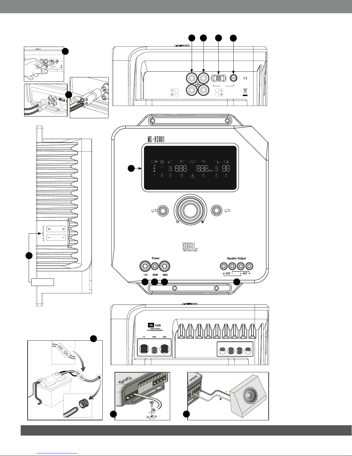
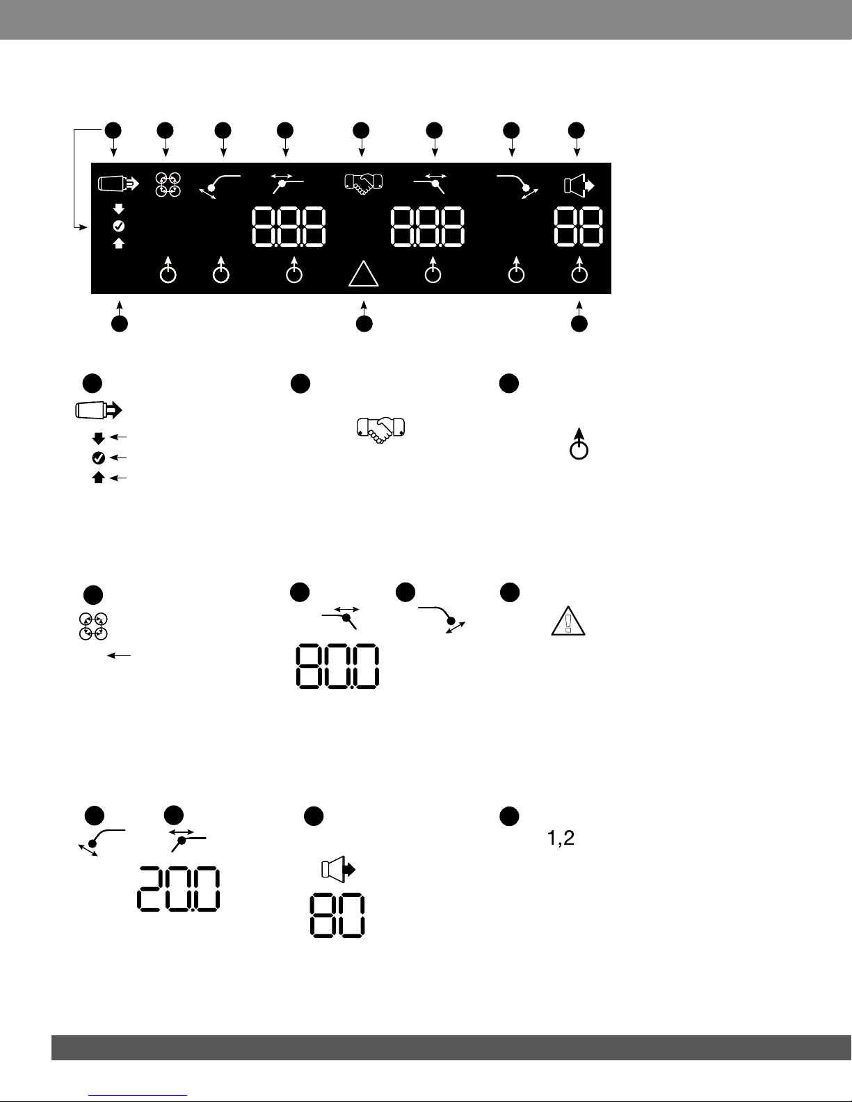
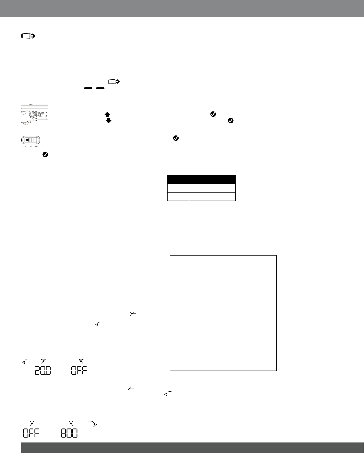
To Set the Input Level:
1. Move the input-level control to the Hi position (or Hi2 if you are connecting to a factory-installed sys-
tem with open-circuit protection).
2. Set the bass, treble, balance and fader controls on your head unit to the center (or flat) positions. Set
“loudness” to off. Defeat any sound-enhancement settings (such as DSP, surround sound
or EQ).
3. Insert the setup CD into your head unit and verify that the CD is playing.
4. Enter the setup mode by pressing CW and CCW buttons simultaneously for more than three seconds
until the input-level adjustment icon illuminates. The amplifier’s output will be muted (output-
level indicator will show “ ” in the display).
5. Turn the head unit’s volume control all the way up (to maximum output).
6. Using a small screwdriver on the level-adjustment dial next to the input switch, adjust the input-level
control up or down while watching the icons on the amplifier’s display panel.
If the green “up” arrow icon is lit, turn the control clockwise until the icon lights up.
If the red “down” arrow icon is lit, turn the control counterclockwise until the icon
lights up.
Note: If turning the control fully clockwise doesn’t cause the icon to light, move the input-
level control to the “Lo” position and try again.
Once the icon lights up, stop adjusting. Repeat the procedure for the input-level control on the other
channels. When both check marks light up, you have properly set the input levels for each channel pair.
To Enable or Disable Signal-Sensing Turn-On:
7. While in setup mode, enable or disable signal-sensing turn-on
by turning the Rotary Control clockwise or counterclockwise to
select “SEn On” or “SEn OFF” in the display. If you have
connected a remote turn-on lead, set to “SEn OFF.”
8. Turn the volume control on your head unit down and remove
the setup CD. If you miss or circumvent this step, the audio system will reproduce a loud test signal
that could damage your speakers when you exit the setup mode.
9. Press and release the CW and CCW buttons simultaneously to exit the setup mode.
10.Do not adjust the input-level controls further. Use the output-level control to balance the channel
levels and to “tune” the system.
SETTING THE FILTERS (CROSSOVERS)
There are 98 selectable frequencies for the low-pass and
high-pass filter settings. The selectable frequencies are detailed
in the table to the right.
Getting to the Crossover Settings
Press both CCW and CW buttons at the same time for less
than three seconds; release the buttons to activate the controls.
Use the CCW and CW buttons to navigate to your preferred
crossover-adjustment parameter.
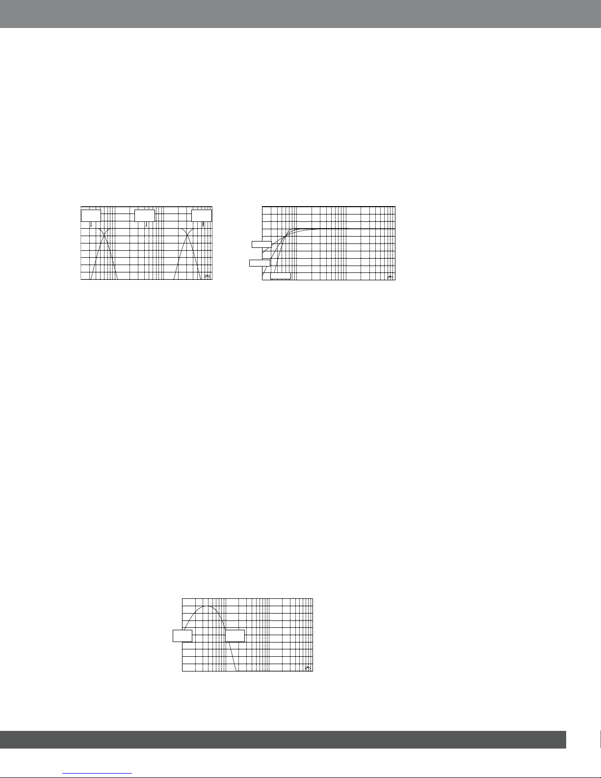
How to Set a High-Pass Filter
Navigate to the high-pass lter frequency parameter. Using the
rotary encoder, select the desired cutoff frequency. Then navigate to
the high-pass lter slope parameter and, using the rotary encoder,
select the desired lter slope.
High-Pass Example
Use the CW and CCW buttons to navigate to the low-pass frequency
parameter and set to “OFF.”
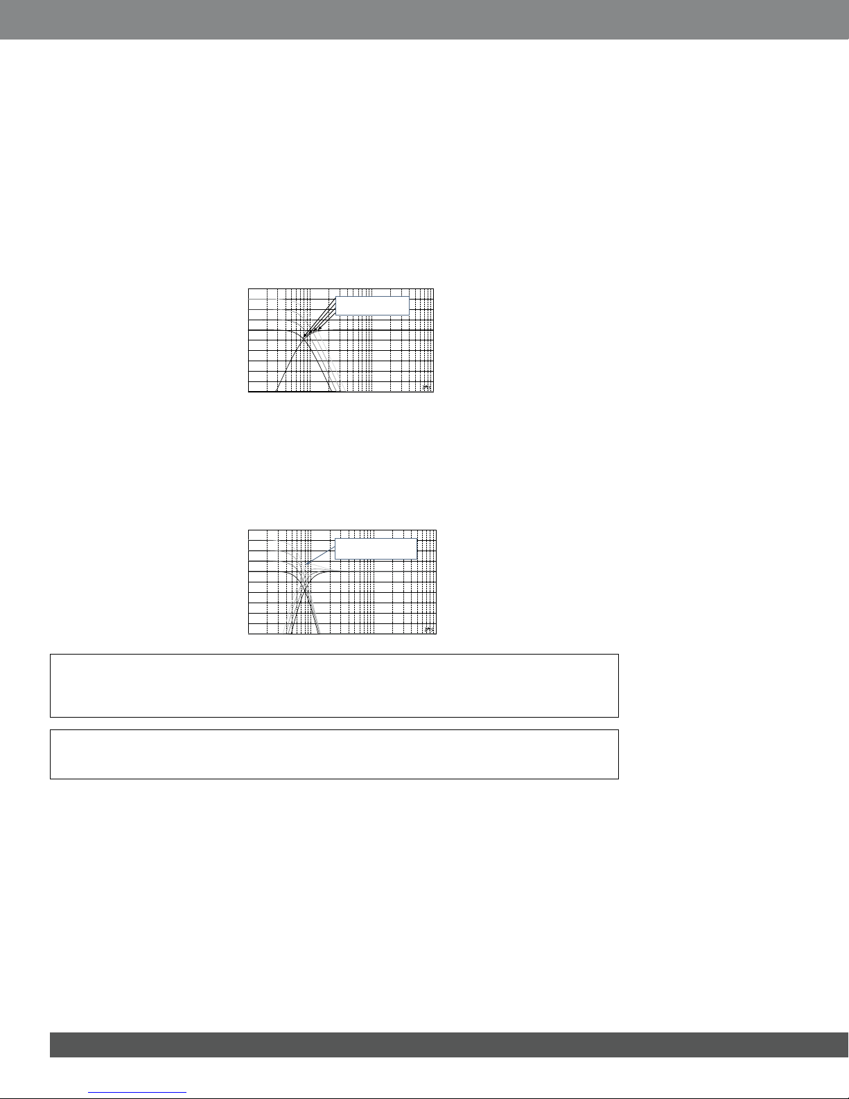
How to Set a Low-Pass Filter
Navigate to the low-pass lter frequency parameter and, using the rotary encoder, select the desired
cutoff frequency. Then navigate to the low-pass lter slope parameter and, using the rotary encoder,
select the desired lter slope.
Low-Pass Example
Use the CW and CCW buttons to navigate to the high-pass frequency parameter and set to “OFF.”
Mode Function
SEn On Signal Sensing is ON
SEn OFF Signal Sensing is OFF
Available Crossover Frequency Settings
20.0Hz 40.0Hz 60.0Hz 80.0Hz 100Hz
21.0Hz 41.0Hz 61.0Hz 81.0Hz 101Hz
22.0Hz 42.0Hz 62.0Hz 82.0Hz 102Hz
23.0Hz 43.0Hz 63.0Hz 83.0Hz 103Hz
24.0Hz 44.0Hz 64.0Hz 84.0Hz 104Hz
25.0Hz 45.0Hz 65.0Hz 85.0Hz 105Hz
26.0Hz 46.0Hz 66.0Hz 86.0Hz 106Hz
27.0Hz 47.0Hz 67.0Hz 87.0Hz 107Hz
28.0Hz 48.0Hz 68.0Hz 88.0Hz 108Hz
29.0Hz 49.0Hz 69.0Hz 89.0Hz 109Hz
30.0Hz 50.0Hz 70.0Hz 90.0Hz 110Hz
31.0Hz 51.0Hz 71.0Hz 91.0Hz 115Hz
32.0Hz 52.0Hz 72.0Hz 92.0Hz 120Hz
33.0Hz 53.0Hz 73.0Hz 93.0Hz 125Hz
34.0Hz 54.0Hz 74.0Hz 94.0Hz 130Hz
35.0Hz 55.0Hz 75.0Hz 95.0Hz 135Hz
36.0Hz 56.0Hz 76.0Hz 96.0Hz 140Hz
37.0Hz 57.0Hz 77.0Hz 97.0Hz OFF
38.0Hz 58.0Hz 78.0Hz 98.0Hz
39.0Hz 59.0Hz 79.0Hz 99.0Hz
kHz
24dB
kHz
24dB
10

How to Set a Band-Pass Filter Band-Pass Example
To build a proper band-pass filter, the low-pass frequency
must be greater than the high-pass frequency. The MS-A5001
will not allow you to set the low-pass filter frequency to a
lower value than the high-pass filter frequency. To enable
a band-pass filter, first select the high-pass filter frequency and slope as indicated above. Next, select
the low-pass filter frequency and slope. Once the settings are complete, the controls will time out after
15 seconds.
OUTPUT LEVELS
Setting the Output Level
Use the output-level control to adjust the balance between the subwoofer and the full-range speakers,
between the front and rear speakers, or between the midrange, mid-bass or tweeters in a bi-amped or
tri-amped (all active) system. The output level is adjustable in 0.5dB increments, with a display of 80
indicating maximum output. The lowest setting will mute the output and “ ” will show in the
display.
To set the output level, press the CW or CCW buttons to highlight the output-level parameter for adjustment, and
turn the rotary controller to adjust the output level.
WIRELESS BASS CONTROL
Overview MS-WBC
The MS-WBC wireless bass control (sold separately) is battery-powered;
it also includes a +12V plug that can be connected to a +12V source in your
vehicle. The MS-WBC transmits a signal only when the control is rotated. The
amplifier(s) must be on to receive and respond to the control. Adjustments
made to the control when the amplifier(s) are off aren’t recognized.
How to Pair the MS-WBC Wireless Bass Control with the MS-A5001
The optional MS-WBC wireless bass controller must be paired to the amplifier
in order to be used. When the amplifier is first turned on, it is not paired with any
controller.
Press and hold both CCW and CW buttons simultaneously for more than three sec-
onds and the amplier will enter Setup mode. Continue pressing the buttons for four
more seconds until the pairing indicator is illuminated. Release the CCW and
CW buttons.
Pairing must occur within 15 seconds. The time remaining is indicated at the far
right of the display. Turn the knob on the bass controller during this 15-second
period. The amplifier will recognize the controller, and the controller will
automatically pair the two together.
After a successful pairing, the upper high-pass filter digits will display the bass
controller version number for 3 seconds. Then the amplifier will return to the nor-
mal (Run) mode.
If a valid pairing has not occurred, the amplifier will remain unpaired. After the 15-
second countdown, the amplifier will return to the setup mode.
If your system includes several MS-series amplifiers, pair them one at a time.
Once all the amplifiers are paired and have returned to the normal (Run) mode,
turn the knob to synchronize all of the amplifiers.
kHz
kHz 24dB
24dB
11

Example of lter and input settings for
this conguration
Example of lter and input settings for
this conguration
In this configuration, a single
subwoofer is connected at one of
the MS-A5001 outputs.
A 4-ohm or 2-ohm subwoofer
can be used.
In this confIguration, subwoofers
are connected in parallel at the
dual mono output of MS-A5001.
Four-ohm or 8-ohm subwoofers
should be used.
Inputs can be Channel 1 only or both
Channel 1 and 2, depending upon how
the pass-through output is to be used.
Inputs can be Channel 1 only or both
Channel 1 and 2, depending upon how the
pass-through output is to be used.
SYSTEM DIAGRAMS
Hz
24dB 24dB
1,2
1,2
Hz
Hz
24dB 24dB
1,2
1,2
Hz
12

English
Example of lter and input
settings for this conguration
Example of lter and input
settings for this conguration
Inputs can be Channel 1 only or both
Channel 1 and 2, depending upon how
the pass-through output is to be used.
Inputs can be Channel 1 only or both
Channel 1 and 2, depending upon how
the pass-through output is to be used.
One dual voice-coil (DVC) subwoofer
is shown wired in series. Do not
have less than a 2-ohm load
at the amplifier.
One dual voice-coil (DVC) subwoofer
is shown wired in parallel. Do not
have less than a 2-ohm load
at the amplifier.
SERIES WIRED VOICE COILS
PARALLEL WIRED VOICE COILS
SYSTEM DIAGRAMS (DVC SUBS)
Hz
24dB 24dB
Hz
Hz
24dB 24dB
Hz
13

© 2010 Harman International Industries, Incorporated. All rights reserved. JBL is a trademark of
Harman International Industries, Incorporated, registered in the United States and/or other countries.
CEA is a registered trademark of the Consumer Electronics Association. Features, specications and
appearance are subject to change without notice.
Harman Consumer, Inc.
8500 Balboa Boulevard
Northridge, CA 91329 USA www.jbl.com
Parallel Connection
1
R1
1
R2
1
R3 ...
=
Rt
1
+ +
SPECIFICATIONS
Series Connection Parallel Connection
Power output
CEA®2006
Bridged mode
Signal-to-noise ratio 80dB
106dB
Frequency response 20-270Hz
Maximum input sensitivity
Maximum input voltage
Dimensions (L x W x H)
Weight
Beauty carton dimensions
Gross weight (with beauty carton)
500W RMS x 1 channel @ 4 ohms
500W RMS x 1 channel @ 2 ohms
100mV
20V
7-3/16" x 8-1/4" x 2-3/4"
183mm x 210mm x 70mm
13-15/16" x 11-9/16" x 10-5/16"
354mm x 294mm x 264mm
CALCULATING SPEAKER LOADS
Use these formulas to calculate total series or parallel resistance of multiple speakers
or voice coils on the MS-A5001 amplier. “R” with a number denotes each nominal
voice-coil impedance (such as R1and R2). Rtis the total combined nominal impedance
presented to the amplier. Never connect loads below a total of 2 ohms.
R
1
R
2
+R
3
...
+=
R
t
Series Connection
Other manuals for MS-A5001
1
Table of contents
Other JBL Car Amplifier manuals

JBL
JBL GTH400 User manual

JBL
JBL Grand Touring Series GTO504 User manual

JBL
JBL Grand Touring Series GTO14001 User manual

JBL
JBL GTO-1004E User manual

JBL
JBL GTS300 User manual

JBL
JBL A6000GTi User manual

JBL
JBL A3000GTi User manual

JBL
JBL gto1201.1 II User manual

JBL
JBL A6000GTi How to use

JBL
JBL GTO7001 User manual