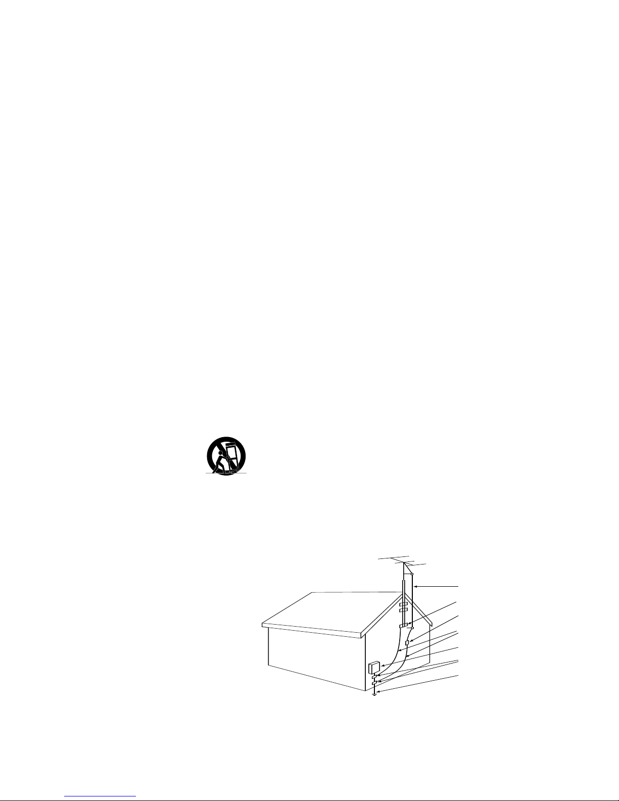
JBL CINEMA VISION CVPD50 User manual

CVR700
HIGH-PERFORMANCE
AUDIO/VIDEO RECEIVER/VIDEO
PROCESSOR/OPTICAL DISC
CHANGER
CVPD50
50-INCH HIGH-DEFINITION
PLASMA DISPLAY
®
OWNER’S GUIDE
JBL CINEMA VISION™SYSTEM
CVR700 OM 12/17/04 4:25 PM Page 117

JBL CINEMA VISION™SYSTEM: CVPD50 HIGH-DEFINITION PLASMA
DISPLAY AND CVR700 CONTROL CENTER WITH AUDIO/VIDEO
RECEIVER, VIDEO PROCESSOR AND OPTICAL DISC CHANGER
4 Important Safety Precautions
5 Introduction
7 Safety Information
10 What’s Included
12 Disc Formats Supported by This Player
13 Terminology
16 CVR700 Front-Panel Controls
19 CVR700 Front-Panel Information Display
20 CVR700 Rear-Panel Connections
24 CVR700R2 Remote Control Functions
32 CVR700R1 Remote Control Functions
39 Installing and Connecting the Equipment
39 Recommended Placement
39 Wall-Mounting the CVPD50 Plasma Display
39 Installing the CVPD50 Plasma Display on the Included
Credenza Stand
40 Important Safety Notes
40 Important Information About the CVPD50 Plasma Display
42 Basic Installation
45 System Configuration
46 Source Configuration
48 Speaker Configuration
48 Configuring Speaker Sizes
49 Speaker Crossover Configuration
50 Speaker Distances
50 Output Level Adjustment
51 Using EzSet
51 Manual Output Level Adjustment
52 Advanced Settings
52 Front-Panel Brightness
52 Volume Default
53 Main Menu Timeout
53 Fan Speed
53 Lip Sync
53 DVD Setup
54 Parental Control
55 Screen Setup
55 Inputs and Picture-in-Picture Settings
56 Picture Settings
57 Display Settings
57 Advanced Settings Menu
58 4:3 Scaling
58 Information Menu
59 Basic Operation
59 Turning the CVR700 and CVPD50 On or Off
59 Source Selection
59 Volume Control
60 Surround Mode Selection
60 Digital Audio Playback
60 Dolby Digital
60 DTS
61 Selecting a Digital Source
61 Digital Bitstream and Surround Mode Indicators
61 PCM Playback
61 Speaker/Channel Indicators
62 Audio Surround Mode Chart
63 Night Mode
63 MP3 and WMA Compressed-Audio Playback
64 Tuner Operation
64 Station Selection
64 Preset Tuning
64 Recording
64 Output Level Trim Adjustment
65 Memory Backup
66 Optical Disc Changer Playback Basics
66 Loading Discs
66 Status Bar
67 Selecting a Disc for Playback
67 JBL On Screen Library™
68 Transport Controls – Playing a Disc
68 Random Play
69 Repeat Play
69 Repeat A-B
70 DVD Playback
70 Using a DVD’s Menu
70 Notes on DVD-Audio Discs
70 Zoom Feature
71 CD Playback
71 Audio CD Playback Features
71 Selecting a Track
71 CD Status Bar
71 Video Off Feature
72 MP3/WMA Playback
72 MP3 or WMA Disc Playback
73 JPEG Playback
74 VCD Playback
74 Using the Status Bar for VCD Playback
74 Playback Control
75 Programmed Play
76 Programming the CVR700R2 Remote
76 Programming Product Codes
76 Preprogrammed Code Entry
77 Automatic Code Entry
78 Learning Commands
79 Changing Devices
80 Macro Programming
81 Recording a Macro
81 Preprogrammed Macros
82 Erasing a Macro
82 Read a Macro
83 Punch-Through Configuration
83 Volume Punch-Through
83 Channel Control Punch-Through
84 Transport Control Punch-Through
84 EzSet Configuration
85 Renaming
85 Renaming a Device
86 Renaming Individual Buttons
87 Resetting the Remote
88 Programmed Device Functions
89 CVR700R2 Remote Function List Table
92 Programming the CVR700R1 Remote
CVR700 OM 12/17/04 4:23 PM Page 2

3
92 Programming Product Codes
92 Direct Code Entry
92 Auto Search Method
93 Learning Codes
93 Erasing Learned Codes
93 Macros
94 Programmed Device Functions
94 Volume Punch-Through
95 Channel Control Punch-Through
95 Transport Control Punch-Through
95 Resetting the Remote Memory
96 CVR700R1 Remote Function List Table
98 CVR700R1 Remote Setup Code Tables
109 Troubleshooting Guide
110 System Reset
111 Technical Specifications
113 Index
See trademark acknowledgements on page 114.
Typographical Conventions
In order to help you use this manual with the remote controls, front-panel controls and
rear-panel connections, certain conventions have been used.
EXAMPLE – (bold type) indicates a specific remote control or front-panel button or
indicator, or rear-panel connection jack
EXAMPLE – (OCR type) indicates a message that is visible on the front-panel
information display or screen
EXAMPLE – (Synchro type) indicates a message that is visible on the CVR700R2
remote’s LCD display
1– (number in a square) indicates a specific front-panel control
a– (number in an oval) indicates a button or indicator on the CVR700R2 remote
control
¡– (number in a circle) indicates a rear-panel connection
A– (letter in a square) indicates an indicator in the front-panel information display
– (number in a triangle) indicates a button or an indicator on the CVR700R1 remote
control
33
34
35
36
37
38
39
40
41
42
43
44
45
46
47
48
49
50
51
52
53
54
55
56
57
38
39
40
41
31
32
30
28
29
25
26
27
28
29
30
24
23
22
21
20
31
37
36
35
34
33
32 31
37
36
35
34
33
32
48
49
50
51
47
46
45
44
43
42
1 2 3 4 5 6
78 9 10 11 12
13 14 15 16 17 18
19 20 21 22 23 24
25 26 27 28 29 30
31 32 33 34 35 36
37 38 39 40 41 42
The exclamation point within an equilateral
triangle is intended to alert the user to the
presence of important operating and
maintenance (servicing) instructions in the
literature accompanying the appliance.
CAUTION
RISK OF ELECTRIC SHOCK
DO NOT OPEN
CAUTION: To reduce the risk of electric shock,
do not remove cover (or back).
No user-serviceable parts inside.
Refer servicing to qualified service personnel.
CAUTION: To prevent electric shock,
do not use this (polarized) plug with
an extension cord, receptacle or other outlet
unless the blades can be fully inserted to
prevent blade exposure.
The lightning flash with arrowhead symbol,
within an equilateral triangle, is intended to
alert the user to the presence of uninsulated
“dangerous voltage” within the product’s
enclosure that may be of sufficient magnitude to constitute
a risk of electric shock to persons.
CVR700 OM 12/17/04 4:23 PM Page 3

4
1. Read these instructions.
2. Keep these instructions.
3. Heed all warnings.
4. Follow all instructions.
5. Do not use this apparatus near water.
6. Clean only with a dry cloth.
7. Do not block any ventilation openings.
Install in accordance with the manufac-
turer’s instructions.
8. Do not install near any heat sources
such as radiators, heat registers, stoves
or other apparatus (including amplifiers)
that produce heat.
9. Do not defeat the safety purpose of
the polarized or grounding-type plug.
A polarized plug has two blades with one
wider than the other. A grounding-type
plug has two blades and a third ground-
ing prong. The wide blade or the third
prong are provided for your safety. If the
provided plug does not fit into your out-
let, consult an electrician for replacement
of the obsolete outlet.
10. Protect the power cord from being
walked on or pinched, particularly at
plugs, convenience receptacles and the
point where they exit from the apparatus.
11. Only use attachments/accessories
specified by the manufacturer.
12. Use only with the cart,
stand, tripod, bracket or
table specified by the manu-
facturer or sold with the
apparatus. When a cart is used,
use caution when moving the cart/appa-
ratus combination to avoid injury from
tip-over.
13. Unplug this apparatus during light-
ning storms or when unused for long
periods of time.
14. Refer all servicing to qualified serv-
ice personnel. Servicing is required when
the apparatus has been damaged in any
way, such as power-supply cord or plug
is damaged, liquid has been spilled or
objects have fallen into the apparatus,
the apparatus has been exposed to rain
or moisture, does not operate normally,
or has been dropped.
15. Do not use attachments not recom-
mended by the product manufacturer, as
they may cause hazards.
16. This product should be operated only
from the type of power source indicated
on the marking label. If you are not sure
of the type of power supply to your
home, consult your product dealer or
local power company. For products
intended to operate from battery power,
or other sources, refer to the operating
instructions.
17. If an outside antenna or cable system
is connected to the product, be sure the
antenna or cable system is grounded so
as to provide some protection against
voltage surges and built-up static
charges. Article 810 of the National
Electrical Code, ANSI/NFPA 70, provides
information with regard to proper ground-
ing of the mast and supporting structure,
grounding of the lead-in wire to an
antenna discharge unit, size of grounding
conductors, location of antenna-dis-
charge unit, connection to grounding
electrodes, and requirements for the
grounding electrode. See Figure A.
18. An outside antenna system should
not be located in the vicinity of overhead
power lines or other electric light or
power circuits, or where it can fall into
such power lines or circuits. When
installing an outside antenna system,
extreme care should be taken to keep
from touching such power lines or circuits,
as contact with them might be fatal.
19. Do not overload wall outlets, exten-
sion cords, or integral convenience recep-
tacles, as this can result in a risk of fire
or electric shock.
20. Never push objects of any kind into
this product through openings, as they
may touch dangerous voltage points or
short-out parts that could result in a fire
or electric shock. Never spill liquid of any
kind on the product.
21. The apparatus shall not be exposed
to dripping or splashing, and no objects
filled with liquids, such as vases, shall be
placed on the apparatus.
22. Do not attempt to service this product
yourself, as opening or removing covers
may expose you to dangerous voltage or
other hazards. Refer all servicing to quali-
fied service personnel.
23. When replacement parts are
required, be sure the service technician
has used replacement parts specified by
the manufacturer or that have the same
characteristics as the original part.
Unauthorized substitutions may result in
fire, electric shock or other hazards.
24. Upon completion of any service or
repairs to this product, ask the service
technician to perform safety checks to
determine that the product is in proper
operating condition.
25. The product should be mounted to a
wall or ceiling only as recommended by
the manufacturer.
read first!
Important Safety Precautions!
Antenna Lead-In Wire
Ground Clamp
Antenna Discharge Unit (NEC Section 810-20)
Grounding Conductors (NEC Section 810-21)
Electric Service Equipment
Ground Clamps
Power Service Grounding Electrode System
(NEC Art. 250, Part H)
Figure A.
Example of Antenna Grounding as per
National ElectricalCode ANSI/NFPA 70
Part No. HCGUL1492/6500 04/2004 EN
CVR700 OM 12/17/04 4:23 PM Page 4

5
INTRODUCTION
Thank you for choosing JBL®. The JBL
Cinema Vision™home theater system is
truly an entertainment system for the
21st century. JBL Cinema Vision is a com-
plete, integrated audio/video system that
combines the sophisticated performance
of separate components with the conven-
ience of a turnkey solution. The system
includes a 50-inch high-definition plasma
display monitor and an audio/video sys-
tem controller that contains a 5-disc
DVD-Audio/DVD-Video/CD changer, high-
performance A/V receiver and a video
processor. The multichannel loudspeaker
system is designed to acoustically, elec-
trically and visually complement the JBL
Cinema Vision source and video compo-
nents. Satellites and the center feature
common voicing, dual-neodymium-driver
satellites, and a 1-inch titanium-laminate
tweeter. The subwoofer features a 400-
watt RMS power amplifier and a 12-inch
cast-basket woofer.
This manual describes the CVR700 con-
trol center, and the CVPD50 50-inch high-
definition plasma display. Together with
the CVSAT50, CVCEN50 and CVSUB50
loudspeakers, the JBL Cinema Vision sys-
tem delivers a complete home theater
experience, including high-quality play-
back of most optical discs.
The CVPD50 and CVR700 have been engi-
neered so that it is easy to take advan-
tage of all of the power of their digital
technology. However, to obtain the maxi-
mum enjoyment from your new home the-
ater system, we urge you to read this
manual. A few minutes spent learning
the functions of the various controls will
enable you to take advantage of all the
power these components are able to
deliver.
If you have any questions about these
products, their installation or operation,
please contact your retailer or custom
installer, as they are your best local
sources of information.
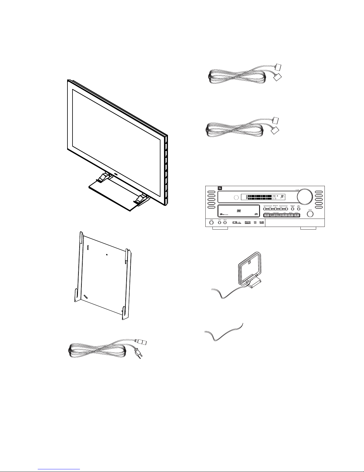
CVPD50 50-Inch High-Definition
Plasma Display Monitor
The CVPD50 is a state-of-the-art, true
high-definition plasma display that may
be used to display HDTV cable or satellite
television signals, as well as movies
played using the CVR700’s internal DVD
changer, or it may be used with a person-
al computer, as well as other external
devices such as video gaming consoles
and recording devices. The sophisticated
processor automatically configures 4:3
video sources for full-screen 16:9 display,
but purists may manually set the proces-
sor to display 4:3 video images without
scaling or adjustment. The CVPD50 offers
stunning picture quality, even under nor-
mal lighting conditions, thanks to its
3,000:1 contrast ratio and 1,000cd/m2
brightness rating. The digital video
processor on board the CVR700 outputs
a digital video signal via a single, propri-
etary connection to the CVPD50 display.
(The CVPD50 display requires the CVR700
control center for operation.)
CVR700 7 x 100 Watts System
Control Center
The CVR700 is a unique multifeatured
component, combining audio and video
source selection and processing with a
five-disc magazine changer capable of
playing DVD-Audio, DVD-Video, CD, CD-
R/RW, DVD+R/RW, DVD-R/RW, MP3,
WMA, Kodak®Picture CD, VCD and JPEG
discs. Video playback using the internal
DVD changer is of the highest quality,
benefiting from pixel-by-pixel processing
and digital output to the plasma display.
The CVR700 is capable of reconstructing
the 3/2 pulldown effect introduced when
film-based programs are transferred to
video. In conjunction with precision video
output DACs, the result is a full 60-frame-
per-second image that is the closest thing
to film this side of your local cinema.
The audio section includes all of the lat-
est surround sound processing formats,
including Dolby* Digital, Dolby Pro Logic*
IIx, Dolby Headphone, DTS®, DTS-ES®,
DTS Neo:6®, DTS 96/24 and Logic 7®.
High-efficiency digital amplifiers are
designed to match the characteristics of
the JBL Cinema Vision speakers, preserv-
ing signal quality and delivering the
power and fidelity you expect from JBL.
In addition to providing a wide array
of listening and viewing options, the
CVR700 is easy to configure so that it
provides the best results for your specific
listening environment and viewing prefer-
ences. On-screen menus make it simple
to customize system settings, on-screen
status banners streamline user interac-
tion, and the EzSet remote automatically
measures and calibrates sound levels
for a perfectly balanced sound field
presentation.
Although the CVR700 is designed to be
used with the internal DVD changer and
CVPD50 display, it also includes a full
complement of inputs and outputs that
are normally found only on standalone
audio/video receivers. It includes
audio/video source inputs for two record-
ing devices, a cable television/satellite
receiver/HDTV tuner, a personal computer
and an auxiliary device. A sixth source
may be connected to the front-panel
jacks, which include not only analog
audio and video inputs, but S-video, com-
ponent video and optical and coaxial digi-
tal audio inputs. A front-panel optical dig-
ital audio output enables recording with
compatible portable devices. Dedicated
rear-panel digital audio inputs (4 optical
and 4 coaxial) are pre-assigned to the
sources, and 2 outputs (1 optical and 1
coaxial) are also provided. An HDCP
(high-definition copy-protected) DVI video
input may be used with a DVI-enabled
HDTV tuner, a satellite or cable set-top
box, or a DVD player, or with a personal
computer featuring a DVI or Analog VGA
video output. A composite video input
may be used with the PIP (picture-in-pic-
ture) function for simultaneous viewing of
two video sources using either a tradi-
tional small screen inset or a split screen.
A universal remote control operates all
devices, and may be programmed to
operate other components in your sys-
tem, such as a VCR, personal video
recorder (PVR), or other devices. The main
remote control is easy to program using
its two-line LCD text display. A second,
simplified remote is also included.
Simple to Install and Use
The JBL Cinema Vision system is
designed for easy installation and simple
operation. Its sophisticated processing
capabilities operate automatically, trans-
parent to the user. The JBL On Screen
Library™display of loaded discs simplifies
navigation and selection of desired pro-
gram material. With state-of-the-art
audio and video components, the JBL
Cinema Vision home theater system is
the perfect combination of the latest digi-
tal audio and video technologies in an
elegant, easy-to-use package.
n50" True high-definition plasma display
with ultrawide viewing angle
n3,000:1 contrast ratio and 1,000cd/m2
brightness
n7 x 100W digital control center with
an audio/video receiver, video proces-
sor and DVD changer
nA wide range of digital and matrix sur-
round modes, including Dolby Digital,
Dolby Digital EX, Dolby Pro Logic II
and IIx, DTS, DTS-ES Discrete and
Matrix, DTS 96/24, DTS Neo:6, Logic 7
CVR700 OM 12/17/04 4:23 PM Page 5
Other manuals for CINEMA VISION CVPD50
1
This manual suits for next models
1
Table of contents
Other JBL Home Theater System manuals

JBL
JBL CINEMA BASE User manual

JBL
JBL Simply Cinema DSC 1000 User manual

JBL
JBL HTI6 Series User manual

JBL
JBL DCR600 II User manual

JBL
JBL HTI6 User manual

JBL
JBL Cinema BD100 User manual

JBL
JBL CS 360 Xcite User manual

JBL
JBL CS 360 Xcite User manual

JBL
JBL Reference 610 Installation and operation manual

JBL
JBL Cinema BD300 User manual