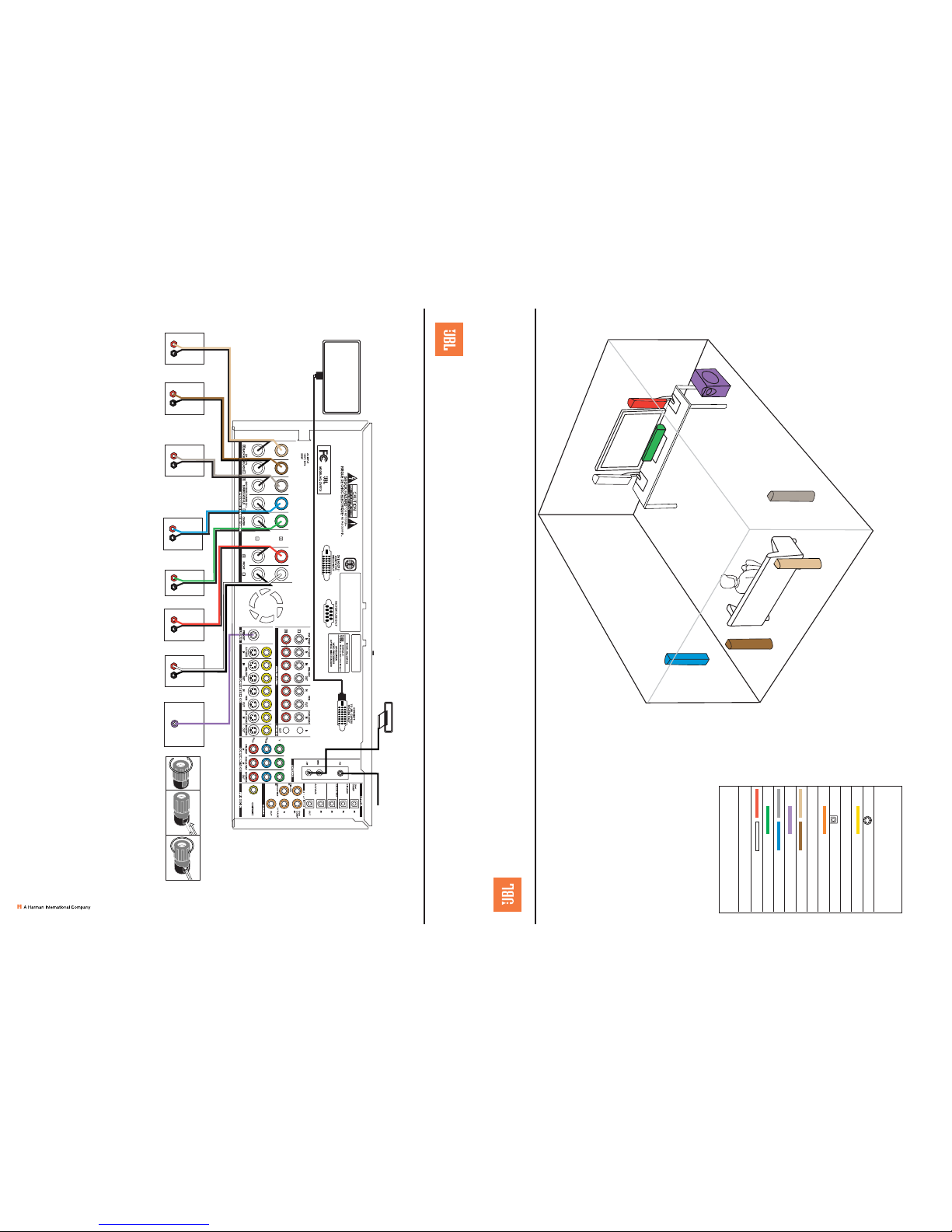
SOURCE COMPONENT CONNECTIONS
Step 5. This step is only required if you have external source devices, including a device
used for watching television, such as an HDTV tuner, a cable television box, a satellite
receiver or a personal video recorder (PVR).
Connect your source devices to the CVR700 as shown in Figure 4. All jacks are perma-
nently assigned to the input sources for which they are named. Therefore, although you
may connect any audio or video device to any source, always make all connections from
a single device to jacks named for the same source. JBL recommends connecting certain
device types to certain sources in order to benefit from the preprogramming of the two
remote controls:
INPUT SOURCE DEVICE TYPES
AUX (TV, HDTV Tuner, VCR/Combo, DVD, CD, Cable, Sat)
VCR (VCR/Combo)
CBL/SAT (Cable, Sat, HDTV Tuner)
GAME/CAM (Game, Camcorder)
DR (DVD-R, CD-R, DVHS, TiVo®, PVR)
DVI/COMP (DVI/DVD, DVI/Cable, DVI/Sat, HD Tuner)
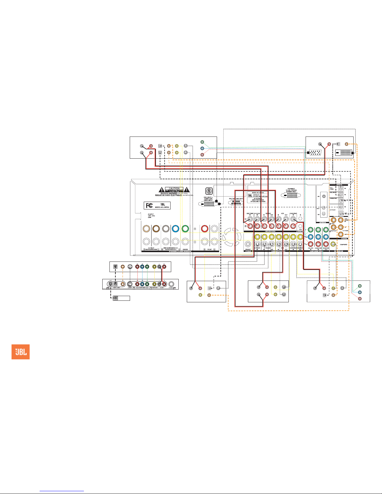
AUDIO connections: Right channel (red) on source to right (red) on CVR700, and left
channel (white) on source to left (white) on CVR700.
DIGITAL AUDIO connections (if available): Choose either coaxial (orange) to coaxial
(orange) OR optical to optical for each device.
VIDEO connections: Choose component (Y/Pb/Pr – green/blue/red), composite (yel-
low) or S-video (4-pin) for each video source. When using component video inputs, the
S-video connection for that source is also required in order to view on-screen menus.
When the on-screen menus are activated while the DVI/Computer source input is in use,
the picture will be temporarily deactivated. Only the digital video interface (DVI) connection
or an analog VGA connection using the supplied cable is available for the DVI/Computer
source. When using PIP, composite (yellow) must be used for PIP jack. When source is
DVI/Comp, PIP is only available as an inset, not split screen. PIP is not available at all
when source is HD component video (480p and better).
When you are not using the CVPD50 screen, or if you desire a second display, connect
the component, composite and S-video Monitor outputs (if used by your sources) to your
video-display monitor or TV. Switch the display’s input to match the type of video used for
the current source.
Basic Configuration
Step 7. See Step 6 on back cover of this guide for final connection sequence.
Step 8. Select digital audio and video inputs for external sources: For external
sources using the analog audio and composite video inputs with 4:3 aspect ratio (e.g.,
VCR), you may skip this step. Press the source selector, then the System selector, then
the OSD button to view the main audio menu. Scroll to Sources and press the Set button
to view the Sources menu. Scroll to the Audio Input line and use the arrow keys to select
the source’s coaxial or optical digital audio input. Scroll to the Video Input line and use the
arrow keys to select the source’s S-video or component video input. Scroll to the Source
A.R. line to indicate 16:9 aspect ratio, which should be used whenever available.
You may not assign one source’s audio or video input to another source (except you
may
assign a video source to the tuner).
The default surround audio mode is Logic 7, with Dolby®Digital and DTS®digital signals
detected automatically. See the owner’s manual for more surround mode options.
Step 9. Configure speakers: If you are using the JBL Cinema Vision loudspeakers, you
only need to specify a 5.1- or 7.1-channel system. Press the OSD button on the remote
to view the main audio menu, then use the arrow keys to scroll down to the System
Configuration line and press the Set button to select it and configure 5.1 or 7.1. For a
7.1 system operation, you must also select the Speakers line in the main menu and
scroll to the Configuration submenu to set the back surround speakers. If you are using
other speakers, you will also need to configure their frequency-response capabilities using
the other menus. See the owner’s manual for details.
PRO CINEMA
COMES HOME™
Step 10. Set the output levels with EzSet: Set the Volume to –2dB. Sit in the listening
position and hold the CVR700R2 remote in front of you at shoulder level, pointing it at
the CVPD50 screen power-on LED or at the CVR700 front-panel display (if a CVPD50
is not being used). Press the SPL button on the remote, and then the Set button when it
lights red. Following the instructions in the remote’s LCD display, scroll until the display
shows the number of speakers in your system and press the Set button to select it. Hold
the remote steady until the word COMPLETE flashes in the LCD display. (You may repeat
using a different volume setting.)
Step 11. Configure fan speed: Press the OSD button on the remote to view the main
audio menu. Scroll to the Advanced line and press the Set button. Scroll to the fan line
and use the left/right arrow keys to choose the correct setting. If the CVR700 has been
installed in an enclosed space, such as inside a cabinet, select Maximum Cooling to pre-
vent shutdown due to overheating. If ventilation is plentiful, select Minimum Noise to slow
the fan speed for quieter operation.
Step 12. Your system is configured: Sit back and enjoy!