JBL HARMONY User manual

JBL Consumer Products Inc.
250 Crossways Park Drive
Woodbury, N.Y. 11797
1-800-336-4JBL in the USA
A Harman International Company
HARMONY
Stereo Music System
with CD Player & AM/FM Tuner
RevC1/2004
SERVICE MANUAL
Rev C 1/2004

2
CD Player/Tuner Stereo System HARMONY
LASER BEAM SAFETY PRECAUTIONS

3
CD Player/Tuner Stereo System HARMONY
SAFETY PRECAUTIONS

4
CD Player/Tuner Stereo System HARMONY
TABLE OF CONTENTS
COVER...........................................................................1
LASER BEAM SAFETY PRECAUTIONS......................2
SAFETY PRECAUTIONS ..............................................3
TABLE OF CONTENTS.................................................4
FEATURES.....................................................................4
SPECIFICATIONS..........................................................5
HARMONY CONTROLS AND THEIR FUNCTION.......6
HARMONY SERVICE BULLETIN JBL9808 ..................8
HARMONY SERVICE BULLETIN JBL9809 ..................9
HARMONY SERVICE BULLETIN JBL9904 ................10
HARMONY SERVICE BULLETIN JBL9905 ................11
HARMONY SERVICE BULLETIN JBL9906 ................12
FM LOCAL/DISTANCE SWITCH.................................13
HARMONY BLOCK DIAGRAM....................................14
HARMONY BATTERY PARTS LIST ...........................15
HARMONY MECHANICAL EXPLODED VIEW...........16
HARMONY MECHANICAL PARTS LIST ....................17
HARMONY PACKING EXPLODED VIEW ..................20
HARMONY POWER & INPUT PCB............................21
HARMONY CONTROL PCB........................................22
HARMONY MAIN PCB COMPONENT SIDE..............23
HARMONY MAIN PCB SOLDER SIDE ......................24
HARMONY ELECTRICAL PARTS LIST .....................25
HARMONY WIRING DIAGRAM ..................................30
HARMONY INTEGRATED CIRCUITS ........................31
IC VOLTAGE CHART ..................................................38
TRANSISTOR VOLTAGE CHART ..............................39
HARMONY EARLY VERSION SCHEMATIC
120/230RDS................................................................40
HARMONY LATER VERSION SCHEMATIC
120/230RDS................................................................41
FEATURES
n2-Way Loudspeaker System with Powered
Woofer. Dual 3” drivers and a 4” long-throw woofer.
n40 Watts Total System Power.
nFront Load CD Player
n16 AM/FM Presets
nWake Up to CD
nRemote Control
nDual Alarms
nAuxiliary Input

5
CD Player/Tuner Stereo System HARMONY
SPECIFICATIONS
GENERAL
Power Supply
AC Line .............................230V, 50Hz (VDE)
AC Line ..............................120V, 60Hz (UL)
AC Line ............................100V, 50Hz (JAPAN)
Rated Watts................................40Watts
Auxiliary Input Impedance ..........................47kohms
Auxiliary Input Sensitivity............................500mV
Dimensions: (HxWxD)
Inches............................10-1/4 x 12-3/8 x 9-1/2”
Millimeters ...........................260x314x241mm
Weight:
Pounds .................................14-3/4 lbs
Kilograms ..................................6.6kg
FM TUNER SECTION
30dB Usable Sensitivity .............................10µV
Signal-to-Noise Ratio ..............................60dB
I-F Rejection..................................60dB
Image Rejection ................................70dB
Frequency Range ....................87.5MHz - 108MHz (VDE/UL)
Frequency Range ......................76MHz - 90MHz (JAPAN)
AM TUNER SECTION
20dB Usable Sensitivity ...........................500µV/m
Signal-to-Noise Ratio ..............................45dB
I-F Rejection..................................50dB
Image Rejection ................................30dB
AGC Figure of Merit ..............................45dB
Selectivity ...................................25dB
I-F Whistle ....................................5%
Frequency Range ...................522kHz - 1620kHz (VDE/JAPAN)
Frequency Range .......................522kHz - 1710kHz (UL)
CD SECTION
Frequency Response..........................100Hz - 20kHz
Separation (1 kHz) ..........................More than 40 dB
Signal to Noise Ratio ..............................60dB
AMPLIFIER SECTION
Power Output ................................40Watts
Power Band Width ...........................100Hz - 20kHz
Rated Impedance ..............................4Ohms
Signal to Noise Ratio AUX ...........................65dB
Equalizer Range 200Hz, 500Hz, 4kHz, 10kHz, 20kHz ..............K10 dB

6
CD Player/Tuner Stereo System HARMONY
AlarmAlarm
ClockClock
SetSet
Snooze
Alarm Off
19
18
17
16
15
14
13
12356789 1110 12
4
HARMONY CONTROLS AND THEIR FUNCTION
1. Alarms 1 & 2 - To turn on alarm 1 or 2 push “Alarm
1” or “Alarm 2” on the Harmony or Remote until the note
symbol appears in the display to wake to music or until
the sound symbol appears to wake to tone alarm.
Push until symbols disappear to turn off the alarm.
2. Alarm Set - To set either alarm 1 or 2 push “Alarm
Set” until “Alarm 1” or “Alarm 2” flashes in the display.
While “Set” is displayed, push the forward on the
“Forward/Reverse” button, #7 to adjust the minute. To
adjust the hour push the reverse on the
“Forward/Reverse” button, #7.
3. Clock - To set the clock press and release the
“Clock Set” button. While “Set” is displayed, push to
adjust the minute and push the to adjust the hour. To
change the clock to a 24-hour display push and release
the “Clock Set” button. While “Set” is displayed, push
and hold the “Clock Set” button for one second. Repeat
the procedure to change back to a 12-hour display.
4. Alarm Off - Push this button to turn off the alarm.
The alarm will then reset and activate again at the set
time the next day.
5. Snooze - Push this button to temporarily shut off the
alarm. The alarm will sound again in 5 minutes.
6. Preset Station Selector - Push or on the
Harmony or Remote to choose the desired preset station.
For creating preset stations stored in memory see #19.
When playing CD's push or to skip to a different
track.
7. Tuner/Scan - To tune to a station press forward or
reverse to the desired location. To have the tuner
search for the next strong station push and hold or
for one second on the Harmony or remote. Release the
button when scanning begins. The tuner will
automatically advance to the next station that has a
strong signal. While playing a CD pressing “Back” or
“Forward” will cause the CD to scan backward or
forward within the existing track being played.

7
CD Player/Tuner Stereo System HARMONY
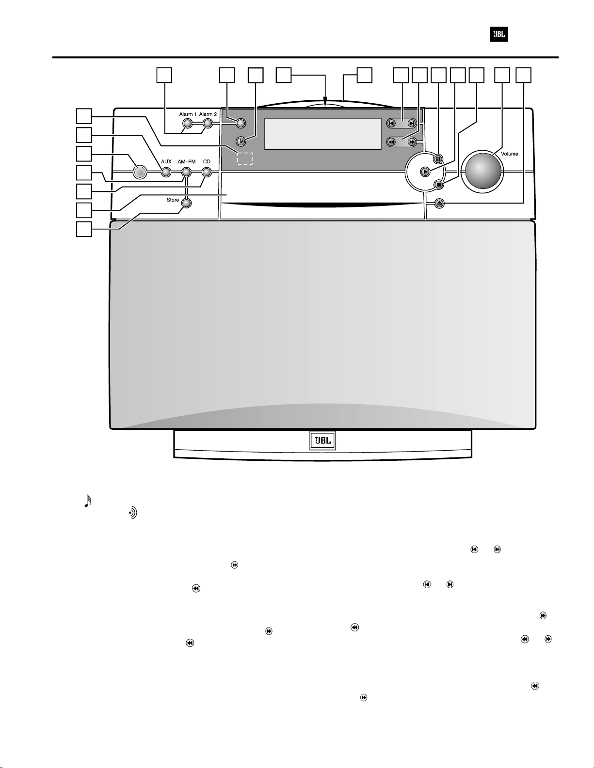
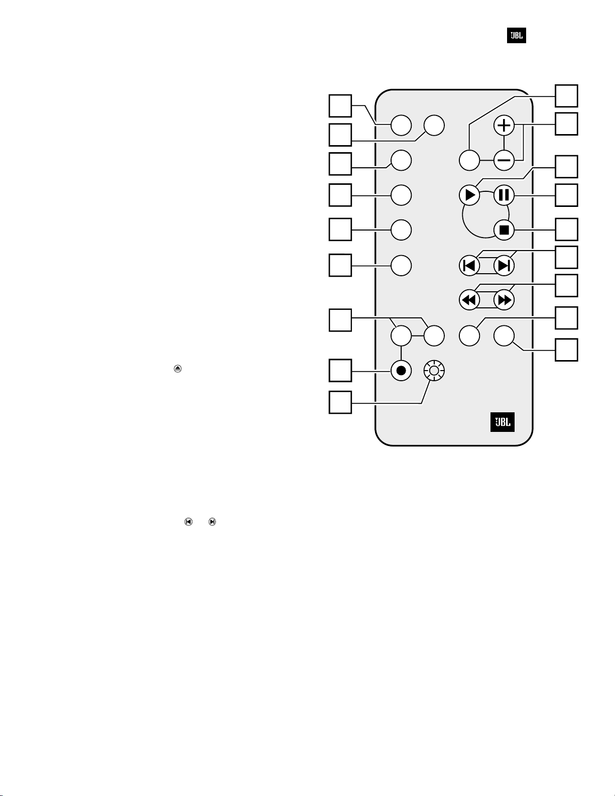
8. Pause - Press this button on the Harmony or remote
to cause the CD to pause.
9. Play - Press this button on the Harmony or remote to
cause the CD to begin playing.
10. Stop - Pressing this button will stop the CD playing.
11. Volume - To raise the volume turn the knob on the
Harmony clockwise or push “+” on the remote. To lower
the volume turn the knob counterclockwise or push “-” on
the remote.
12. Open - This button will open the CD holder tray
ejecting the CD.
13. IR Receiver - This is the area where the Infrared
Remote Receiver is located.
14. Auxiliary - Press this button to activate the auxiliary
audio input. This allows for the hookup of a cassette
deck, hi-fi VCR, CD changer, computer or another audio
source.
15. Power Indicator - This light indicates that the
Harmony is on when lit. To turn the Harmony on push
either “AUX”, “AM/FM”, “CD”, “PLAY” or “ALARM OFF” on
the Harmony or remote (or on the Harmony or
“Standby” on the remote).
16. AM/FM - This button allows the switching between
the AM and FM selection of the tuner.
17. CD Selector - Press this button on the Harmony or
remote to change to CD playing mode.
18. CD Door - this door opens allowing the CD tray to
slid out.
19. Store - Tune to the station that you wish to place in
memory. Push “Store” on the Harmony. To skip
between preset stations push or .
20. Display - Push this button to turn off the CD time
display or tuner display. When Harmony is off, pushing
this button will light up the clock display for five seconds.
21. Random Play - Push this button to play the tracks of
a CD in random order. The Harmony will automatically
delete each track it has played.
22. Repeat - Push Repeat to repeat the entire CD
playing. Push Repeat again to repeat a single track only.
The “Repeat” indicator will flash. Note: If “Random” and
“Repeat” are both engaged, the CD player will randomly
play the disc, deleting all played tracks, until the disc is
finished. It will then randomly play the disc again.
23. Mono - Pressing this button will play the selected
station without any stereo separation. There will be
much less background noise.
24. Sleep - This Button is used to turn the unit off
automatically after a selected amount of time in 10
minute increments up to 90 minutes. To turn off sleep
mode, push “Sleep” until “00” is indicated in the display.
25. Standby - Pressing this button on the remote will
cause the Harmony to turn on.
26. Mute - Press this button to lower volume completely
on the remote control, causing the power indicator to
flash. When “Mute” is pushed again, the volume will
return to its original level.
M
Mono
AM/FM
CD
Aux
12
StandbyStandby
AlarmAlarm Random
Random
Random Repeat
Repeat
Repeat
SnoozeSnooze
SleepSleep
VolumeVolume
20
23
24
25
21
22
17
16
14
1
5
6
7
8
9
11
26
10

Service Bulletin
Service Bulletin JBL9808 rev1 - January 2004 This is considered a Major repair
To: All JBL Service Centers
Model: Harmony AM/FM, CD Compact Sound system
Subject: Loss of all Control Functions or FM station Presets
In the event you receive a Harmony sound system for the complaint “all the controls stopped working”
or “the FM station presets disappear, even though I’ve never unplugged the unit”, perform the
following modification. This should also be performed as an upgrade if a unit is serviced for any
reason in the serial number range listed below:
1) To access & detach the CD assembly, obtain JBL Service Bulletin #JBL9804 (Harmony Disassembly
Procedure) and follow steps 1 −7.
2) Locate R264 and change from a 4.7kΩto a 2.2kΩSMD resistor −JBL part #QCF6A53-222.
3) Locate R286 and change from a 82kΩto a 68kΩSMD resistor −JBL part #QCF0851-683.
4) Continue with step 8 of the Harmony Disassembly Procedure to remove the CD assembly from the Main
PCB. It is not necessary to remove any cable connectors to perform the next step.
5) Locate Lithium Battery BT201 located at the edge of the Main PCB; replace with JBL part # FBE0030-
001. Battery with clips must be replaced on Main PCB.
6) Attach CD assembly back onto Main PCB, and replace assembly back into unit following all disassembly
instructions in reverse order.
7) Test unit by confirming all controls work and FM station presets hold their memory.
NOTE: The R286 silkscreen on the Main
PCB may be illegible or mismarked as
“R73S”.
Model Serial number
120V Serial number
230V Status Action
Harmony
AC0022-01001
to
AC0022-36021
AC0023-01001
to
AC0023-15720
Lithium battery
circuit failure
Change R264 from 4.7K to 2.2KΩ
Change R286 from 82K to 68KΩ
Replace battery BT201
Harmony
AC0022-36022
and above
AC0023-15721
and above Modified by factory NONE REQUIRED
8

HARMONY SERVICE BULLETIN JBL9809
Service Bulletin JBL9809 - September 1998 This is considered a Major repair
To: All JBL Service Centers
Model: Harmony AM/FM, CD Compact Sound system
Subject: Sleep Mode Display Brightness
In the event you receive a Harmony sound system with the complaint “the display is too dim in the Sleep mode”,
perform the following modification:
1) To access & detach the CD assembly, obtain JBL Service Bulletin #JBL9804 (Harmony Disassembly
Procedure) and follow steps 1 - 7.
2) Remove the volume control knob by pulling it straight off; remove the 7/16” mounting nut and washer.
3) To expose the Control PCB follow steps 1 - 5 only in the second section of the disassembly procedure.
4) Unplug the upper connector near the “Snooze” button to be able to separate the two chassis halves;
removing more connectors is not necessary.
5) Lay the unit’s front half face down on a padded surface.
6) Pry any beads of hot glue off and away from the 6 connecting tabs holding the Control board in place.
7) Remove the (3) silver-colored screws holding the control board to the unit.
8) Carefully pull the connecting tabs back one at a time; remove the Control board from the unit.
9) Turn board display-side up. Locate R281 and change from a 100Wtoa27Wresistor - JBL part# A091270.
10) Return Control board to unit and reconnect all tabs; follow all disassembly instructions in reverse order.
11) Observe brightness of the unit’s display in Sleep mode, and test all other functions.
Model Serial number
120V Status Action
Harmony AC0022-01001
to
AC0022-03195
Display too dim in Sleep Mode Replace R281 with 27W
resistor
Harmony AC0022-03196
and above Modified by factory NONE REQUIRED
9
CD Player/Tuner Stereo System HARMONY

HARMONY SERVICE BULLETIN JBL9904
Service Bulletin JBL9904 – October 1999 Warranty labor rate: MAJOR repair
To: All JBL Service Centers
Model: Harmony AM/FM, CD Compact Sound system
Subject: Weak FM Reception
In the event you receive a Harmony sound system with the complaint “poor FM stereo reception”, and FM
reception does not improve by using the larger dipole-type FM antenna supplied with the unit, check the rear of
the unit and see if there is a “LO/DX” switch. If there is no “LO/DX” switch, then the main PCB should be
replaced as per the instructions below:
Note: It is very important that the various screws do not get mixed up and inserted in other locations upon
reassembly. Make note, or label each removed screw set, and keep them apart from other screw sets.
1) Unplug all cables & connectors; place the unit on padded surface.
2) Carefully pry the speaker grille out of its recess and remove.
3) At the rear of the unit, remove the (4) screws holding the top cover on. Two are directly underneath the
handle and two are near the center of the unit.
4) Slide the top cover straight back and off the unit, exposing the CD mechanism.
5) At the front of the unit directly below the CD tray, remove the two CD mounting screws.
6) Pull the CD mechanism out and away from the unit. Looking at the rear of the unit, the right side will
pull away first and “pivot” around a thick wire cluster on the left side of the cabinet.
7) Unplug all connectors; make note of colors and locations - do not mix upon reassembly.
8) To separate CD assembly from Main PCB:
a) Remove the two lower, outermost screws from the small heatsink.
b) Remove the (4) silver-colored screws from the bottom of the PCB.
c) Remove the single screw from the RCA jack bracket.
d) Lift the CD mechanism off the PCB and carefully unplug the (4) remaining connectors.
9) Replace Main PCB with:
120v version - JBL part# APE0199-002, 230v version - JBL part# APE0199-001
Older version MAIN PCB Newer version MAIN PCB
Board has “LVM0199-001 REV B” Printed on it Board has “LVM0199-001 REV D” Printed on it
No external capacitors attached to PCB near IC201 2 external capacitors attached to PCB near IC201
Diode D231 is an axial part Diode D231 is a SMD part
10) Reattach main PCB to CD assembly and follow all disassembly instructions in reverse order until unit is
fully assembled.
11) Reattach either external FM antenna supplied with the unit. Plug in the power cord.
12) Test unit by pushing “AM/FM” button on Harmony or its remote control, then push the button for
one second and release for Harmony to begin tuner search for various stations.
13) Mark the bottom of the unit, under the base, with a bold black marker – “JBL9904”.
Model Serial Number 120V Serial Number 230V Status Action
Harmony
AC0022-01001
to
AC0022-13000*
AC0023-01001
to
AC0023-135000*
Weak FM reception
Replace Main PCB with
JBL part#
APE0199-02 (120V)
APE0199-001 (230V)
Harmony AC0022-13001* AC0023-135001*
and above New revision Main PCB NONE REQUIRED
* Versions of the Harmony Sound system with the “LO/DX” switch at the rear of the unit are the latest version, and need no
modification.
10
CD Player/Tuner Stereo System HARMONY

Service Bulletin
Service Bulletin JBL9905 Rev1 - December 2003 This is considered a Minor repair
To: All JBL Service Centers
Model: Harmony AM/FM, CD Compact Sound system
Subject: CD drawer not opening
In the event that you receive a Harmony speaker system with the complaint “CD drawer does not
open”, check the items listed below:
1) Replace the Motor Belt:
a)
At the rear of the unit, remove the (4) screws holding the top cover on. Two are directly underneath the
handle and two are near the center of the unit.
b) Slide the top cover straight back and off the unit, exposing the CD mechanism. Belt and motor should now
be exposed; replace belt with JBL part# BRW0002-001 *.
c) Replace cover and screws.
2) Make sure the top of the front grille is not interfering with the CD Drawer:
On some units, the bottom of the CD Drawer is so close to the top of the front grille it may brush against it
and impede the drawer’s movement. In this event:
a) Carefully pry the speaker grille out of its recess and remove.
b) The grille position can be lowered slightly by removing material from the six plastic grille pins with a
rotary tool, file, or similar tool.
c) Re-mount the grille; you may have to push the grille down slightly to create the needed gap
between the CD Drawer and the top of the grille.
3) Test unit by confirming original complaint not longer occurs.
* There were various versions of the CD mechanism ass’y; Motor Belt # BRW0002-001 should work for all versions.
The original CD mechanism had a motor pulley diameter of 0.53 in/13.4mm.
The later CD mechanisms had a motor pulley diameter of 0.81in/20.5mm.
White versions of the Harmony Sound system have the later version of CD Mechanism.
11

HARMONY SERVICE BULLETIN JBL9906
Service Bulletin JBL9906 - May 1999 This is considered a Major repair
To: All JBL Service Centers
Model: Harmony AM/FM, CD Compact Sound system (Gray only)
Subject: Noise when Playing CD’s
In the event that you receive a Harmony speaker system with the complaint “there is a mechanical noise
or ticking sound when playing Compact Discs, even when the volume is turned all the way down”, replace
the CD mechanism as per the instructions below:
Note: It is very important that the various screws do not get mixed up and inserted in other locations upon
reassembly. Make note, or label each removed screw set, and keep them apart from other screw sets.
REPLACEMENT OF CD MECHANISM
1) Unplug all cables & connectors; place the unit on padded surface.
2) Carefully pry the speaker grille out of its recess and remove.
3) At the rear of the unit, remove the (4) screws holding the top cover on. Two are directly underneath
the handle and two are near the center of the unit.
4) Slide the top cover straight back and off the unit, exposing the CD mechanism.
5) At the front of the unit, directly below the CD tray, remove the two CD mounting screws.
6) Pull the CD mechanism out and away from the unit. Looking at the rear of the unit, the right side will pull
away first and “pivot” around a thick wire cluster on the left side of the cabinet.
7) Unplug all connectors; make note of colors and locations - do not mix upon reassembly.
8) To separate CD assembly from Main PCB:
a) Remove the two lower, outermost screws from the small heatsink.
b) Remove the (4) silver-colored screws from the bottom of the PCB.
c) Remove the single screw from the RCA jack bracket.
d) Unplug remaining connectors.
9) Replace CD mechanism with replacement JBL part # AFA0086-001.*
10) Attach CD assembly back onto Main PCB, and replace assembly back into unit following all disassembly
instructions in reverse order. You must pry off the front plastic faceplate from the old CD mechanism
and replace it on the new unit.
11) Test unit by confirming all controls work and original complaint not longer occurs.
* The original CD mechanism has a motor pulley diameter of 0.53 in/13.4mm.
The new CD mechanism, part # AFA0086-001, has a motor pulley diameter of 0.81in/20.5mm.
(The motor pulley is located near the laser warning label)
Model Serial number
120V
Serial number
230V Status Action
Harmony
(Gray)
AC0022-01001
to
AC0022-22500**
AC0023-01001
to
AC0023-17384**
Mechanical noise or
ticking sound when
playing CD’s
Replace CD mechanism
with
JBL part #: AFA0086-001
Harmony
(Gray)
AC0022-22501**
and above
AC0023-17385**
and above
New revision CD
Mechanism NONE REQUIRED
** White versions of the Harmony Sound system have the latest version of CD Mechanism.
12
CD Player/Tuner Stereo System HARMONY

13
CD Player/Tuner Stereo System HARMONY
FM LOCAL/DISTANCE SWITCH
The Local/Distance Switch located above the antenna
connectors on the back of the Harmony is featured to
optimize the automatic tuning feature of Harmony's FM
Tuner to the listening environment where the unit is
operated.
If the unit is used in a metropolitan area with many
strong stations, the switch should be in LO (Local)
position. If it is not, slide it to LO position using a tip of a
pen. The Harmony should be able to automatically tune
to and bring in strong and listenable FM stations.
If the unit is used in a rural area with few weak or distant
stations, the switch should be in DX (Distance) position.
If it is not, slide it to DX position using a tip of a pen.
The Harmony should be able to automatically tune to
and bring in most listenable FM stations.
Harmony's ability to tune to more FM stations can be
further improved by using the included T-antenna,
mounting the T-antenna horizontally and high on a wall,
or using an external or cable FM antenna.
If a particular FM station that you would like to listen to
is still too weak to be tuned to automatically even with
the unit in DX mode, you may be able to tune to it
manually by repeatedly pressing and releasing the tune
( -or- ) buttons on the Harmony or on its remote, and
then pressing the “Mono” button on the remote (make
sure the word “Mono” is seen on the display). Keep in
mind that if the station is too weak, it may still be too
noisy to listen to.

55
44
33
22
11
A
A
B
B
C
C
D
D
E
E
F
F
G
G
AM/FM TUNER MODULE
PICK UP
UNIT
4558
LPF
KA9258D
SERVO MOTOR
DRIVER
CXA1782BQ
ASP
(RF AMP & SSP)
CXD2508AQ
DSP
IR REMOTE RECEIVER
LED BACK LIGHT
LCD DISPLAY
LCD DRIVER
LC75824E
DC
POWER
REGULATORS
CONTROL MICROPROCESSOR
ACI8747-012
TUNER AMP
+6V 8V 12V 12V
RDS DECODER
LC72720
EQ AND SPATIALISER
BUZZER
AUDIO INPUT SELECT AND VOLUME
TDA7313
KEY
(A/D KEY)
BA6218
TRAY MOTOR
POWER
OUTPUT
TDA7381
SUBWOOFER
SP
L/SP
R/SP
L
R
SUB
AUX
AM LOOP ANT
FM ANT
CD Player/Tuner Stereo System HARMONY
14

15
CD Player/Tuner Stereo System HARMONY
1
2
4
5
3
1 Battery Cover BPC0018-AM0 1
2 Battery 12 Volt FBH0120-001 1
3 Battery Wire VWP0002-001 1
4 Battery Bottom BPB0024-AM1 1
5 Screw T3.0xL10.0mm H101001-310 4
Ref
No. Description Part No. Qty
E
E
D
D
C
C
B
B
A
A
77
66
55
44
33
22
11
HARMONY BATTERY PARTS LIST


17
CD Player/Tuner Stereo System HARMONY
HARMONY MECHANICAL PARTS LIST
Ref. # Part Number Description Qty Ref. # Part Number Description Qty
1 AFA0079-001 Grill Assembly (Grey) 1
AFA0079-002 Grill Assembly (White)
2 AFA0081-001 Port Assembly 1
3 AFA0081-001 CD Loader 1
4 APE0199-002 Main PCB Assembly (120V) 1
APE0199-001 Main PCB Assembly (230V)
5 APE0200-002 Control PCB Assembly 1
6 APE0231-001 Power PCB Assembly 1
7 BPT0024-001 Filter 1
8 BNP0043-001 PVC Plate, Display Sheet 1
9 BPA0026-AM1 Bottom Cover 1
10 BPA0027-AM1 Rear Cover 1
11 BPB0016-AMO Back Cabinet (Grey) 1
BPB0016-BBO Back Cabinet (White)
12 BPB0018-AM1 Handle Cover (Grey) 1
BPB0018-BB1 Handle Cover (White)
13 APE0200-031 Snooze/Alarm Control PCB Assy 1
14 GAL0091-001 Heat Sink 1
15 BPC0019-001 Wire Cover 2
16 BPD1020-AM0 CD Door (Grey) 1
BPD1020-BB0 CD Door (White)
17 BPF0023-AM1 Front Cabinet (Grey) 1
BFP0023-BB0 Front Cabinet (White)
18 BPH0030-Z01 Screw Holder (Left) 1
19 BPH0036-001 Screw Holder (Right) 1
20 BPH0035-001 PCB Holder 1
21 BPK1038-AN0 Alarm Knob (Grey) 1
BPK1038-BC0 Alarm Knob (White)
22 BPK1052-001 Function Knob (Left) 1
23 BPK1053-001 Function Knob (Right) 1
24 BPK5039-AM0 Volume Knob (Grey) 1
BPK5039-BB0 Volume Knob (White)
25 BPN0063-001 Display Window (Grey) 1
BPN0063-002 Display Window (White)
26 BPN0064-000 LED Lens (Grey) 1
BPN0064-001 LED Lens (White)
27 BRB0006-001 Grill Retainers (Grey) 6
BRB0006-002 Grill Retainers (White)
28 RBR0007-001 Rubber Foot (Grey) 8
BRB0007-002 Rubber Foot (White)
29 BRB0012-001 Plugger 1
30 BRB0013-001 Socket Rubber 1
31 CLJ0010-001 Logo Plate 1
32 DSU0020-001 Spring 2
33 FPZ0024-001 Buzzer 1
34 FTT1030-311 3" Midrange Driver 2
35 FTW2040-311 4" Woofer 1
36 GAL0100-001 Heat Sink 1
37 GF10012-001 Fiber Washer 2
38 GSE0179-001 Transformer Bracket 1
39 GSE0185-Z01 X’former Bracket 1
40 GSE0186-001 Socket Bracket 1
41 GTN0037-001 Tuner Cover (A) 1
42 GTN0038-001 Tuner Cover (B) 1
43 IVE0075-002 3" Speaker Sponge 2
44 IVE0076-006 4" Speaker Sponge 1
45 IVE0081-001 Rubber Sponge (Left) 1
46 IVE0082-001 Rubber Spponge (Right) 1
47 BPG1027-001 GearD 2
48 BPG1039-001 Gear Rail 1
49 BPG1041-002 Gear Top 1
50 BPH0027-001 Gear Holder 1
51 DSF0007-001 Shaft (A) 1
52 DSF0008-001 Shaft (B) 1
53 GSE0173-001 Motor Bracket 1
54 FMD0004-001 Motor DC 4V 1
55 TTN1204-001 Power Transformer (120v) 1
TTN2304-001 Power Transformer (230v) 1
56 BPG1038-001 Gear Guide 1
57 BPH0029-Z03 CD Mechanism Holder 1
58 BPH003I 001 Rail Holder (Right) 1
59 BPH0032-001 Rail Holder (Left) 1
60 BPH0033-001 Turntable Holder (Left) 1
61 BPH0034-001 Turntable Holder (Right) 1
62 BPP0006-001 Pulley 4
63 BPP0007-001 Motor Pulley 1
64 BPT0012-AMO Turntable 1
65 BRF0025-001 Cushion (A) 1
66 BRF0026-001 Cushion (B) 1
67 BRF0027-001 Cushion (C) 1
68 BRW0002-001 Motor Belt 1

18
CD Player/Tuner Stereo System HARMONY
Ref. # Part Number Description Qty Ref. # Part Number Description Qty
69 DTB0800-034 Tubing 1
70 GSE0172-001 CD Base Holder Bracket 1
71 MSV0002-001 Lever Switch 2
72 GTN0033-001 Heat Sink 1
73 GAL0074-002 Heat Sink (A) 1
74 GAL0087-002 Heat Sink (B) 1
75 APE0201-021 CD Connector PCB Assembly 1
76 APE0020-042(120v) AC-DC Power PCB Assembly 1
APE0200-041(230v)
77 IVE0084-001 Sponge 1
78 IVM0001-003 Acoustic (To Port) 1
S1 H016502-316 Screw W6#20xL16.0mm 2
Washer head
S2 H060308-112 M3.0x0.5PxL12.0 mm Flat Head 2
S3 H101001-106 Screw T3.0xL6.0 mm 5
S4 H101001-108 Screw T3.0x1.27P-2RHxL8.0 mm 7
S5 H101001-310 Screw T3.0xL10.0 mm 21
S6 H101001-312 Screw T3.0xL12.0 mm 16
S7 HI 01002-312 Screw T3.0xL12.0 mm W/Washer 4
S8 H101012-312 Screw T3.0x1.27PxL12.0 mm 12
Round Head
S9 H101501-106 Screw T2.6xL6.0 mm 2
S10 H106401-105 Screw T2.0x0.635PxL5.0 mm 2
S11 H120301-110 Screw M3.0x0.5PxL10.0 mm 5
S12 H120301-312 Screw M3.0x0.5PxL12.0 mm 2
W/Washer
S13 H060201-116 Screw M2.6x0.45PxL16.0 mm 2
S14 H060001-108 Screw M1.7xL8.0 mm 2
S15 H060101-304 Screw M2.0x0.4PxL4.0 mm 2
S16 H101001-320 Screw T3.0x1.27PxL20.0 mm 1
S17 H101502-205 Screw T2.6x1.058PxL5.0 mm 4
Washer Head
S18 H120301-106 Screw T3.0xL6.0 mm 4
S19 H120301-306 Screw M3.0x0.5PxL6.0 mm 3
S20 H120301-308 Screw M3.0x0.5PxL8.0 mm 2
W1 HWC4016-302 Washer OD4.0xID1.6xTO.2mm 2
Mylar
S21 H100301-106 Screw T3.0xL6.0 mm 2
4999A-376 CON/WIRE 2 COND 420 mm 1
P=2.5 mm UL2468 22 GA
MAIN PCB CN502 TO R SPK
4999A-377 CON/WIRE 2 COND 240 mm 1
P=2.5 mm UL2468 22 GA
POWER PCB CN503 TO
SUBWOOFER SPK
4999A-378 CON/WIRE 4 COND 220 mm 1
P=2.5mm UL2468 22 GA
POWER PCB CN503A TO
MAIN PCB CN503B
4999A-393 CON/WIRE 4 COND 500 mm 1
UL1007 22 AWG POWER PCB
CN903A TO MAIN PCB CN903B
4999A-394 CON/WIRE 10 COND 500 mm 1
UL2877/2468 26AWG
APE0200-021 R-ENCODER
APE0200-031 ALARM ASSY
APE0200-042 POWER ASSY
APE0199-002 (120V) MAIN PCB ASSY
APE0199-001 (230V) MAIN PCB ASSY
AFA0086-001 COMPLETE CD MECHANISM ASSY
CD Assy
AFA0053-002 GEAR ASSY 1
APE0199-002 MAIN ASSY MAIN PCB AY 1
W/O RDS (UL)
BPG1038-001 GEAR GUIDE TO CD LOADER-1 1
BPH0029EZ04 CD HOLDER MECHANICAL 1
HARMONY (WHITE)
BPH0031-001 HOLDER RAIL HOLDER (R) 1
BPH0032-001 HOLDER RAIL HOLDER (L) 1
CD LOADER
BPH0033-002 HOLDER TURNTABLE (L) 1
BPH0034-001 HOLDER TURNTABLE (R) 1
BPP0006-001 PULLEY TO MOTOR 4
BPP0007-002 PULLEY MOTOR (ABS + PA) 1
CD ASSY
BPT0012CBB0 TURNTABLE PEARL WHITE (M2) 1
SHARP RADIO (JBL)
BRF0034-001 CUSHION SANYO IEA2443A08103 1
RUBBER (A)
BRF0035-001 CUSHION SANYO IEA2443A08102 2
RUBBER (B)
BRW0002-001 MOTOR BELT D=39.7 1
CD BASE HOLDER
FMD0004-001 MOTOR (SHAFT 37.00mm) 1
GSE0172-001 BRACKET CD BASE HOLDER 1
GSE0173-001 BRACKET MOTOR BRACKET 1
LEVER SW
Other manuals for HARMONY
3
Table of contents
Other JBL Media Converter manuals
Popular Media Converter manuals by other brands

Maximum Controls
Maximum Controls MAX WIEGAND Quick installation guide

Pro-Ject Audio Systems
Pro-Ject Audio Systems Stream Box S2 Instructions for use

Renishaw
Renishaw FORTiS-S FS installation guide

Fermax
Fermax DUOX PLUS quick start guide

HeadRoom
HeadRoom Micro DAC owner's manual

Tyba
Tyba Muse quick start guide