Uhlenbrock Elektronik 74 400 User manual

Loco-Decoder 74 400
Digital decoder for dc-motors
for DCC-format
Suitable for dc-locos by Bemo, Brawa (Life-Like), Fleischmann, Gützold, Lili ut, Lima, Piko,
Märklin-Hamo, Rivarossi (Atlas), Roco, Trix. Not suited for coreless instrument motors!
Specifications
These are s ecifications of the loco-decoder 74 400:
can drive all dc motors (excluding coreless motors)
can be used on all DCC-conforming layouts
short (1-127) as well as long (128-9999) address
14, 27, 28 and 128 s eed levels
automatic conversion to analog o eration
su orts all rogramming algorithms defined by the NMRA
NMRA/DCC conformant
2 direction de endent function out uts, to be controlled through one of these keys of the
Command Station: function and off, FL, F0, light
shunting s eed (half s eed) can be enabled through function F3
acceleration and deceleration delay can be turned off or on through function F4
acce ts the DCC brake signal generated by some DCC brake units
(like, e.g., the Uhlenbrock Power-3 Booster)
Analog mode fuatures
The decoder can be used with an analog throttle on an analog layout. The dc ower su ly is
automatically recognised by the decoder as long as Bit #2 of CV #29 is set to the value 1.
In analog mode the two function out uts are always on and they change according to the loco
driving direction (track olarity).
Technical Data
Max. motor current: 0.8 am
Motor eak current: 2.0 am s
Auxiliary out uts: 2 x 0.9 am
Total load: 0.9 am
Size: 19 x 16 x 5 mm (3/4" x 5/8" x 3/16")
Address range: 1- 9999
The decoder is factory reset to address 3, 14 s eed ste s and automatic recognition of a dc
ower su ly.

A short circuit from motor brushes or ancillary outputs
to pickup shoes, frame, or wheels may destroy the device!
Installation of the loco-decoder 74400
Motor connections
Connect the red wire to the loco current
icku which - when the loco is sitting on
the rails - is in electrical contact with the
right rail (right as judged by the engineers
view: looking from inside the loco towards
the loco front). Connect the black wire to
the current icku which is in electrical
contact with the left rail. Connect the oran-
ge and the gray wire to the two brushes of
the motor: the orange wire should go to the
brush which, rior to decoder installation,
was in contact with the right rail. The other
brush (the left one) should be connected
to the black wire.
Important: After installing the decoder all connections between rails and motor must be removed.
The motor must only be connected to the decoder gray and orange wires. RF interference
su ressors and ca acitors should be retained.
Installation of an extra function
Connect the white and yellow leads to the front and rear lam s. The lam s return (common wire)
must be connected to the blue lead. Should either the driving direction or the directional lighting
come on wrong, then lease swa , res ., the orange and gray leads on the motor or the white
and yellow wires feeding the lam s. If both the driving direction as well as the lights are wrong-
meaning that they agree with each other but they do not agree with what is shown to be forward
on the Command Station - then one can sim ly change the value of Bit #0 of CV #29 (without having
to resort to de/soldering).
Connect the white and yellow wires to each other if you wish them to work direction-inde endent
- that is, if you wish for the lights to always stay on inde endently of the loco driving direction.
The yellow and white wires can also be used to control other devices, e. g. a smoke generator.
Caution
Please take care to substitute any 12 V lam with a 19 V one - or else lam s wont last long.
Fixing the unit in the model
Use the su lied adhesive ad for fixing the decoder in lace within the loco. The ad kee s the
unit insulated and fixed at its osition.
In case the loco has a high current consum tion, we recommend to fasten the decoder directly
to the loco metallic frame using hot glue - all common brands are suitable for this. Please be
careful not to make any electrical contact between the loco frame and the decoder!
afety first
Check for ro er wiring after installation using a wiring checker or an ohmmmeter. Make sure
that the shell will not touch the unit and that no wires can be caught ( ulled, cut) when loco
shell is laced back again on the loco frame.
black
Motor
orange
red
DCC
loco-decoder
white
blue
yellow
gray
driving direction
Connection 74400

Programming Uhlenbrock DCC decoders
Uhlenbrock DCC decoders can be rogrammed with every DCC Command Station featuring
Register, CV (direct) or aged rogramming.
Programming DCC decoders with the Intellibox
The Intellibox features an easy to use menu for rogramming DCC decoders. This menu also
su orts the rogramming of long addresses without having to erform com licated com utations
by hand. In fact, one can directly ty e a long address and have the Intellibox automatically
erform the com utations needed in order to find out what values to write into CV #17 and CV
#18. The Intellibox shall also write those values into CV #17 and CV #18, as well as enabling long
addresses by setting Bit #5 of CV #29. Please refer to the corres onding cha ter of the Intellibox
manual for more information on this oint.
How to compute the value to be programmed into CV #29 (Register #5)
CV #29 (Register #5) is used to configure the decoder. One can for exam le invert the loco driving
direction (as well as its directional lights) or change the number of s eed ste s. It is ossible
to configure the decoder for digital-only o eration or for mixed (and automatic) analog/digital
o eration. Finally, one can tell the decoder to react to commands sent to either the short address
(CV #1) or to the long address (CV #17/18).
You can use the Value column of the following table in order to com ute by summation the value
to be written into CV #29 (or Register #5) in order to obtain the desired decoder configuration.
Example (if not using Bit programming):
Normal driving direction value =0
14 s eed ste s value =0
autom. analog/digital value =4
short adress value =0
The sum of all of these values gives 4.
This is the value to rogram into CV #29 (or
Register #5) - and, this value ha ens also to be
the factory default value for CV #29.
Function
Normal driving direction
opposite driving direction
14 / 27 speed levels
28 / 128 speed levels
Digital mode only
Automatic analog or digital operation
Short address (C #1, Register #1)
Long address (C #17 und C #18)
Value
0
1
0
2
0
4
0
32
BIT
0
1
2
5
Programming a long address without using a menu
If you have to rogram the decoder for o eration on a long address and you are not using a
Command Station which makes this rocess automatically, then you have to com ute what value
to write into CV #17 and CV #18. Well now show by exam le what to do using long address 2000.
Divide the choosen long address by 256 (here 2000/256 = 7 with a remainder of 208).
Take the integer quotient of that division (7 in our exam le) and add 192 to it.
Write the result of this addition (7+192 = 199) into CV #17.
Write the remainder of the division (208 in our exam le) into CV #18.
Important: make sure that Bit #5 of CV #29 is set to 1, so as to tell the decoder to react to
commands sent to its long address (CV #17/18) and not to commands sent to its short address.
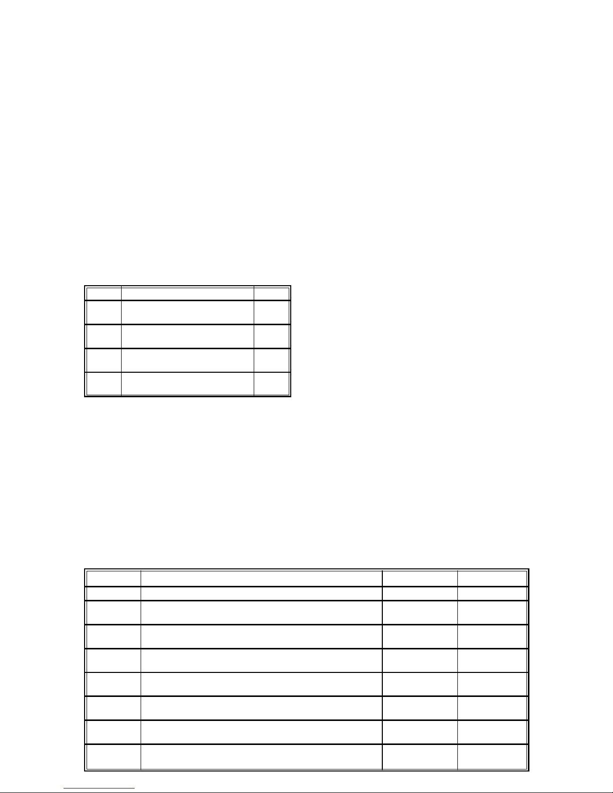
Register Table
Description
Decoder (short) address
Minimum speed
at speedstep 2
Acceleration delay
1 = no delay, 255 = max. delay
Deceleration delay
1 = no delay, 255 = max. delay
Decoder configuration
Check chapter on decoder configuration/CV #29
Page Register
Used during paged programming
Maximum speed
at highest speedstep
Manufacturer id
for Uhlenbrock Elektronik GmbH
Register-Nr.
1
2
3
4
5
6
7
8
Allowed range
1-127
1-31
1-255
1-255
see C 29
-
1-95
-
Value
3
5
2
2
4
-
90
85

Uhlenbrock lektronik GmbH
Mercatorstr.6
D-46244 Bottrop
Made in Germany
Unsere Pluspunkte für Sie:
Jahre Garantie ab Kaufdatum
auf alle unsere Produkte.
Service
Bei einem eventuellen Defekt senden Sie bitte den Baustein
zusammen mit dem Kaufbeleg und einer kurzen Fehlerbeschreibung
unter Angabe der Decoderadresse zur Reparatur an uns zur ck.
Hotline
Wenn Sie Fragen haben, wir sind f r Sie da!
Ihr direkter Weg zum Techniker: 0 0 45 - 85 83 7
Mo - Di - Do - Fr von 14 bis 16 Uhr und Mi von 16 bis 18 Uhr
CV
1
2
3
4
5
6
7
8
17/18
29
Value
3
5
2
2
90
-
1
85
199
208
4
CV Table (Configuration Variables)
Description
Decoder short address
Minimum speed
Acceleration delay
1 = no delay, 255 = max. delay
Deceleration delay
1 = no delay, 255 = max. delay
Maximum speed
Not used
Decoder/software version number
Manufacturer id
for Uhlenbrock Elektronik GmbH
Long address
C 17 high byte (with top 2 bits = 1), C 18 low byte
Bit #5 of C #29 tells whether the short (0) or the long (1) address is
active.
Decoder configuration (see chapter on decoder configuration)
Allowed range
1-127
1-31
1-255
1-255
1-95
-
-
-
-
-
0-255
Important
If a decoder does not react to drive/function commands after a rogramming o eration, then it
is most robable that its address has been modified. Please read CV #1 in order to find out what
the (short) address is - of course, had the long address (CV #17/18) been enabled (by setting
Bit #5 of CV #29) then also those CVs should be ins ected, either directly or, in case of the
Intellibox and Fleischmann TwinCenter, by using the long address menu.
www.uhlenbrock.de
Be it most recent information about Intellibox, a ricelist or a listing of authorized dealers, lus
various ublications to download, our website warrants your visit in every case.
Warranty Statement
Every item is fully tested for functioning before shi ment. If a defect occurs within two years
after urchase, the item will be re aired free of charge against resentation of urchase roof.
Damages caused by overload or im ro er treatment are not covered by this warranty.
For EU only
Please note that decoders may only used in models carrying the EC conformance label.
Item no. 74 40 09.02 Be
Table of contents
Other Uhlenbrock Elektronik Media Converter manuals

Uhlenbrock Elektronik
Uhlenbrock Elektronik 76 500 User manual

Uhlenbrock Elektronik
Uhlenbrock Elektronik 75900 User manual

Uhlenbrock Elektronik
Uhlenbrock Elektronik 75 100 User manual

Uhlenbrock Elektronik
Uhlenbrock Elektronik 75200 User manual

Uhlenbrock Elektronik
Uhlenbrock Elektronik 67810 User manual

Uhlenbrock Elektronik
Uhlenbrock Elektronik 73 510 User manual

Uhlenbrock Elektronik
Uhlenbrock Elektronik 76 500 User manual