Digitools DigiSound-4.1 User manual

1
User Manual
DigiSound-4.1, -4.2, -4.3, -3.4, -3.5, -3.6
DigiSound-5.1, -5.2, -5.3, -5.5, -5.6
Document version: 20210827
Decoder software version (CV7 value): 037 or higher

2
Content
KEY FEATURES: ........................................................................................................................................ 4
MAIN PARAMETERS: ................................................................................................................................ 6
INSTALLING THE DECODER: ....................................................................................................................... 8
DigiSound-x.1: ................................................................................................................................. 8
DigiSound-x.2: ................................................................................................................................. 9
DigiSound-x.3: ............................................................................................................................... 10
DigiSound-x.4: ............................................................................................................................... 11
DigiSound-x.5 and DigiSound-x.6: ................................................................................................ 12
INSTALLATION: ...................................................................................................................................... 15
MOTOR CONTROL INTERFACE: ................................................................................................................. 15
Setting the load control: ............................................................................................................... 15
SETTING THE SPEED OF THE LOCOMOTIVE: ................................................................................................. 17
3-point speed curve (CV29,4=0): .................................................................................................. 16
28-point speed curve (CV29,4=1): ................................................................................................ 16
Speed set point multiplier: ........................................................................................................... 17
Setting acceleration and deceleration: ........................................................................................ 19
FUNCTION OUTPUTS: ............................................................................................................................. 19
Function output registers: ............................................................................................................ 22
OTHER FUNCTIONS: ............................................................................................................................... 29
Shunting mode: ............................................................................................................................ 29
Disabling acceleration and deceleration: ..................................................................................... 29
Lowering brightness: .................................................................................................................... 29
Locomotive Driver mode: ............................................................................................................. 29
Analogue mode: ........................................................................................................................... 32
Operation on track controlled by break dynamo: ........................................................................ 32
ABC mode: .................................................................................................................................... 33
RailCom: ........................................................................................................................................ 35
Multi locomotive operation (consist mode): ................................................................................ 37
Disconnecting function: ................................................................................................................ 39
SUSI interface: .............................................................................................................................. 41
Saving function button status: ..................................................................................................... 41
Heavy vehicle function: ................................................................................................................ 42
Energy supply (DigiCap, DigiPack): ............................................................................................... 43

3
SOUND SETTINGS: .................................................................................................................................. 46
Volume settings ............................................................................................................................ 45
Setting volume of different sounds .............................................................................................. 45
16-bit sounds ................................................................................................................................ 48
Delaying acceleration ................................................................................................................... 48
Steam locomotive mode .............................................................................................................. 46
Synchronous sign input ................................................................................................................ 47
Multichannel steam locomotive sound ........................................................................................ 49
Randomly starting sounds ............................................................................................................ 48
Lowering volume .......................................................................................................................... 49
Running in neutral gear ................................................................................................................ 50
Muting function: ........................................................................................................................... 53
Daisabling sound controlled acceleration: ................................................................................... 53
PROGRAMMING: ................................................................................................................................... 54
ACK impulse: ................................................................................................................................. 54
Resetting CV registers to default and saving: ............................................................................... 54
Counting long address: ................................................................................................................. 52
Default settings of function buttons: ........................................................................................... 63
Configuration registers CV29, CV49: ............................................................................................ 54
CV REGISTERS: ...................................................................................................................................... 55

4
Thank you for choosing the product developed and produced by the
Hungarian DigiTools Electronics Ltd.
Key features:
The main purpose of this user manual is to introduce the operation and settings of the
DigiSound-4.x and DigiSound-5.x combined locomotive decoder. The serial no. 4 and 5
sound decoders are the same in terms of functions and settings, they only differ in the
size of the sound storing memory.
Hardware changes of DigiSound-x.x decoders compared to serial 3:
- The capacity of the built-in capacitors have been doubled to diminish the risk of
contact problems.
- DigiSound-x.1 (8-pin NEM652) decoder has 2 additional function outputs.
- The height of the DigiSound-x.1 decoder has been decreased: 11.2 * 24.0 * 3.2 mm.
- The size of the DigiSound-x.5 decoder has been significantly reduced (PluX22):
15.1 * 25.4 * 4 mm.
- The DigiSound-x.5 decoder has got 7 pcs. of function outputs on top of the 2 light-
ing outputs. The TTL GPIO points of the PluX22 interface, can be the CV register’s
programmable output and input (AUX8 - AUX10).
- The DigiSound-x.5 decoder has got SUSI interface for communicating with external
devices (dynamic smoke, Brawa Traxx lighting, evaluating the position).
- Preparation of our newly emerging DigiPack2 energy storing device.
- The DigiSound-4.x 64Mbit (8MB) audio memory can store 3-6 mins of audio de-
pending on the resolution.
- The DigiSound-5.x 128Mbit (16MB) audio memory can store 6-12 mins of audio
depending on the resolution.
The length of the stored audio depends on the resolution of the sounds.

5
Changes in version v35-36 software:
- Handling trigger sign separately as a chanel, correcting “csi-hu” timing.
- Correcting sound sample loop chacking in trigger mode.
- Setting P element overflow issue.
- Setting Aux5-10 interfaces PWM 100% filling issues.
Changes in v37 software:
- Setting Hm_out_false condition issue.
- Setting Trigger sign at start issue.
- Expanding the function of „phase” bit in function outputs.
- „Wheel sparks”, neon1, neon2, impulse mode at function interfaces.

6
-
Main parameters:
o Communication by NMRA DCC standard
o 28, 128 speed rates, programmable speed graph
o Address range 1-9999
o Maximum 1 A engine output
o Load control (can be enabled/disabled via the CV register)
o 20 kHz motor PWM frequency
o 2+4 (NEM652) or 2+4 (21MTC) 2+7+3 (PLUX) pcs. short circuit protected func-
tion interface
o Analogue mode
o Asymmetric DCC sign perception (ABC mode)
o Permanent break distance in ABC mode
o RailCom
o Consist (multi-locomotive) operation
o FL, F1-F28 function handling
o Adjustable light intensity
o Shunting mode
o Acceleration, deceleration modes can be switched on and off
o Locomotive driver function
o Disconnecting function
o 3 or 28-point adjustable speed graph
o Different interfaces for the different standards
o Sound playing features:
o 4 - 8Ω speaker output
o D class sound terminal stage, 2,7Watt performance on 4 Ω
o 8 or 16 bit resolution, 22,05kHz sampling frequency
o 8 independent soundtracks played at the same time
o The speaker output is not short circuit protected!

7
Installing the Decoder:
Before installing the decoder it is reccommened to do as follows:
o if you are digitalizing your existing analogue system check if there is an inte-
grated buffer capacitor remained on the rail!
o when digitalizing old, not prepared locomotives it is essential to check if the
value of the buffering capacitor is not higher than 47nF. If there is no reactor
coil between the motor and the decoder, do not leave the capacitor on the
output of the motor. Remove any capacitor between the two motor leads and
the frame,
o clean all the current collector skates and the wheels of the locomotive,
o run the motor starting from ~5-10V in neutral gear, while measuring the cur-
rent consumption. If it takes more than 200mA, check the state of the motor
brush and the commutator and if necessary sweep out the coal powder from
the gaps between the bites,
o check the light bulbs, if necessary change them into higher voltage ones. The
new bulbs should have at least 16V,
o check the insulations. In case of locomotives, where one of the poles of the
rail is the metal body itself it is important to check if the motor’s insulation is
adequate,
o check the condition of the engine in terms of running and lubrication.

8
DigiSound-x.1:
The outputs of the decoder have the standard NEM652 interface.
When attaching the decoder be careful to link the orange output of the interface to pin 1
on the printed circuit, which is usually indicated with an asterisk.
In the event of an incorrect attachment, no damage is done, but the locomotive will go in
the opposite direction and the lighting function will not work.
The standard length of the cable is 8 cm, but different cable lengths are available for indi-
vidual orders.
DigiSound-x.1 decoder with the new interface
Sizes: 11.2 mm x 24.0 mm x 3.2 mm

9
DigiSound-x.2:
The outputs of the decoder have the standard 6-pole NEM651 interface.
It is available in two different sizes:
straight interface
90° interface
DigiSound-5.2 with 90° interface
In the event of an incorrect attachment, no damage is done, but the locomotive will not
work. In this case connect the device the opposite way around.
Sizes: 11.2 mm x 24.0 mm x 3.2 mm
10
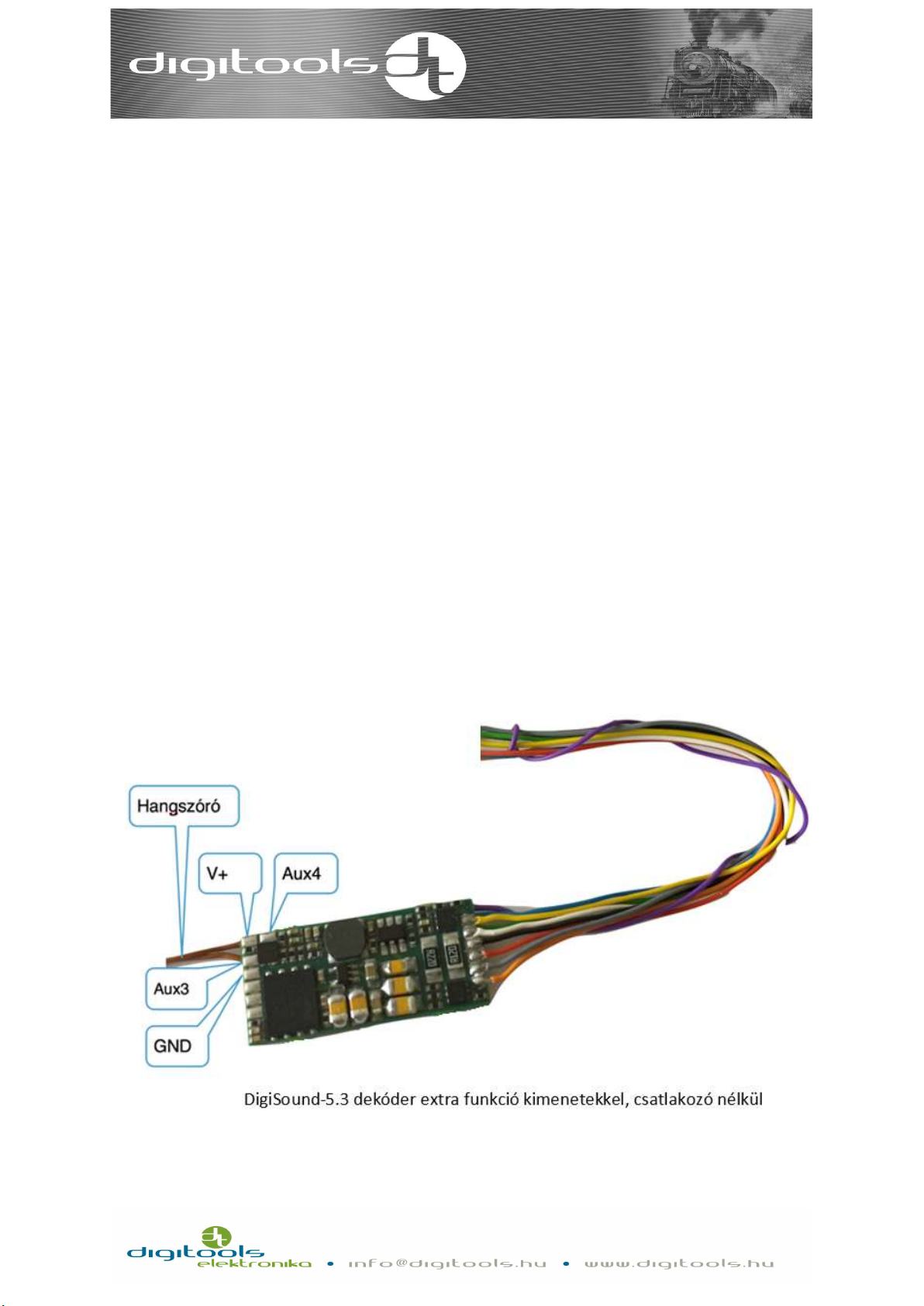
DigiSound-x.3:
The outputs of the decoder are being shipped with customized length of cables, without
interface.
Let us know what length you need when placing the order.
This type is ideal for digitalizing old models which do not have printed circuit for motor.
The list below will help you attach the unit:
o Orange: Right motor terminal
o Yellow: Rear light
o Green: AUX1 function output
o Red: Right track connection
o Grey: Left motor terminal
o White: Headlight
o Blue: Function interface. Common „+” pole
o Black: Left track connection
o Purple: AUX2 function output

11
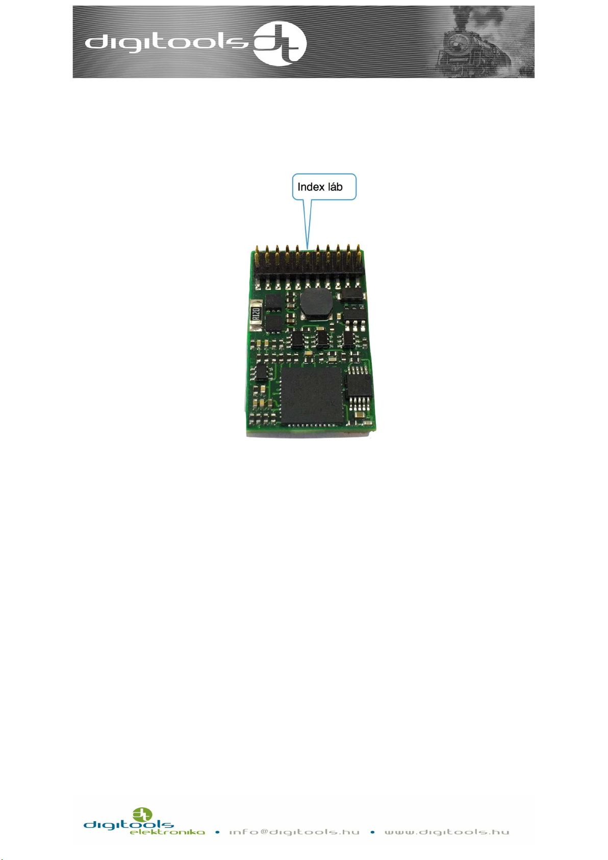
DigiSound-x.4:
The outputs of the decoder have standard MTC 21 pole interface.
DigiSound-5.4 21 with MTC interface
The point indicated in the picture is the „index” pin. The „index” pin is responsible for the
positioning of the decoder. This pin is omitted on the preparatory panel in the locomo-
tive.
An incorrect attachment may result in damage in the decoder!
The loudspeaker output on the decoder is led out from the socket, so the loudspeaker
must be connected to the endpoints on the locomotive’s preparatory panel. For instruc-
tions about the installation refer to the user manual.
Speaker terminals are marked with S + S-, SP + SP- on the preparatory panel. (e.g.: Roco
PluX22 Taurus: SPK, Piko Szergej: LSA and LSB, JC Taurus: SP1, Piko A26: LS+ and LS-)
Sizes: 15.0 mm x 31.0 mm x 4.0 mm
Index láb
12
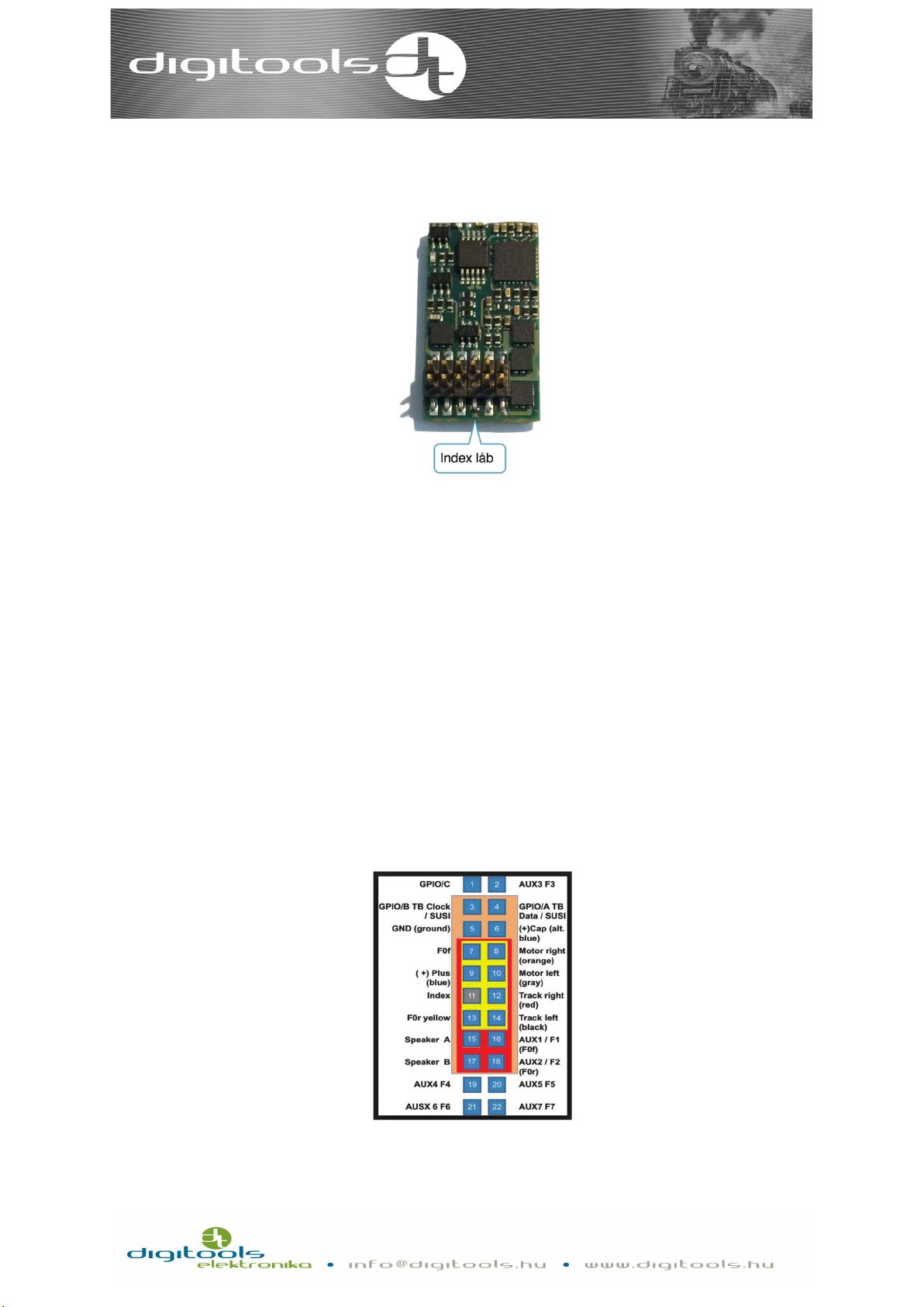
DigiSound-x.5 and DigiSound-x.6:
The outputs of the DigiSound-x.5 decoder have standard NEM 658, PLUX22 interface.
The outputs of the DigiSound-x.6 decoder have standard NEM 658, PLUX16 interface.
DigiSound-5.5 with PLUX22 interface
The missing pin in the middle of the pin line is the „index” pin. On the preparatory panel
of the locomotive, the holes for this pin are omitted or marked separately.
An incorrect attachment may result in damage in the decoder!
The loudspeaker output on the decoder is led out from the socket, so the loudspeaker
must be connected to the endpoints on the locomotive’s preparatory panel. For instruc-
tions about the installation refer to the user manual.
Speaker terminals are marked with S + S-, SP + SP- on the preparatory panel.
Sizes: 15.0 mm x 31.0 mm x 4.0 mm
13
DigiSound-x.7:
The interfaces of the decoder have got standard NEM 658 with PLUX12 interface.
DigiSound-5.7 with PLUX12 interface
The missing pin in the middle of the pin line is the „index” pin. On the preparatory panel
of the locomotive, the holes for this pin are omitted or marked separately. The loud-
speaker output on the decoder is led out from the socket, so the loudspeaker must be
connected to the endpoints on the locomotive’s preparatory panel. For instructions
about the installation refer to the user manual. Speaker terminals are marked with S + S-,
SP + SP- on the preparatory panel.
The PluX12, PluX16, PluX22 decoders are compatible with each other.
A decoder with the less no. of pins can be connected to a panel with more pins taking in-
to consideration the place of the index pin and as a result the functions of the pins left
out will not work.
Cable order of PluX decoders
Sizes: 11.0 mm x 20.0 mm x 3.0 mm

14
DigiSound-5.8:
DigiSound-5.8 with NEXT18-S interface
The interfaces of the decoder have got standard NEM 668 with Next18-S interfaces.
In the event of an incorrect attachment, no damage is done, but the locomotive will go in
the opposite direction and the function interfaces can be mixed. In this case attach the
device on the different direction. The loudspeaker output on the decoder is led out from
the socket, so the loudspeaker must be connected to the endpoints on the locomotive’s
preparatory panel. For instructions about the installation refer to the user manual.
Sizez: 11.0 mm x 22.0 mm x 3.6 mm

15
Installation:
After having installed the decoder, check the position of the cables, they should not be in
the way of any moving or rotating part. Pay particular attention to the cable of the loud-
speaker, twist the two blades and make sure they do not touch anything electronically. If
everything is fine, you may start the voltage test.
Motor control interface:
The decoder can control one permanent magnetic commutator direct current motor.
The H bridge made of FET transistors continuously has maximum 1A current.
The load control frequency is 20kHz.
The output is short circuit protected.
The protection is guaranteed only in case of standard installation!
If during assembling or because of an incorrect installation a short circuit should occur,
for example, if one of the cables of the motor output (grey, orange) and the rail cables
(black, red) touch, this may result in damage in the decoder.
If the short circuit protection sign alarms the decoder can only be reinstalled after the iso-
lation of voltage.
Setting the load control:
The CV registers shown in the following chart belong to the motor speed control:
speed
control
Bit 7
(128)
Bit 6
(64)
Bit 5
(32)
Bit 4
(16)
Bit 3
(8)
Bit 2
(4)
Bit 1
(2)
Bit 0
(1)
CV51 Effect of load control in consist mode
CV52 Effect of load control in normal mode
CV53 Set point calibration multiplier
CV54 Boosting the proportional part. Default value is 3.
CV55 Boosting the integrating part. Default value is 3.
CV56 Boosting the derivative part. Default value is 128.
CV49 enable
*PID
*enable PID: enabling the operation of the load control

16
You can set the effect of load control in CV51-52. Depending on speed, the maximum per-
formance of the motor output can be limited, and so can be the tractive force. In case of
heavily loaded vehicles, the motor can be spared but as a result the adjusting of the
speed will not be precise.The default value of CV51 in consist mode is 150 and in normal
mode the default value of the CV52 is 200. If you enter higher values in CV51-52 registers,
there will be higher motor PWM.
Maximising the motor output control means the restriction of the maximum current con-
sumption, which does not equal with the amendment of current level for short circuit
protection The current consumption of a heavily loaded locomotive can be restricted
without the short circuit protection alarm which protects the locomotive from accidental
damage
The values of CV54 and CV55 are 1-9 and the default setting in both cases is 3. Should the
value differ from these, the decoder calculates with 9. The default value of CV56 is 128,
and the setting range can be 0-255.
The decoder has been tested in many vehicles, and in most cases, the basic setting has
resulted in perfect locomotive movements, but it’s also happened that we got the right
results with extreme values. For this reason, we cannot share standard settings. We kind-
ly encourage everybody to spend time of finding the best settings. In POM programming
mode, you can instantly experience the effect of your changes.
A few tips and tricks for finding the best settings:
• Observe the movements of your locomotive at different speeds. If you observe
rough and jerking movements, first e.g. reduce the value of the CV54-55 registers.
The value of these two registers should be changed proportionally going up and
down. The CV56 works only at abrupt change in speed, in most cases it doesn’t need
to be adjusted. The moving locomotive should be gently restrained in different pro-
portions and the changes in its speed must be obserevd. If the speed drops too
much and reaches the speed when it cannot be loaded again, you should increase
the value of the CV54-55.
• If you experience a rhythmic, longitudinal waving movement in sync with the speed
of the locomotive, it usually refers to a momentary friction in running. During trou-
bleshooting, you should turn the load control off (CV49 0 bit = 0) and disable up- and

17
down running (default value is F6). It helps to fix the problem if you can decide if this
friction in the movement comes from the turning of the wheel or of the engine. You
may try to let the decoder fix the problem, e.g. by increasing only the proportionate
part (CV54) (<5 values), but this is not the most ideal solution.
Setting the speed of the locomotive:
You can determine what the actual speeds of the speed gears coming from the rail are
with the help of the 3 or 28-point speed curve. Since this function cannot be disabled, you
should set this to your preference.
Bit 4 of the CV29 register determines if your locomotive should operate based on the 3 or
28-point speed curve. The 3-point curve is the default setting.
3-point speed curve (CV29, 4 = 0):
With the help of the 3 points, you can set the minimum speed (V min, CV2) the medium
speed (V medium, CV6) and the maximum speed (V max, CV5) of the locomotive.
When CV6=0, the speed of the locomotive is on the line that connects CV2 and CV5
points. If CV2 is greater than CV6, in that case CV2 determines the speed of the locomo-
tive until 64 speed point. If CV6 is greater than CV5, in that case CV6 determines the
speed of the locomotive above 64 speed point.
28-point speed curve (CV29,4=1):
4
90
255
0
64
128
191
255
0 32 64 95 127
Speed command
Default settings of the 3-point speed curve

18
In this case, you do not have to worry about the CV2-6-5 registers, the speed can be set
with the help of the CV67-94 registers. It is recommended to use the 28-point speed
curve when you connect several locomotives, because as a result the real speed of the
given speed gears of the connected locomotives can be harmonized better. CV67-94 reg-
isters can take 0-255 values and an exponential curve is set as default.
Speed set point multiplier:
In order to be able to use the whole range of the command coming from the rail, you
need to coordinate the highest speed command and the EMF voltage of the highest en-
gine speed. This EMF voltage differs in different motors and depends on the permanent
magnetic excitation of the motor, the turn of the winding etc. The decoder coordinates
these two values by multiplying the speed command coming from the rail with the value
of the CV53 register. If you are unhappy about the maximum speed of the locomotive
(with max. value of CV5), in that case increase the value of the CV53 step by step. If you
see, that the locomotive reaches its maximum speed, before the remote control has been
set to the highest speed, it means that the values of CV53 are too high, therefore you
should gently adjust a lower value. The default setting is CV53 = 80.
4710 13 16 20 24 28 32 36 42 48 54 60 68 76 84 92100
108
118
130
142
154
165
178
188
200
0
64
128
191
255
0 7 14 21 28
Speed command
28 pont tábla

19
Setting acceleration and deceleration:
You can set the acceleration of the locomotive in CV3, and the deceleration in the CV4
registers. The greater the value is, the longer the acceleration and deceleration is. If CV4 =
0, the delaying of deceleration is completely disabled and the locomotive moves based on
the speed command coming from the rail. In computer-controlled mode, you can make
sure that your train will stop when requested.
The default settings are: CV3 = 31, CV4 = 10.
The stretch of delaying acceleration timing can be authorised with bit 2 of the CV49.
CV49.2 = 1 = stretching is enabled.
Setting
acceleration
and
deceleration
Bit 7
(128)
Bit 6
(64)
Bit 5
(32)
Bit 4
(16)
Bit 3
(8)
Bit 2
(4)
Bit 1
(2)
Bit 0
(1)
CV3
Delaying
acceleration
(0
-
255)
CV4
Delaying
deceleration
(0
-
255)
CV49
acc.
-
dec.
stretch
The length of the time stretch cannot be set yet.
An optional speed curve
CV49.2 = 0 stretching is
disabled CV49.2 = 1 stretching
is enabled
Stretching
20
Function outputs:
The number and type of DigiSound – x.x decoder function outputs are shown in the
following chart:
FL RL AUX
1
AUX
2
AUX
3
AUX
4
AUX
5
AUX
6
AUX
7
AUX
8
AUX
9
AUX
10
Sound
DigiSound-4.1
T
T
T
Tv
+
DigiSound-4.2
T
T
Tf
Tf
+
DigiSound-4.3
Tv
Tv
Tv
Tv
+
DigiSound-4.5 T T T T T T T
T
T
L*
L*
L*
+*
DigiSound-5.1
T
T
T
Tv
Tf
Tf
+
DigiSound-5.2
T
T
Tf
Tf
Tf
Tf
+
DigiSound-5.3
Tv
Tv
Tv
Tv
Tf
Tf
+
DigiSound-5.4
T
T
T
T
L
L
L
L
L*
L*
+*
DigiSound-5.5
T
T
T
T
T
T
T
T
T
L*
L*
L*
+*
DigiSound-5.6
T
T
T
T
L*
L*
+*
DigiSound-5.7
T
T
T
T
+*
DigiSound-5.8 T T T T L** L** +*
Key:
T: Full value, transistor output, can be reached via the decoder connector.
Tv: Full value, transistor output can be reached via the factory-soldered line of the de-
coder.
Tf: Full value, transistor output can be reached via the soldering point on the decoder.
L: Logical output (0 and 3,3V). It is capable of transmitting LEDs between the output and
the decoder's earth point to connect a larger consumer to a transistor (e.g. BS170). Pay
particular attention to the voltage values shown here. These outputs cannot touch the
parts that are on the rail or on higher voltage.
L*: Logical level, input or output (see above), can only be used as an AUX output if it is not
selected as input or the SUSI interface is off.
+: The speaker can be attached to the decoder via the output factory-soldered interface.
Other manuals for DigiSound-4.1
1
This manual suits for next models
10
Table of contents
Other Digitools Media Converter manuals


