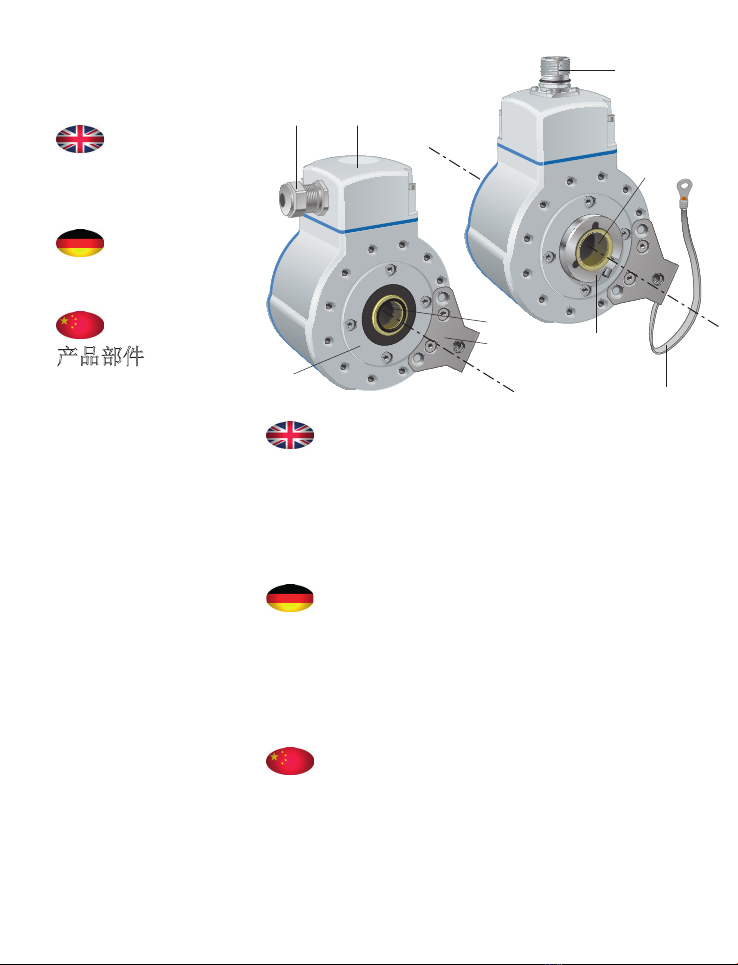
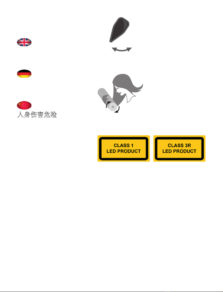
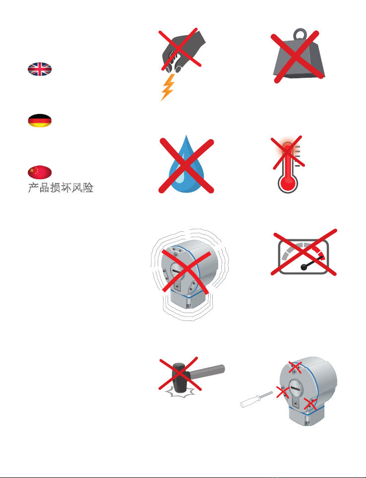
Leine Linde 801 User manual


Mounting instructions
Montageanleitung
安装说明
Encoder models
Drehgebermodelle
编码器型号
801
803
773565-03-A-01
773565-01, ver. 3.0

Contact
Kontakt
联系我们
2
T +46-(0)152-265 00
F +46-(0)152-265 05
www.leinelinde.se
BRASIL
T +55-19-3291 8425
F +55-19-3367 5658
www.leinelinde.com.br
中国
T +86-(021)-52 58 35 66
F +86-(021)-52 58 35 99
www.leinelinde.cn
DANMARK
T +45-862-308 34
www.leinelinde.dk
DEUTSCHLAND
T +49-(0)40-317 675 8-60
F +49-(0)40-317 675 8-65
www.leinelinde.de
ESPAÑA
T +34-93-574 23 02
F +34-93-560 57 60
www.leinelinde.es
INDIA
T +91-11-2617-2504
F +91-11-4058-2516
www.leinelinde.in
ITALIA
T +39-039-596 01 08
F +39-039-971 22 08
www.leinelinde-ltn.it
대한민국
T +82-(0)51-746 5420
F +82-(0)51-746 5421
www.leinelinde.co.kr
SUOMI
T +358-(0)9-561 72 00
F +358-(0)9-561 72 020
info@leinelinde.fi
www.leinelinde.fi
SWEDEN /SVERIGE (Head office)
Box 8, SE-645 21 Strängnäs

Leine &Linde is a Swedish company dedicated to
production of encoders for heavy duty applications.
Some of the values offered by Leine &Linde are local
technical support and possibility of 24 hours express
delivery.
On our website www.leinelinde.com you can find
• data sheets and other product information
• detailed manuals and software for use with pro-
ducts with ADSTM.
Leine &Linde ist ein schwedisches Unternehmen,
das sich auf die Produktion von Drehgebern für den
harten Einsatz in Gewerbe und Industrie speziali-
siert hat. Dabei zeichnet sich Leine&Linde unter
anderem durch kundennahen technischen Support
und mögliche 24-Stunden-Expresslieferungen aus.
Auf unserer Homepage www.leinelinde.de finden Sie
• Datenblätter und sonstige Produktinformationen
• ausführliche Handbücher und Software zur Ver-
wendung von Produkten mit ADSTM.
莱纳林德是一家专门生产重工况应用编码器的瑞典
公司。莱纳林德提供您的一些价值包括本地技术支
持,以及可能安排 24 小时快递送货。
在我们的网站 www.leinelinde.cn 上,您可以找到
• 数据表与其他产品信息
• 详细使用手册和用于 ADSTM 产品的软件。
3

XHI 801
XHI 803
XHI 891
XHI 893
4
The following models are fully covered by these
mounting instructions:
Folgende Modelle werden vollständig von dieser
Montageanleitung abgedeckt:
本安装说明全面涵盖下列型号:
The following models have customised properties
and may deviate slightly from these mounting
instructions:
Folgende Modelle besitzen kundenspezifische
Merkmale und können daher geringfügig von dieser
Montageanleitung abweichen:
下列型号包含有定制特性,可能与本安装说明略
有差异:

5
1
Parts of the
products
Produktteile
产品部件
1.1 Cable gland (adjustable direction)
1.2 Terminal box
1.3 Flange
1.4 Blind hollow shaft
1.5 Torque arm bracket
1.6 Connector (radial direction)
1.7 Through-going hollow shaft
1.8 Clamping ring
1.9 Earthing strap (optional)
1.1 Kabeldurchführung (Richtung verstellbar)
1.2 Klemmenkasten
1.3 Flansch
1.4 Hohlwelle
1.5 Befestigung Drehmomentstütze
1.6 Anschlussstecker (Radialrichtung)
1.7 Durchgehende Hohlwelle
1.8 Klemmring
1.9 Erdungsband (optional)
1.1 电缆密封接头 (可调节方向)
1.2 接线盒
1.3 法兰
1.4 空心轴
1.5 扭矩支架
1.6 连接器 (径向)
1.7 通孔轴
1.8 夹紧环
1.9 接地线 (可选件)
1.1) 1.2)
1.3)
1.4)
1.6)
1.7)
1.8)
1.5)
1.9)

2
Risk of bodily
injury
Verletzungs-
gefahr
人身伤害危险
2.1)
2.2)
6
2.3)
ONOFF

Important before mounting begins:
2.1 Switch off the power.
2.2 Make sure the machine is at a standstill. The
product is to be mounted on a rotating part that
can cause bodily injury when in motion.
2.3 Encoders with Optolink output are designed to
be
• class 1 LED products when used with fibers of
core diameter up to 100 µm
• class 3R LED products when used with fibers of
core diameter of 200 µm.
Wichtig! Vor Beginn der Montage:
2.1 Strom ausschalten.
2.2 Sicherstellen, dass die Maschine stillsteht. Das
Produkt wird auf einem rotierenden Teil mon-
tiert, das im Betrieb eine potenzielle Verletzungs-
gefahr darstellt.
2.3 Drehgeber mit Optolink-Ausgang sind folgender
maßen ausgelegt
• bei Verwendung von Fasern mit einem Kern-
durchmesser von bis zu 100 µm als Produkte
der LED-Klasse 1
• bei Verwendung von Fasern mit einem Kern-
durchmesser von 200 µm als Produkte der LED-
Klasse 3R.
安装前注意事项:
2.1 关闭电源。
2.2 确保机器处于停机状态。本产品安装在旋转部
件上,在运动状态下操作可能导致人身伤害。
2.3 附带 Optolink 输出的编码器,其设计包括
• 用于内径达 100 µm 的光纤时,为第 1 类LED
产品。
• 用于内径达 200 µm 的光纤时,为第 3R 类LED
产品。
7

3
Risk of damage
to the product
Beschädigungs-
gefahr
产品损坏风险
3.1) 3.2)
3.3) 3.4)
3.5) 3.6)
3.7)
8
3.8)
ESD
V

The product is a precision measuring instrument. It
should be handled with care, by experienced person-
nel. The warnings below apply in the event of effects
outside the limit values stated in the product’s data
sheet.
The product may be damaged
3.1 by ESD discharges if the electronics are touched
3.2 if the shaft is exposed to high mechanical forces
3.3 by moisture or chemical fluids (do not install
cable pointing upwards)
3.4 if it is exposed to extreme temperatures
3.5 if it is exposed to powerful vibrations or shock
3.6 by short-circuits or an excessively high supply
voltage
3.7 by impacts or knocks or other physical damage
3.8 if the back cover is opened.
Dieses Produkt ist ein Präzisionsmessgerät. Es muss
daher von geschultem Personal mit Sorgfalt be-
handelt werden. Die nachfolgenden Warnhinweise
gelten für Einwirkungen, die außerhalb der im Pro-
duktdatenblatt angegebenen Grenzwerte liegen.
Schäden am Produkt können durch Folgendes verur-
sacht werden
3.1 durch elektrostatische Entladung bei Berühren
der Elektronik
3.2 durch zu starke Kräfte an der Welle
3.3 durch Feuchtigkeit und chemische Flüssigkeiten
(keine nach oben gerichteten Kabel anbringen)
3.4 durch extreme Temperaturen
3.5 durch zu starke Vibrationen und Erschütte-
rungen
3.6 durch einen Kurzschluss oder eine zu hohe
Betriebsspannung
3.7 durch Schläge, Stöße oder andere physische
Einwirkung
3.8 durch Öffnen des rückseitigen Gehäuses.
本产品为精密测量仪器。应由有经验的人员小心操
作。以下警告适用于,产品在超出技术规范极限值
情况下使用。
产品在下列情况下可能损坏
3.1 电子产品被接触时的静电放电
3.2 轴上作用力过大
3.3 潮湿或化学液体腐蚀 (不要竖直安装电缆)
3.4 极限温度下
3.5 剧烈振动或冲击
3.6 短路或供电电压过高
3.7 遭受敲打,撞击或其他物理损坏
3.8 后盖非正常打开。
9

4.1
Mounting of
blind hollow shaft
Montage der
Sackhohlwelle
空心轴安装
4.2
Mounting of
through-going
hollow shaft
Montage der
durchgehenden
Hohlwelle
通孔轴安装
10
M6
M5 /M6
M5: 5,7 Nm
M6: 9,8 Nm
2,2 Nm
M6
Part from customer Accessories from Leine &Linde (to be ordered separately, see page 20) Tools for mounting
Kundenkomponente Zubehör von Leine &Linde (separate Bestellung, siehe Seite 20) Montagewerkzeug
客户部件 莱纳林德附件 (需单独订 购,参见第 20 页) 安装工具

4.3
Alternative
orientation of
torque bracket
Alternative
Anbringung der
Drehmoment-
stütze
扭矩支架的可选
方位
11
4.4
Alternative
attachment point
for torque arm
Alternative
Anbringung der
Drehmoment-
stütze rückseitig
力矩臂的可选连
接点
Part from customer Accessories from Leine &Linde (to be ordered separately, see page 20) Tools for mounting
Kundenkomponente Zubehör von Leine &Linde (separate Bestellung, siehe Seite 20) Montagewerkzeug
客户部件 莱纳林德附件 (需单独订 购,参见第 20 页) 安装工具
M5

5.2)
5.3)
12
5.4)
M8
M5 / M6
5.1)
5
Check points
for mechanical
mounting
Kontrollpunkte
bei mechanischer
Montage
机械安装检查要
点
90o

13
5.1 Check that the dimensions of the mating shaft
match the specifications in the encoder’s data
sheet. Fix the encoder with an M5 or M6 screw
(ISO 4762) with minimum 9 mm thread in use.
5.2 Fix the encoder with an insulated torque arm.
It must be fitted at 90 degrees angle to the direc-
tion of the bracket, for optimum accuracy of
measurement.
5.3 Check the encoder’s radial runout with slow
rotation of complete assembly. The runout
should not exceed 0.1 mm, as this may shorten
the encoder’s service life or influence the system
accuracy.
5.4 Dismounting; Use M8 screw, if necessary, to
detach the encoder.
5.1 Sicherstellen, dass die Abmessungen der Gegen-
welle den Angaben im Drehgeber-Datenblatt
entsprechen. Drehgeber mit einer M5- bzw. M6-
Schraube (ISO 4762) mit mindestens 9-mm-
Gewinde befestigen.
5.2 Drehgeber mit einer isolierten Drehmoment-
stütze befestigen. Um eine optimale Messgenau-
igkeit erzielen zu können, muss die Drehmo-
mentstütze im 90-Grad-Winkel zur Befestigung
montiert werden.
5.3 Radialversatz des Drehgebers bei langsamer
Rotation und fertiger Montage überprüfen. Der
Versatz darf 0,1 mm nicht überschreiten, da
sonst die Lebensdauer des Drehgebers verkürzt
bzw. die Systemgenauigkeit beeinträchtigt
werden kann.
5.4 Demontage: Bei Bedarf beim Drehgeberwechsel
M8-Schraube zum Lösen verwenden.
5.1 检查连接轴的尺寸是否符合编码器数据表中的
规格。使用 M5 或M6 螺丝 (ISO 4762) 配合最
小9 mm 螺纹来固定编码器。
5.2 使用绝缘扭矩臂固定编码器。安装角度必须和
托架方向成 90 度,以确保最佳的测量精度。
5.3 通过完整组件的慢速旋转来检查编码器的径向
偏移。偏移不应超过 0.1 mm,否则将缩短编码
器的使用寿命或影响系统的精度。
5.4 如有需要,使用 M8 螺丝以在更换时拆卸编码
器。

1)
2)
3)
4)
10 mm 8 mm
100 mm
ø8-11 mm
14
6
Electrical
mounting
Elektrische
Montage
电气安装

Fit cable*, using the following steps:
Step 1. Strip the cable according to the dimensions
in the illustration.
Step 2. Open the terminal box and unscrew the
cable bushing.
Step 3. Fold the cable shield backwards over the
shell ring.
Step 4. Connect the wires according to the product
label. Insulate any wire that is not being
used. Tighten all terminal screws and en-
sure that each block is screwed tight into
the correct mating socket (one for 6 termi-
nals, one for 7).
* Does not apply to models with pre-installed cable
or connector.
Die elektrische Montage des Kabels*:
Schritt 1.Kabel gemäß den Maßangaben in der
Abbildung abisolieren.
Schritt 2.Klemmenkasten öffnen und Kabeldurch-
führungen aufschrauben.
Schritt 3.Kabelschirm über den Mantelring nach
hinten biegen.
Schritt 4.Leitung gemäß der Belegung wie auf dem
Etikett angegeben anschließen. Nicht ver-
wendete Leiter isolieren. Sämtliche Klem-
menschrauben anziehen und sicherstellen,
dass jeder Block fest in die richtige Buchse
geschraubt wird (eine für 6 Klemmen, eine
für 7).
* Gilt nicht für Modelle mit vormontiertem Kabel
oder Anschlussstecker.
通过下列步骤安装电缆*:
第1步: 按照图示尺寸剥开电缆。
第2步: 打开接线盒,拧下电缆套管。
第3步: 将电缆屏蔽层向后对折包在环箍上。
第4步: 按照产品标签所示意接线。并对未使用导
线进行绝缘处理。将所有固定螺丝锁紧,
确定每组都锁紧到正确的接头上 (一组 6
个,一组 7 个)。
*不适用于预安装了电缆或连接器的型号。 15

7.2)
7.3)
7.4)
7.6)
L < Lmax
7.1)
>200mm >100mm >100mm
R 40 mm R 100 mm
16
> >
7.5)
7
Check points for
electrical mount-
ing
Kontrollpunkte
bei elektrischer
Montage
电气安装检查要
点

7.1 Use a shielded twisted-pair cable. The shielding
must be connected to the chassis at both ends
and be earthed at one point.
7.2 Keep potential sources of disturbance at the rec-
ommended distance from the cable. Make sure
that the length of the cable does not exceed the
value specified in the product data sheet.
7.3 Ensure that the cable’s bending radius exceeds
the permitted minimum value.
7.4 Treat all wires as live. Any wires not in use must
be insulated.
7.5 Check that the green LED lights up when the
power is switched on. The red LED indicates en-
coder fault.
7.6 If the product comes with an earthing strap, this
must be connected to the chassis of the machine.
7.1 Verwenden Sie ein geschirmtes, paarig verseiltes
Kabel. Der Schirm soll auf beiden Seiten aufge-
legt und an einer Stelle geerdet werden.
7.2 Potenzielle Störquellen auf empfohlenem Ab-
stand halten. Sicherstellen, dass die Kabellänge
nicht den im Produktdatenblatt angegebenen
Wert überschreitet.
7.3 Sicherstellen, dass der Biegeradius des Kabels
über dem zulässigen Mindestwert liegt.
7.4 Sämtliche Leiter als stromführend betrachten.
Nicht genutzte Leiter isolieren.
7.5 Sicherstellen, dass beim Einschalten die LED
grün leuchtet. Rot deutet auf einen Defekt oder
Anschlussfehler hin.
7.6 Wird das Produkt mit einem Erdungsband gelie-
fert, ist dieses an das Maschinengestell anzu-
schließen.
7.1 使用屏蔽双绞线电缆。屏蔽电缆必须连接到底
座两端,并单点接地。
7.2 请将潜在干扰源放置在离电缆建议的距离外。
确保电缆长度不超过产品数据表中的规定值。
7.3 确保电缆的弯曲半径超过所允许的最小值。
7.4 将所有导线视为带电线路。必须对所有未使用
的导线做绝缘处理。
7.5 检查当打开电源时,绿色 LED 是否亮起。红色
LED 表示编码器发生故障。
7.6 如果产品有接地带,必须将其连接到底座。 17

Leine&Linde products conform to several standards
and approvals. Certificates and documentation may
be provided upon request to your local Leine&Linde
representative.
8.1 UL/CSA standards, type approval
Most Leine&Linde products have been type
tested in accordance with IEC 61010. The product
box label states if the product conforms to the
standard. When the product is to be operated
in accordance with IEC 61010-1, the power must
be supplied from an isolated secondary circuit
with current or energy or power limitation as
per IEC 61010-1, IEC 60950-1, or by a class 2
secondary circuit as specified in UL 1310.
8.2 CE marking and Declaration of conformity
Most Leine&Linde products conform to the
protection requirements of Council Directive
2014/30/EU related to EMC when applicable.
The product box label states if the product
conforms to the standard.
8.1)
8.2)
8
Certificates and
approvals
Zertifikate und
Zulassungen
执照和认证标准
18

Produkte von Leine&Linde erfüllen die Auflagen
einer Reihe von Normen und Zulassungen. Auf
Anfrage sind Zertifikate und Dokumentation beim
Leine&Linde-Vertreter in Ihrer Nähe erhältlich.
8.1 Zulassung gemäß UL-/CSA-Normen
Die meisten Produkte von Leine&Linde wurden
gemäß IEC 61010 typgeprüft. Bei Verwendung
des Produkts gemäß IEC 61010-1 muss die
Spannungsversorgung aus einem isolierten
Sekundärkreis mit Strom-, Energie- oder Leis-
tungsbegrenzung nach IEC 61010-1, IEC 60950-1,
bzw. aus einem Sekundärkreis der Klasse 2 nach
UL 1310 erfolgen.
8.2 CE-Kennzeichnung und Konformitätserklärung
Die meisten Produkte von Leine&Linde erfüllen
die EMV-Sicherheitsanforderungen gemäß Richt-
linie 2014/30/EU (sofern anwendbar). Auf der
Produktverpackung ist angegeben, ob das Produkt
der jeweiligen Norm entspricht.
莱纳林德的产品符合多项认证标准。请向您当地的
莱纳林德代表索取有关认证证书和认证文件。
8.1 UL/CSA 标准
按类别批准 莱纳林德的大多数产品都遵照
IEC 61010 类别进行测试。产品包装盒上的标
签列明该产品是否符合标准。如果产品要符
合 IEC 61010-1 标准运行,其电力必须由独立
的二次电路供应,且电流或能源或电力极限需
符合 IEC 61010-1、IEC 60950-1,或依照
UL 1310 所定规格的第 2 类二次电路。
8.2 CE 标识和符合性声明
莱纳林德的大多数产品都符合欧盟电磁兼容性
2014/30/EU 指令的保护要求。产品包装盒上
的标签列明该产品是否符合标准。
19
This manual suits for next models
5
Table of contents
Other Leine Linde Media Converter manuals
Popular Media Converter manuals by other brands

Allied Telesis
Allied Telesis AT-MC102XLPCI installation guide

AV TOOL
AV TOOL AVT-2050 instruction manual

EDWANZ group
EDWANZ group Deutronic DVC Series Installation and safety instructions

Metel
Metel BREAK-DW-S-4C Series quick start guide

TC Communications
TC Communications TC3020R user manual

Lindy
Lindy 32870 Installation and use

Seneca
Seneca Z-4RTD2 installation manual

GLT
GLT DD-6 User instruction

Antrica
Antrica ANT-6000E Specification & user manual

Alba Fiber Systems
Alba Fiber Systems AFS6000 Series Installation & operation instructions

Cambridge Audio
Cambridge Audio DacMagic XS user manual

ANTAIRA
ANTAIRA IMP-C100 Series Quick installation guide