9
JBL Professional
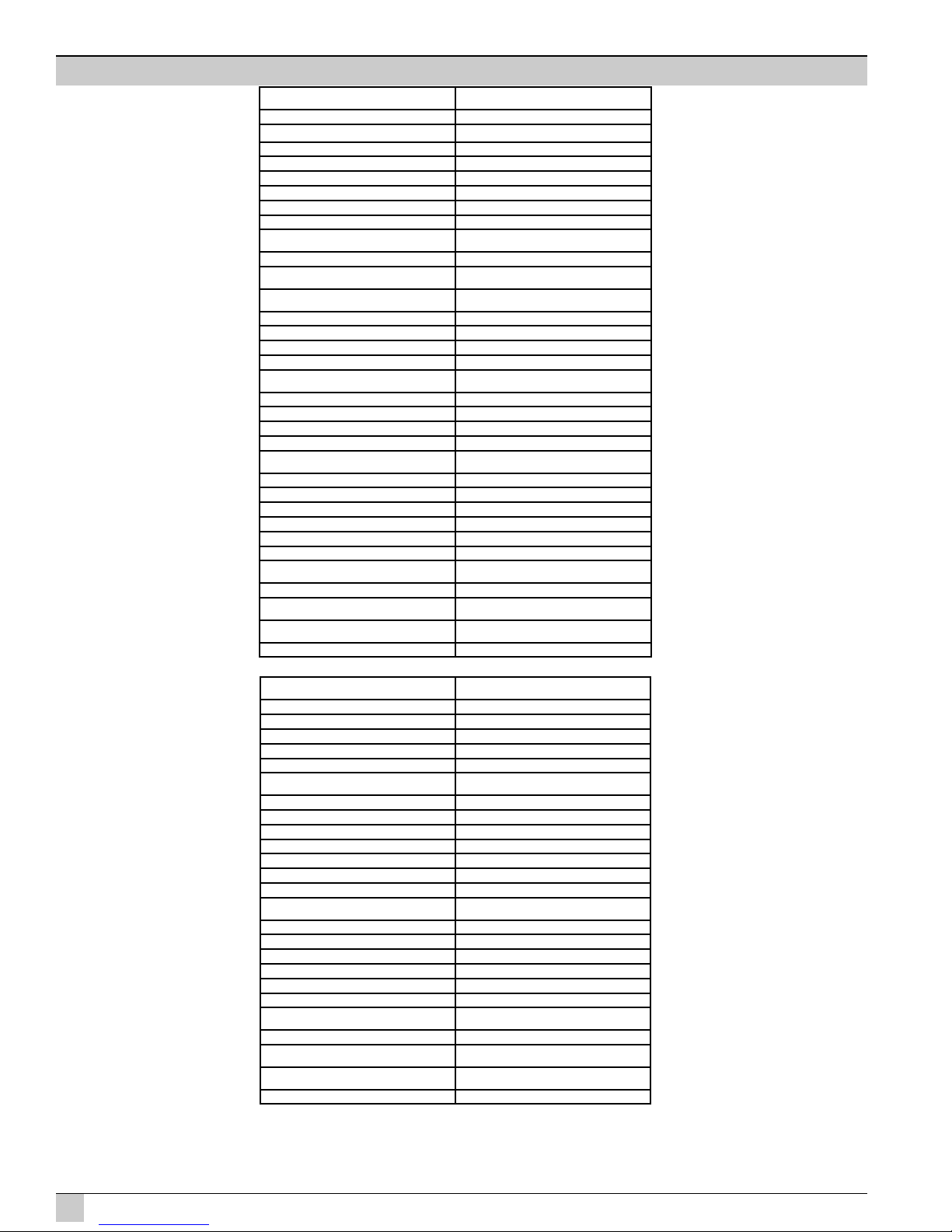
VP SERIES SYSTEMS SPECIFICATIONS
VP7215/64DP
Specifications:
Frequency Response (+/-3dB): 60 Hz - 18 kHz
Frequency Range (-10dB): 45 Hz - 20 kHz
Coverage Pattern: 60° x 40° rotatable waveguide
Directivity Factor (Q): 15.8
Directivity Index (DI): 12 dB
Max Peak Output: 137 dB SPL 1m
Transducer Section:
Low Frequency Section: JBL 2265G, 381 mm (15 in) dia., 76 mm (3 in) Dual
Coil neodymium Differential Drive®, Direct Cooled
Bandpass Nominal Impedance: 4 ohms
High Frequency: JBL2452H-SL, 100 mm (4 in) titanium damped
diaphragm, 1.5 in. exit.
Bandpass Nominal Impedance: 8 ohms
System:
DP2 Internal Amplification Output (at nominal load): 2200 Watts Peak (1100 Watts Continuous)
DP2 Output (Continuous IEC shaped pink noise
into rated load impedance):
750LF/350HF Watts
DP2 Output Section: 2-Channel, Class I
Audio Input Connector: XLR with loop-through
Network Control Connector: Ethernet, RJ45 (DPAN, DPCN options)
Signal Processing: DSP based, resident in Input Module.
System Management: DSP based limiters for mechanical and thermal
protection
AC Power Operating Range: Auto Select 90-132VAC/216-264VAC, 50/60 Hz
AC Line Voltage: 50/60 Hz, Auto-Detect; 120V/240V (-15%, +10%)
AC Input Connector: Neutrik PowerCon
AC Loop-Thru: Neutrik PowerCon
AC Current Requirement: 6A per system at 120V, 3A per system at 240V
Enclosure:
Box Construction: 5/8 in. multi-ply exterior grade Baltic birch.
Internally braced. Black DuraFlex™ finish.
Suspension System: 6 standard air-cargo 3 in. track and 14 M10 fittings.
Grille: 14 Gauge Black, powder-coated perforated steel
with foam backing.
Dimensions (H x W x D): 765.3 x 447.6 x 523.5 mm
30.13 x 17.62 x 20.61 in.
Net Weight: 38.6 kg (85 lb)
VP7215/95DP
Specifications:
Frequency Response (+/-3dB): 60 Hz - 18 kHz
Frequency Range (-10dB): 45 Hz - 20 kHz
Coverage Pattern: 90° x 50° rotatable waveguide
Directivity Factor (Q): 12.6
Directivity Index (DI): 11 dB
Max Peak Output: 137 dB SPL 1m
Transducer Section:
Low Frequency Section: JBL 2265G, 381 mm (15 in) dia., 76 mm (3 in) Dual
Coil neodymium Differential Drive®, Direct Cooled
Bandpass Nominal Impedance: 4 ohms
High Frequency: JBL2452H-SL, 100 mm (4 in) titanium damped
diaphragm, 1.5 in. exit.
Bandpass Nominal Impedance: 8 ohms
System:
DP2 Internal Amplification Output (at nominal load): 2200 Watts Peak (1100 Watts Continuous)
DP2 Output (Continuous IEC shaped pink noise
into rated load impedance):
750LF/350HF Watts
DP2 Output Section: 2-Channel, Class I
Audio Input Connector: XLR with loop-through
Network Control Connector: Ethernet, RJ45 (DPAN, DPCN options)
Signal Processing: DSP based, resident in Input Module.
System Management: DSP based limiters for mechanical and thermal
protection
AC Power Operating Range: Auto Select 90-132VAC/216-264VAC, 50/60 Hz
AC Line Voltage: 50/60 Hz, Auto-Detect; 120V/240V (-15%, +10%)
AC Input Connector: Neutrik PowerCon
AC Loop-Thru: Neutrik PowerCon
AC Current Requirement: 6A per system at 120V, 3A per system at 240V
Enclosure:
Box Construction: 5/8 in. multi-ply exterior grade Baltic birch.
Internally braced. Black DuraFlex™ finish
Suspension System: 6 standard air-cargo 3 in. track and 14 M10 fittings
Grille: 14 Gauge Black, powder-coated perforated steel
with foam backing.
Dimensions (H x W x D): 765.3 x 447.6 x 523.5 mm
30.13 x 17.62 x 20.61 in.
Net Weight: 38.6 kg (85 lb)
VP7212/64DP
Specifications:
Frequency Response (+/-3dB): 63 Hz - 18 kHz
Frequency Range (-10dB): 47 Hz - 20 kHz
Coverage Pattern: 60° x 40° rotatable waveguide
Directivity Factor (Q): 15.8
Directivity Index (DI): 12 dB
Max Peak Output: 136 dB SPL 1m
Transducer Section:
Low Frequency Section: JBL 2262G, 304 mm (12 in) dia., 76 mm (3 in) Dual
Coil neodymium Differential Drive®, Direct Cooled
Bandpass Nominal Impedance: 4 ohms
High Frequency: JBL2452H-SL, 100 mm (4 in) titanium damped
diaphragm, 1.5 in. exit.
Bandpass Nominal Impedance: 8 ohms
System:
DP2 Internal Amplification Output (at nominal load): 2200 Watts Peak (1100 Watts Continuous)
DP2 Output (Continuous IEC shaped pink noise
into rated load impedance):
750LF/350HF Watts
DP2 Output Section: 2-Channel, Class I
Audio Input Connector: XLR with loop-through
Network Control Connector: Ethernet, RJ45 (DPAN, DPCN options)
Signal Processing: DSP based, resident in Input Module.
System Management: DSP based limiters for mechanical and thermal
protection
AC Power Operating Range: Auto Select 90-132VAC/216-264VAC, 50/60
AC Line Voltage: 50/60 Hz, Auto-Detect; 120V/240V (-15%, +10%)
AC Input Connector: Neutrik PowerCon
AC Loop-Thru: Neutrik PowerCon
AC Current Requirement: 6A per system at 120V, 3A per system at 240V
Enclosure:
Box Construction: 5/8 in. multi-ply exterior grade Baltic birch. Inter-
nally braced. Black DuraFlex™ finish
Suspension System: 6 standard air-cargo 3 in. track and 14 M10 fittings.
Grille: 14 Gauge Black, powder-coated perforated steel
with foam backing.
Dimensions (H x W x D): 701.8 x 383.8 x 523.5 mm
27.63 x 15.11 x 20.61 in.
Net Weight: 35.4 kg (78 lb)
VP7212/95DP
Specifications:
Frequency Response (+/-3dB): 63 Hz - 18 kHz
Frequency Range (-10dB): 47 Hz - 20 kHz
Coverage Pattern: 90° x 50° rotatable waveguide
Directivity Factor (Q): 12.6
Directivity Index (DI): 11 dB
Max Peak Output: 136 dB SPL 1m
Transducer Section:
Low Frequency Section: JBL 2262G, 304 mm (12 in) dia., 76 mm (3 in) Dual
Coil neodymium Differential Drive®, Direct Cooled
Bandpass Nominal Impedance: 4 ohms
High Frequency: JBL2452H-SL, 100 mm (4 in) titanium damped
diaphragm, 1.5 in. exit.
Bandpass Nominal Impedance: 8 ohms
System:
DP2 Internal Amplification Output (at nominal load): 2200 Watts Peak (1100 Watts Continuous)
DP2 Output (Continuous IEC shaped pink noise
into rated load impedance):
750LF/350HF Watts
DP2 Output Section: 2-Channel, Class I
Audio Input Connector: XLR with loop-through
Network Control Connector: Ethernet, RJ45 (DPAN, DPCN options)
Signal Processing: DSP based, resident in Input Module.
System Management: DSP based limiters for mechanical and thermal
protection
AC Power Operating Range: Auto Select 90-132VAC/216-264VAC, 50/60
AC Line Voltage: 50/60 Hz, Auto-Detect; 120V/240V (-15%, +10%)
AC Input Connector: Neutrik PowerCon
AC Loop-Thru: Neutrik PowerCon
AC Current Requirement: 6A per system at 120V, 3A per system at 240V
Enclosure:
Box Construction: 5/8 in. multi-ply exterior grade Baltic birch.
Internally braced. Black DuraFlex™ finish
Suspension System: 6 standard air-cargo 3 in. track and 14 M10 fittings.
Grille: 14 Gauge Black, powder-coated perforated steel
with foam backing.
Dimensions (H x W x D): 701.8 x 383.8 x 523.5 mm
27.63 x 15.11 x 20.61 in.
Net Weight: 35.4 kg (78 lb)