manuals.online logo
Brands
  1. Home
  2. •
  3. Brands
  4. •
  5. JBL
  6. •
  7. Subwoofer
  8. •
  9. JBL Cinemavision CVSUB50 User manual

JBL Cinemavision CVSUB50 User manual

Other JBL Subwoofer manuals

JBL GT1000T User manual

JBL

JBL GT1000T User manual

JBL SUB500 User manual

JBL

JBL SUB500 User manual

JBL Grand Touring GTO1204BP User manual

JBL

JBL Grand Touring GTO1204BP User manual

JBL P1222 User manual

JBL

JBL P1222 User manual

JBL PowerBass PB10 User manual

JBL

JBL PowerBass PB10 User manual

JBL SUB 100P User manual

JBL

JBL SUB 100P User manual

JBL CS80 User manual

JBL

JBL CS80 User manual

JBL BASSPRO User manual

JBL

JBL BASSPRO User manual

JBL Bass2/Basswave User manual

JBL

JBL Bass2/Basswave User manual

JBL PSW1000 User manual

JBL

JBL PSW1000 User manual

JBL P1222 Instruction manual

JBL

JBL P1222 Instruction manual

JBL P1020DII User manual

JBL

JBL P1020DII User manual

JBL CS1215B User manual

JBL

JBL CS1215B User manual

JBL Studio S26 User manual

JBL

JBL Studio S26 User manual

JBL PS60 User manual

JBL

JBL PS60 User manual

JBL L10CS User manual

JBL

JBL L10CS User manual

JBL Grand Touring GTO1014 User manual

JBL

JBL Grand Touring GTO1014 User manual

JBL PSWD115 User manual

JBL

JBL PSWD115 User manual

JBL III SERIES User manual

JBL

JBL III SERIES User manual

JBL Grand Touring GTO1204BP User manual

JBL

JBL Grand Touring GTO1204BP User manual

JBL PowerBass PB10 User manual

JBL

JBL PowerBass PB10 User manual

JBL Grand Touring GTO1014 User manual

JBL

JBL Grand Touring GTO1014 User manual

JBL SCS 138-178 User manual

JBL

JBL SCS 138-178 User manual

JBL E250P User manual

JBL

JBL E250P User manual

Popular Subwoofer manuals by other brands

Sony XS-AW8 operating instructions

Sony

Sony XS-AW8 operating instructions

Sony XS-L836 Specifications

Sony

Sony XS-L836 Specifications

B&C Speakers 15 HPL 76W Specifications

B&C Speakers

B&C Speakers 15 HPL 76W Specifications

Velodyne DD-18+ Specifications

Velodyne

Velodyne DD-18+ Specifications

Sonance Cinema Series SUB 10-150 Specifications

Sonance

Sonance Cinema Series SUB 10-150 Specifications

Hifonics HW-12 Owners & installation manual

Hifonics

Hifonics HW-12 Owners & installation manual

Magnat Audio ADR 130 BP user manual

Magnat Audio

Magnat Audio ADR 130 BP user manual

Blitz BZP106 Specifications

Blitz

Blitz BZP106 Specifications

Technics SB-AS500 Operaing instructions

Technics

Technics SB-AS500 Operaing instructions

Lyngdorf BW-2 owner's manual

Lyngdorf

Lyngdorf BW-2 owner's manual

Lyngdorf BW-3 owner's manual

Lyngdorf

Lyngdorf BW-3 owner's manual

Pyle Pro PYLE PRO PDW15125 owner's manual

Pyle Pro

Pyle Pro PYLE PRO PDW15125 owner's manual

REL Acoustics Q Series operating instructions

REL Acoustics

REL Acoustics Q Series operating instructions

L-Acoustics KIVA SB15M Rigging manual

L-Acoustics

L-Acoustics KIVA SB15M Rigging manual

Pioneer Elite S-W1EX Service manual

Pioneer

Pioneer Elite S-W1EX Service manual

B&C Speakers Woofer 12 HPL 76 specification

B&C Speakers

B&C Speakers Woofer 12 HPL 76 specification

KEF KUBE 200 installation manual

KEF

KEF KUBE 200 installation manual

Yamaha SW500 owner's manual

Yamaha

Yamaha SW500 owner's manual

manuals.online logo
manuals.online logoBrands
  • About & Mission
  • Contact us
  • Privacy Policy
  • Terms and Conditions

Copyright 2025 Manuals.Online. All Rights Reserved.

Cinemavision™Subwoofer
CVSUB50
Service Manual
JBL Consumer Products
250 Crossways Park Dr.
Woodbury, New York 11797 Rev1 10/2005
- CONTENTS -
BASIC SPECIFICATIONS …………….……..…………..1
DETAILED SPECIFICATIONS ……….……..…………..2
OPERATION ……..………………….……...…….….…...4
CONNECTIONS………………………...……..…...…..…5
BASIC TROUBLESHOOTING……………………………6
EXPLODED VIEW/PARTS LIST…….….….…………....7
TEST SET-UP AND PROCEDURE….………………….8
BLOCK DIAGRAM….……………………………………..9
ELECTRICAL PARTS LIST……………………………..10
P.C.B. DRAWINGS….……………...........................….13
IC/TRANSISTOR PINOUTS..……..….…….….….….….16
SCHEMATICS………..……………………….…………..17
PACKING……..…….....................................................27
CVSUB50 SPECIFICATIONS
Amplifier Power (RMS): 400 Watts
Driver: 12" (305mm) PolyPlas™
Inputs: LFE Preamp level
Frequency Response: 22Hz – Low-pass crossover setting at signal
source
Dimensions (H x W x D): 18-3/4" x 12" x 18-1/4"
(476mm x 305mm x 464mm)
Weight: 49 lb/22.3kg
JBL continually strives to update and improve existing products, as well as create new ones. The
specifications and details in this and related JBL publications are therefore subject to change without
notice.
1
Cinema Vision Subwoofer CVSUB50
LINE VOLTAGE Yes/No Hi/Lo Line Nom. Unit Notes
US 120vac/60Hz Yes 108-132 120 Vrms Normal Operation
EU 230vac/50-60Hz Yes 207-264 230 Vrms Normal operation, MOMS required
Asia 100vac/50Hz Yes 90-110 100 Vrms Normal Operation
Parameter Specification Unit QA Test
Limits Conditions Notes
Amp Section
Type (Class AB, D, other) D ---
Load Impedance (speaker) 4 Ohms Nominal Z-curve required
Rated Output Power 290 Watts Regulated 125 V line 5% tolerance applies
THD@ Rated Power 1 % 22k filter, 50Hz 290 W +/- 5 %
THD @ 1 Watt 0.2 % 22k filter, 50Hz
DC Offset N/A mV-DC < 20 @ Speaker Outputs
Damping factor 20 N/A > 15 measured at 50 Hz
Input Sensitivity
Line Input 350 mVrms 300 W @ 120Hz
Speaker/Hi Level Input N/A
Signal to Noise
SNR-A-Weighted 100 dBA relative to rated power A-Weighting filter
SNR-unweighted 70 dBr relative to rated power 22k filter
SNR rel. 1W-unweighted 60 dBr relative to 1W Output 22k filter
Residual Noise Floor 2 mVrms Volume @ max, using RMS reading DMM/VOM (or A/P)
Residual Noise Floor 1 mVrms(max) Volume @ max, w/ A/P Swept Bandpass Measurement (Line freq.+ harmonics)
Input Impedance
Line Input 5 k ohms Nominal
Active Filters
Low Pass (fixed or variable) FIXED --
Frequency 240 Hz
Slope 12 dB/Octave
Q Butterworth Damping
Subsonic filter (HPF) FIXED --
Frequency 31 Hz
Slope 12 dB/Octave
Q 1.5 Damping
Friend Circuit FIXED --
Frequency 62 Hz Hz notch filter
Slope 12 dB/Octave
Q 3 Damping
Switches
Main Power ON/OFF YES --
Type push-button -- Located on amp plate TV-8
Polarity Switch YES -- "DOWN": 0°; "UP": 180°
Type mini togle -- Located on amp plate
Limite
r
(yes/no) YES compressor and limiter
THD at Max. Output Power less than 2 % Maximum Output Power Maximum THD as a result of limiting.
Output Volume Control
Volume Control Pot YES -- Located on amp plate
Taper (lin/log) log A taoer --
@ minimum setting no output
Input/Output Configuration
LFE In YES -- RCA phono jack, gold with purple insulator
Signal Sensing (ATO)
Auto-Turn-On (yes/no) YES --
ATO Input Test Frequency 100 Hz
ATO Input Threshold 2 mV typ.
ATO Low Pass cutoff 400 Hz 450 ATO-LPF for noise immunity
ATO Turn-on time 1 ms 10 Amp connected and AC on, then input signal applied ( 1 W output )
Auto Mute / Turn-OFF Time 10 minutes 5 < t < 15 Time before muting, after signal is removed
Power on Features
Power on Delay time greater than 2 sec. When AC Power is Applied
Power on LED YES -- bi-color LED located remotely on port facia
Normal On/Off green / red color ATO mode only ( no manual overide )
ATO -- color "Active": green; "Standby": red
Transients/Pops
ATO Transient 5 mV-peak @ Speaker Output
Turn-on Transient 30 mV-peak @ Speaker Output AC Line cycled from OFF to ON
Turn-off Transient 30 mV-peak @ Speaker Output AC Line cycled from ON to OFF
CVSUB50
2
Parameter Specification Unit QA Test
Limits Conditions Notes
Efficiency
Stand-by Input Power 12 Watts typ. @ nom. line voltage
AC Power Cons.@1W 13 Watts typ. @ nom. line voltage
Power Cons.@rated power 375 Watts typ. @ nom. line voltage Input power measured is REAL Watts, not VA
Efficiency 70 % typ. @ nom. line voltage
Protection
Short Circuit Protection YES -- Direct short at output
Thermal Protection YES -- threshold ~ 65 deg. C at panel
DC Offset Protection YES -- DC present at Speaker Out leads Relay for driver/fire protection
Line Fuse Rating ( 120 V ) 3.15 Amps Type ADL or MDL Internal panel mount fuse holder
CVSUB50
3
10
SUBWOOFER OPERATION
Press the Master Power
switch (marked “Power” å)
in to the On position to use
the subwoofer. The CVSUB50
subwoofer will automatically
turn on or go into standby
(sleep) mode as described
below. When your receiver
or amplifier is off, or is not
sending program material to
the subwoofer, the sub-
woofer will be in standby
mode (LED on front of
CVSUB50 will be red). When
the sub
woofer senses an
audio signal,
it will automati-
cally turn on (LED will be
green). If the subwoofer
does not sense a signal after
approximately 20 minutes,
it
will automatically go into
standby mode.
If you will be away from
home for an extended period
of time, or if the subwoofer
will not be used, switch the
Master Power switch åto
the Off position by pressing
it until it pops out.
VOLUME
∫
å
ç
Volume may be adjusted
using the Subwoofer Level
control ∫as shown.
The Phase Control deter-
mines whether the sub-
woofer’s piston-like action
moves in and out in phase
with the main speakers or
opposite the main speakers.
There is no correct or incor-
rect setting. Proper phase
adjustment depends on sev-
eral variables, such as sub-
woofer placement and lis-
tener position. Adjust the
Phase Switch çto maxi-
mize bass output at the
listening position.
Remember, every system,
room and listener is differ-
ent. There are no right or
wrong settings; this switch
offers the added flexibility to
adjust your subwoofer for
optimum performance for
your specific listening condi-
tions without having to move
your speakers. If at some
time in the future you hap-
pen to rearrange your listen-
ing room and move your
speakers, you should experi-
ment with the phase switch
in both positions, and leave it
in the position that maxi-
mizes bass performance.
MIN MAX
Subwoofer
Level
MIN MAX
Subwoofer
Level
CV OM 6/15/04 4:06 PM Page 10
CVSUB50
4
9
The CVSUB50 subwoofer
is equipped with only one
input – a dedicated low-
frequency effects (LFE) input.
Since the LFE channel is by
definition limited to only the
lowest portion of the fre-
quency spectrum, it is cru-
cial that your receiver’s out-
put be compatible. The
CVSUB50 should only be
used with receivers or
processors that have digital
surround decoders, such as
Dolby* Digital or DTS.®Do
not use the CVSUB50 with
components that output a
full-range signal through the
subwoofer output or with
components that only have
a line-level (preamp) output,
unless an outboard low-pass
crossover is used to filter the
signal.
Use the line-level input jack
marked “LFE” for the low-
frequency effects channel.
Connect this jack to the LFE
(subwoofer) output on your
receiver or processor.
Connect each speaker to
the corresponding speaker
terminals on your receiver
or amplifier.
Make sure that you have
configured your surround
sound processor for “Sub-
woofer On.” Also configure
your receiver for 5.1-, 6.1-
or 7.1-channel operation, as
appropriate. The front left,
front right, center and rear
speakers should all be set
to “Small.” If your receiver
allows you to set the cross-
over frequency between
the subwoofer and the main
speakers, select
90Hz or the
setting that is the closest
frequency below it (80Hz if
available).
SYSTEM CONNECTION
– +
– +
– +
– +
– +
– +
– +
– +– +
Receiver
Subwoofer
(LFE) Out
Left
Front
Left
Surround – +
Right
Front
Right
Surround
Subwoofer
Center
Surround Back
Left
LFE In
Right Surround
Right Front
Left Surround
Left Front Center
– +
Surround Back
Left
– +
– +
Surround Back
Right
– +
Surround Back
Right
CV OM 6/15/04 4:06 PM Page 9
CVSUB50
5
If there is no sound from any
of the speakers:
• Check that receiver/ampli-
fier is on and a source is
playing.
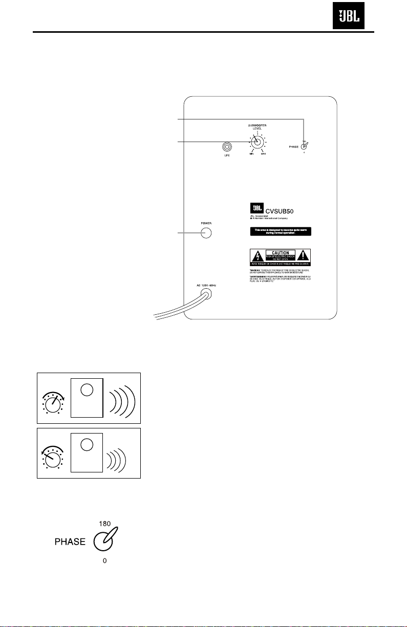
• Check that the powered
subwoofer is plugged in,
and is turned on
(Power
switch åpushed in).
• Check all wires and con-
nections between receiver/
amplifier and speakers.
Make sure all wires are con-
nected. Make sure none of
the speaker wires are
frayed, cut or punctured, or
touching each other.
• Review proper operation of
your receiver/amplifier.
If there is no sound coming
from one speaker:
• Check the “Balance” control
on your receiver/amplifier.
• Check all wires and con-
nections between receiver/
amplifier and speakers.
Make sure all wires are con-
nected. Make sure none of
the speaker wires are
frayed, cut or punctured, or
touching each other.
• In Dolby Digital or DTS
modes, make sure that the
receiver/processor is config-
ured so that the speaker in
question is enabled.
• Turn off all electronics
and switch the speaker in
question with one of the
other speakers that is work-
ing correctly. Turn every-
thing back on, and deter-
mine whether the problem
has followed the speaker, or
has remained in the same
channel. If the problem is
in the same channel, the
source of the problem
is most likely with your
receiver or amplifier, and
you should consult the
owner’s manual for that
product for further informa-
tion. If the problem has fol-
lowed the speaker, consult
your dealer for further assis-
tance or, if that is not possi-
ble, visit www.jbl.com.
If there is no sound from the
center speaker:
• Check all wires and con-
nections between receiver/
amplifier and speaker. Make
sure all wires are connected.
Make sure none of the
speaker wires are frayed,
cut or punctured, or touch-
ing each other.
• If your receiver/processor
is set in Dolby Pro Logic mode,
make sure the center speaker
is not in phantom mode.
• If your receiver/processor
is set in one of the Dolby
Digital or DTS
modes, make
sure the receiver/
processor
is configured so that the
center speaker is enabled.
If the system plays at low
volumes but shuts off as
volume is increased:
• Check all wires and con-
nections between receiver/
amplifier and speakers.
Make sure all wires are con-
nected. Make sure none of
the speaker wires are
frayed, cut or punctured, or
touching each other.
• If more than one pair of
main speakers is being used,
check the minimum imped-
ance requirements of your
receiver/amplifier.
If there is low (or no) bass
output:
• Make sure the connections
to the left and right “Speaker
Inputs” have the correct
polarity (+ and –).
• Make sure the subwoofer
is plugged into an active
electrical outlet
, and is
turned on (Power switch
åpushed in).
• In Dolby Digital or DTS
modes, make sure your
receiver/processor is config-
ured so that the subwoofer
and LFE output are enabled.
• Switch the Phase Switch
çto the opposite position,
and select the position that
results in the most pleasing
bass response.
If there is no sound from
the surround speakers:
• Check all wires and con-
nections between receiver/
amplifier and speakers.
Make sure all wires are con-
nected. Make sure none of
the speaker wires are
frayed, cut or punctured, or
touching each other.
• Review proper operation of
your receiver/amplifier and
its surround sound features.
• Make sure the movie or
TV show you are watching
is recorded in a surround
sound mode. If it is not,
check to see whether your
receiver/amplifier has other
surround modes you may use.
•
In Dolby Digital or DTS
modes, make sure your
receiver/processor is config-
ured so that the surround
speakers are enabled. When
five satellites are in use,
remember to configure your
receiver or processor for
6.1-channel operation, and
when six satellites are in use,
configure your receiver or
processor for 7.1 channels.
• Review the operation of
your DVD player and the
jacket of your DVD to make
sure that the DVD features
the desired Dolby Digital or
DTS mode, and that you
have properly selected that
mode using both the DVD
player’s menu and the DVD
disc’s menu.
TROUBLESHOOTING
11
CV OM 6/15/04 4:06 PM Page 11
CVSUB50
6
CVSUB50
7
CVSUB50 TEST PROCEDURE
SYSTEM AURAL SWEEP TEST
Equipment needed:
•Function/signal generator/sweep generator
•Multimeter
•Integrated Amplifier
•Speaker Cables
General Unit Function (UUT = Unit Under Test)
Phase switch – either position
1) Connect the LFE jack to a signal generator with RCA cable.
2) On the front of the unit, turn the LEVEL control full
counterclockwise (MIN).
3) Turn on generator, adjust to 150mV, 50 Hz.
4) Plug in UUT; turn the power switch ON. Turn LEVEL control full clockwise (MAX)
5) LED should now be Green; immediate bass response should be heard and felt from port tube opening.
6) Turn off generator, turn LEVEL control fully counterclockwise (MIN), disconnect RCA cable.
Sweep Function
1) Follow steps 1-4 above, using a sweep generator as a signal source.
2) Sweep generator from 20Hz to 1kHz. Listen to the cabinet and drivers for any rattles, clicks, buzzes or any
other noises. If any unusual noises are heard, remove woofer and test.
Driver Function (Woofer)
1) Remove woofer from cabinet; detach + and - wire clips.
2) Check DC resistance of woofer; it should be 3.4 ohms±10%.
3) Connect a pair of speaker cables to driver terminals. Cables should be connected to an integrated amplifier
fed by a signal generator. Turn on generator and adjust so that speaker level output is 5.0V.
4) Sweep generator from 20Hz to 1kHz. Listen to driver for any rubbing, buzzing, or other unusual noises.
CVSUB50
8
CVSUB50
9