VLA-C-SB2 For Pull Back
Step 7:
Unscrew one of the eyebolts and move to the center
hole of the bar. Tighten permanently (Figure 10).
Step 8:
90 Degrees Position
Remove and discard the existing 3 bottom screws
from the speaker’s mounting holes where the (VLA-
C-SB2) bracket will be attached.
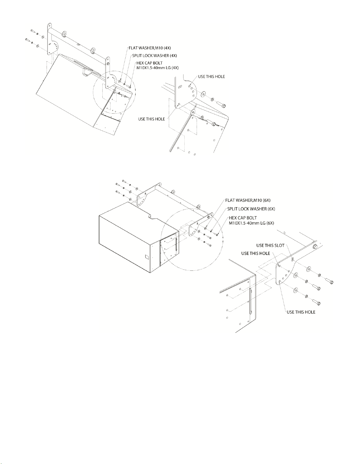
Step 9:
Position the (VLA-C-SB2) bracket’s side
mounting plate on the speaker’s mounting
holes, align holes, then secure using the
provided M10 hex bolts, split lock washers
and flat washers (Figure 11).
Step 10:
Tighten screws permanently. Reference
Torque = 30-35 ft/lb
Step 11:
0 Degrees Position
Remove and discard the existing 2 bottom
screws from the speaker’s mounting holes
where the (VLA-C-SB2) bracket will be
attached.
Step 12:
Position the bracket’s side mounting plate
on the speaker’s two bottom mounting
holes, align holes then secure
using the provided M10 hex
bolts, split lock washers and flat
washers. (Figure 12).
Step 13:
Tighten screws permanently.
Reference Torque = 35-40 ft/lb
Step 14:
Attach load rated pull back
cable to the center eyebolt of
the bracket. Slightly loosen the
end bolts holding the round
cross bar so that the crossbar
will naturally rotate axially, and
the eyebolt is in-line with the
direction of pull. Re-tigthen
bolts. Reference Torque = 45-
55 ft/lb (Figure 13).