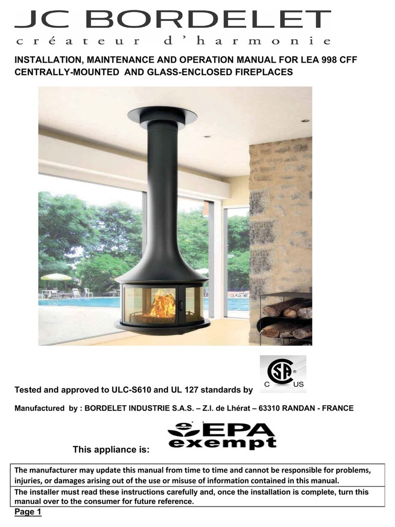
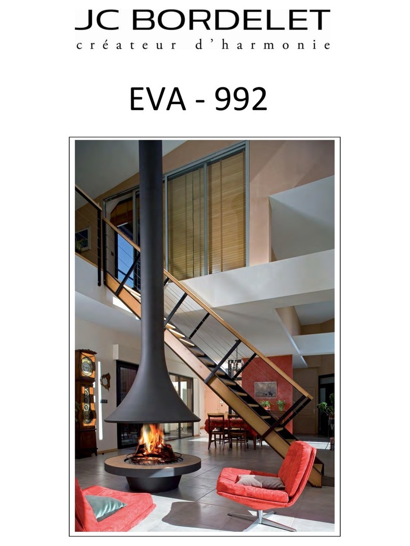
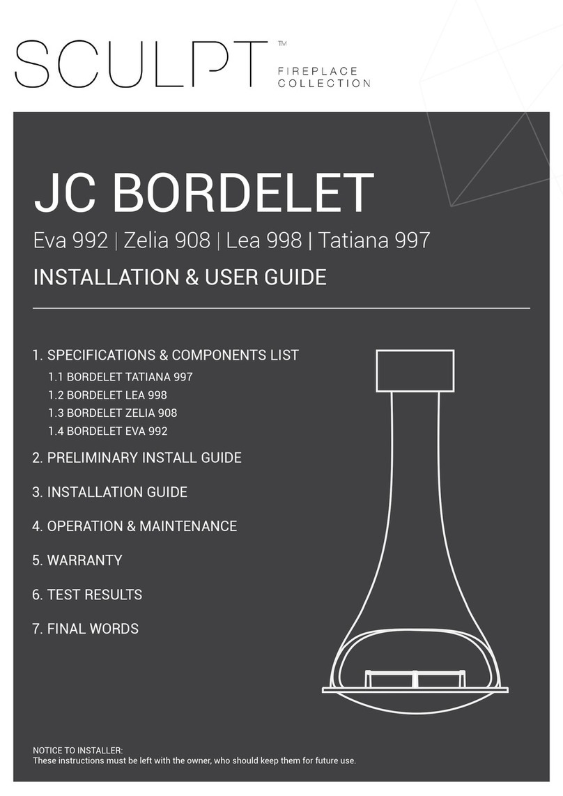
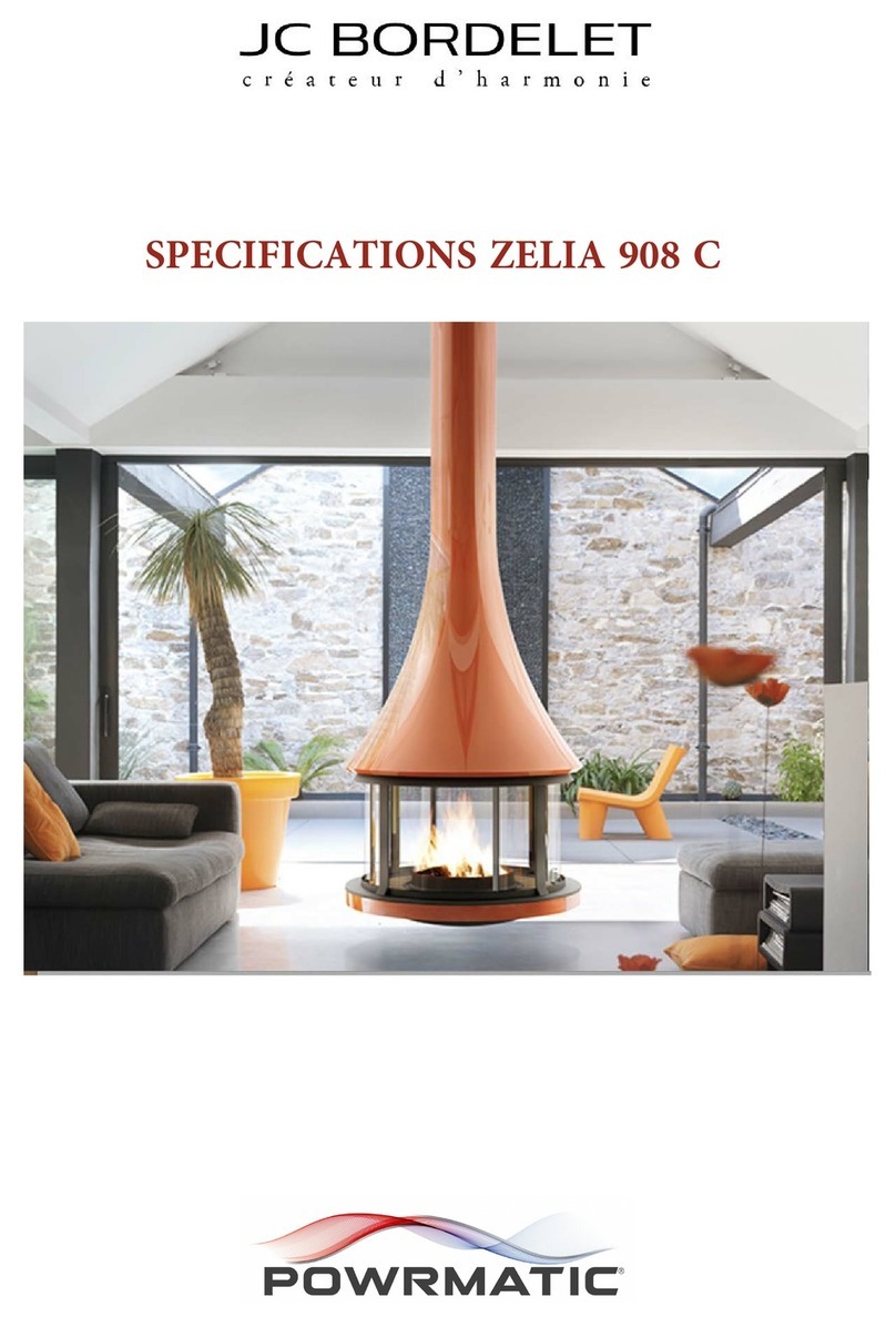
JC BORDELET Eva 992 Manual

1
1. SPECIFICATIONS & COMPONENTS LIST
2. PRELIMINARY INSTALL GUIDE
3. INSTALLATION GUIDE
4. OPERATION & MAINTENANCE
5. WARRANTY
6. TEST RESULTS
Eva 992 |Zelia 908 | Lea 998 | Tatiana 997 |
Linea 914
JC BORDELET
NOTICE TO INSTALLER:
These instructions must be left with the owner, who should keep them for future use.
1.1 BORDELET TATIANA 997
1.2 BORDELET LEA 998
1.3 BORDELET ZELIA 908
1.4 BORDELET EVA 992
1.5 BORDELET LINEA 914

3
2
COMPLIANCE PLATE AND SERIAL NUMBER.
Thank you for choosing Sculpt Fireplaces as your heater of choice.
Your replace is the result of careful design, artisan engineering and safety tests.
If it is properly installed, used and maintained, you may be sure that you will have an outstanding
heating feature in your home for years to come.
We advise you to read through this guide in order to become acquainted with the installation
methods specic to your replace.
It is recommended that this replace be installed by a qualied and licensed trades professional.
You will nd in this guide the answers to most of your questions, should you require further
assistance we recommend you contact your retailer.
Before igniting your replace for the rst time, please carefully read this manual.
Follow @sculptreplacecollection on Instagram, SculptFireplaceCollection on Facebook and be
sure to post your latest masterpiece installed with the hashtag #sculptres.
We hope we’ve helped make you the envy of your friends this winter and for years to come.
From all of us,
Sculpt Fireplace Collectionion
CONGRATULATIONS!
IMPORTANT
Heating capacity of the following appliances are a guide only and refers to areas with 2.4m ceilings
and 6 or more star rated buildings. Heating output may vary depending on factors such as building
characteristics, quality of insulation and type of rewood used and climate zone.
All dimensions shown are approximate. Check all dimensions accurately prior to installation. In line with
our policy of continuous improvement, we reserve the right to alter specications without notice.
All units comply and MUST be installed to Australian & New Zealand Standard AS/NZS 2918:2001.
When in use some parts may become hot, a suitable re guard is recommended where very young,
elderly or inrm are concerned.
THE BORDELET UNITS IN THIS MANUAL CONFORM TO AUSTRALIAN AND NEW ZEALAND STANDARDS
AS/NZS 2918:2001 DOMESTIC SOLID FUEL BURNING APPLIANCES & AS/NZS 4012/4013(2014).
The instructions in this manual are recommendations only, the distributor and manufacturer bears no liability to the interpretation of these instructions.
© Copyright 2019 Sculpt Fireplaces Collection

5
4
400mm
1.1 SPECIFICATIONS & COMPONENTS TATIANA 997
CEILING
1.1 SPECIFICATIONS & COMPONENTS TATIANA 997
material
hearth dimensions
clearances to combustibles
includes
fireplace weight
triple skin flue sizes
minimum flue height
bearing flame
& dropper box weight
1. bearing plate & dropper box
2. ceiling cover plate
3. additional pipe (optional lengths)
4. the fireplace
5. ash grate
4mm thick spun steel
Minimum 1770mm diameter X 40mm thick
Minimum 750mm
Fire grate
120kg
240mm, 290mm, 340mm
4.5m
50kg
Tatiana 997
ADJUSTABLE
2438mm
650mm 310mm
236.5m
620mm
980mm
min 150mm
2.
Tatiana 997
1.
1.
3.
4.
5.
2440mm
236.5mm
150mm
450mm
980mm
310mm
620mm
NON-COMBUSTIBLE FLOOR

7
6
1.2 SPECIFICATIONS & COMPONENTS LEA 998
450mm
400mm
150mm min
213mm
700mm
2438mm
CEILING
1.2 SPECIFICATIONS & COMPONENTS LEA 998
Lea 998
ADJUSTABLE
Lea 998
1. bearing plate & dropper box
2. ceiling cover plate
3. additional pipe (optional lengths)
4. the fireplace
5. the baffle
6. ash pan
7. ash grate
8. glass panels
150mm
212.7mm
440mm
700mm
450mm
420mm
2440mm
material
hearth dimensions
clearances to combustibles
includes
fireplace weight
triple skin flue sizes
minimum flue height
bearing flame
& dropper box weight
4mm thick spun steel with safety glass
Minimum 1300mm diameter X 40mm thick
Minimum 500mm
Fire grate and ash pan
130kg
215mm, 265mm, 315mm
4.5m
50kg
2.
1.
4.
5.
1.
3.
6.
8.
7.
NON-COMBUSTIBLE FLOOR
350mm

9
8
1.3 SPECIFICATIONS & COMPONENTS ZELIA 9081.3 SPECIFICATIONS & COMPONENTS ZELIA 908
CEILING
Zelia 908
ADJUSTABLE
450mm 420mm
480mm
980mm
236.5mm
2438mm
min 150mm
material
hearth dimensions
clearances to combustibles
includes
fireplace weight
triple skin flue sizes
minimum flue height
bearing flame
& dropper box weight
4mm thick spun steel with safety glass
Minimum 1770mm diameter X 40mm thick
Minimum 750mm
Fire grate and ash pan
150kg
240mm, 290mm, 340mm
4.5m
50kg
150mm
236.5mm
2440mm
480mm
420mm450mm
980mm
2.
5.
8.
1.
6. 7.
3.
4.
Zelia 908
1. bearing plate & dropper box
2. ceiling cover plate
3. additional pipe (optional lengths)
4. the fireplace
5. the baffle
6. sliding glass & fixed glass (x2)
7. ash pan
8. ash grate
NON-COMBUSTIBLE FLOOR
400mm

11
10
1.4 SPECIFICATIONS & COMPONENTS EVA 992
2438mm
360mm
460mm
620mm
1170mm
265mm
150mm min
CEILING
ADJUSTABLE
1.4 SPECIFICATIONS & COMPONENTS EVA 992
Eva 992
150mm
minimum
265mm
2650mm
1170mm
575mm
360mm
460mm
material
hearth dimensions
clearances to combustibles
includes
fireplace weight
triple skin flue sizes
minimum flue height
bearing flame
& dropper box weight
4mm thick spun steel with safety glass
Minimum 1770mm diameter X 40mm thick
Minmum 750mm
Fire grate and ash pan
200kg
265mm, 315mm, 365mm
4.5m
50kg
1. bearing plate & dropper box
2. ceiling cover plate
3. additional pipe (optional lengths)
4. the fireplace
5. the baffle
6. sliding glass & fixed glass (x2)
7. metallic ring
8. the base
9. shutter (x2)
10. ash pan
11. ash grate
place the two caps on either side of the base, if
an outside air kit is installed under the floor.
put in place the metallic ring to hide screws.
1.
2.
3.
4.
5.
8.
9.
6.
7.
10.
11.
NON-COMBUSTIBLE FLOOR
Eva 992
400mm

13
12
150mm
minimum
400mm
244mm
1.5 SPECIFICATIONS & COMPONENTS LINEA 914
2438mm
CEILING
ADJUSTABLE
Linea 914
2400mm
material
hearth dimensions
clearances to combustibles
includes
fireplace weight
triple skin flue sizes
minimum flue height
bearing flame
& dropper box weight
4mm thick spun steel with safety glass
Minimum 1300mm diameter X 40mm thick
850mm
Fire grate and ash pan
130kg
240mm, 290mm, 340mm
4.5m
50kg
NON-COMBUSTIBLE FLOOR
1.4 SPECIFICATIONS & COMPONENTS LINEA 914
1. bearing plate & dropper box
2. ceiling cover plate
3. additional pipe (optional lengths)
4. the fireplace
5. the baffle
6. sliding glass & fixed glass (x2)
7. metallic ring
8. the base
9. ash pan
10. ash grate
place the two caps on either side of the base, if
an outside air kit is installed under the floor.
put in place the metallic ring to hide screws.
700mm
620m
575mm
360m
470mm
200mm
1120mm
Linea 914

15
14
2. PRELIMINARY INSTALL GUIDE 2. PRELIMINARY INSTALL GUIDE
It is the users duty to make themselves aware of and apply all national or more restrictive local
standards and instructions (AS/NZS 2918:2018).
IMPORTANT
Prior to unpacking and installation ensure the appliance has not been damaged during transit. Please
ensure you check the glass/door, the air flow damper controls and the door locking mechanism where
applicable.
Before any work is carried out, as per local and national regulations and laws, this appliance MUST be
installed by a licensed professional as per and AS/NZS 2918:2018.
IMPORTANT WARNING
It is strictly forbidden to use any combustible materials (ie; wooden framing, plaster, etc) near or around
this appliance. Any exception from this rule is a health and safety hazard which will result in a non-
compliant installation and a void of warranties.
Electrical cables and components must not be placed in the vicinity of the appliance as it is a re
hazard.
For the installation and use of this appliance, the tter and the user should strictly adhere to local and
national regulations in addition to AS/NZS 2918:2018. The installer should comply with the instructions
and recommendations detailed in this manual. The safety and operation of the replace is directly
dependent thereon. The liability of the manufacturer or distributor can neither be retained nor assured
following failure of installation or incorrect use which does not comply with AS/NZS 2918:2018.
As each installation is unique, a qualied and licensed trades professional should take all required
preliminary precautions depending on the technical elements inherent to each job.
In-observance of the assembly instructions in conjunction with AS/NZS 2918:2018 entails the liability
of the person who carries it out.
As a result of faulty assembly, irrational use of parts or additional components that were not supplied
by the manufacturer, and/or modifying of the appliance or components will result in inferior or unsafe
operation. Should this occur the manufacturer bears no liability, and will result in a null and void product
warranty.
PRELIMINARY INSTALL INFORMATION
All images and diagrams in this manual are for installation reference purposes only and are not to
scale, the distributor and manufacturer bears no accuracy of these images and accepts no liability. The
purpose of these images and diagrams is to act as a guide in conjunction with the written components,
and are NOT to be used to instruct independently. The order of steps listed in this manual are
recommendation only.
It is strongly recommended that the licensed trade professional who is performing the installation of
this appliance, completely read and comprehend all instructions in this manual prior to proceeding.
Sculpt Fireplaces & Bordelet reserves the right to change these specications without prior notice.
ACCEPTABLE VARIANCE ALLOWANCE
Due to the production of these hand crafted and manufactured replaces, there is an acceptable
allowance of 3-5mm variance of the unit, including the door frame (if applicable). This variance in
production is non-claimable under any warranties.
HEAT RESISTANT MATERIALS
Heat resistant materials must meet AS/NZS 2918:2018 clause 1:4.27 a material with an allowable
service temperature of 600° Celsius or greater.
PLEASE READ PRIOR TO INSTALL

17
16
3. INSTALLATION GUIDE3. INSTALLATION GUIDE
Determine the exact location of the bearing frame and the dropper box above the ceiling in accordance
with the proposed location of the; LEA 998, TATIANA 997 and ZELIA 908 will be centred in the room and
hang a minimum of 450mm above the hearth(non-combustible floor). The EVA 992 and LINEA 914 will
be centred in the room below and the lowest edge of the replace hood will be 820mm above the hearth.
Beams in the roof may need to be altered to suit the Bordelet bearing frame and dropper box.
For reasons of shipping and handling, all our replaces are delivered in separate components and
require assembly.
Assembly should be carried out according to this manual which should be read in it’s entirety prior to
commencing installation. Any in-observance of the assembly instructions entails the liability of the
licensed trade professional who carries it out. IMPORTANT: When connected to the bearing frame, the dropper box must sit a minimum 150mm below
the ceiling.
1. INSTALLING THE BEARING FRAME AND THE DROPPER BOX
ASSEMBLING THE FIREPLACE
FLAT ROOF INSTALLATION OF BORDELET
DROPPER BOX ONTO BEARING PLATE.
PITCHED ROOF INSTALLATION OF
BORDELET DROPPER BOX ONTO
BEARING PLATE.
BOLT
DROPPER
BOX &
BEARING
FRAME
USING
BOLTS PER
SIDE.
BOLT DROPPER BOX & BEARING
BEARING PLATE
BEARING PLATE
150MM
MINIMUM
CEILING
CEILING
FLAT ROOF INSTALLATION PITCHED ROOF INSTALLATION
BASE (IF APPLICABLE)
HOOD
MINIMUM 1000MM
NON-COMBUSTIBLE HEARTH
ROOF
CAVITY
TRIPLE SKIN
FLUE
DROPPER BOX AND
FIXING PLATE
CEILING
MINIMUM 3000MM
DIAMETER CLEARANCE
MINIMUM 150MM
FROM CEILING
BORDELET EVA 992 DIAGRAM USED
MINIMUM 600MM

19
18
3. INSTALLATION GUIDE
If the TATIANA 997, ZELIA 908 and LEA 998, reach a height of more than 4 meters from floor to ceiling
then an Anti-Sway bracket must be installed to stabilize the installation and prevent oscillations which
might, in the long run, loosen fasteners.
If the EVA 992 and LINEA 914 reaches a height of more than 5 meters from floor to ceiling then an Anti-
Sway bracket is highly recommended.
Centred on the planned location of the replace, install a hearth made of approved non-combustible
material such as ceramic tiles, stone, masonry or concrete etc.
4. INSTALLING THE HEARTH NON-COMBUSTIBLE
7. INSTALLING ANTI-SWAY BRACKET
For added height (floor to ceiling), install the additional pipes (if required), onto the dropper box (using
the 3 screws TF M8x16).
Air intake is essential for the proper operation of the appliance, if installed in a well insulated/ 6 or
more star rated home. The air intake should be located in an area vented to the outdoors or in an area
exposed to non de-pressurised prevailing winds.
The air intake outlet should be located either directly in the chimney, or as close as possible to the
appliance. The air intake should be vermin proof.
MINIMUM FRESH AIR INTAKE
EVA 992, LINEA 914 AND TATIANA 997
• 300cm2
LEA 998 AND ZELIA 908
• 200m2
The connecting flue should not include more than two 45° offsets (i.e. more
than one non-vertical portion), the angle of these offsets should not exceed
45° with the vertical.
IMPORTANT: When a controlled mechanical ventilation includes an electric
extractor, it is absolutely necessary to stop operation of the replace. The
electric extractors of the kitchen, the bathroom, or the toilets, should also be
switched off when operating the replace.
LEA 998, ZELIA 908 AND TATIANA 997
Install the LEA 998, TATIANA 997 and ZELIA 908 onto the dropper box (or the additional pipe if
requested) with the lower shelf of the replace 450 mm above the nished hearth.
INSTALLING THE FIREPLACE
5. INSTALLING THE INTERNAL COMPONENTS
2. INSTALLING THE ADDITIONAL PIPES 6. AIR INTAKE
3. 45° OFFSETS OF CONNECTING FLUES
EVA 992 AND LINEA 914
Install the EVA 992 and LINEA 914 canopy onto the dropper box (or the additional pipe if required) with
the lower edge of the replace hood 820mm above the nished hearth. Make sure that all the fasteners
are tight. Centre the base of the EVA 992 and LINEA 914 on the non-combustible hearth in perfect
vertical alignment with the hood and bolt it down making sure that the exact 460mm clearance between
the canopy and the base is maintained.
TATIANA 997, LEA 998 and ZELIA 908
Install the baffle plate ensuring the flat surface is positioned upwards, proceed to gently position the
plate on the lugs located on the inside of the replace. Once in position ensure the plate sits securely,
the baffle plate should not rock or shift when touched if placed correctly. Install the ash pan and the ash
grate on the base of the replace, it should be noted an ash pan and baffle pleate is NOT supplied with
the TATIANA 997.
EVA 992 AND LINEA 914
Install the baffle plate ensuring the flat surface is positioned upwards, proceed to gently position the
plate on the lugs located on the inside of the replace. Once in position ensure the plate sits securely,
the baffle plate should not rock or shift when touched if placed correctly. Install the ash pan and the ash
grate on the base of the replace. Install the ring screw caps at the bottom of the base if necessary.
Install the 2 shutters at the bottom of the base, in case the replace is not connected to an air intake
from the floor.
3. INSTALLATION GUIDE
TYPE 1: WALL BRACKET
TYPE 2: CENTRAL BELT BRACKET WITH CABLE TIES
TYPES OF ANTI SWAY BRACKETS
MINIMUM
300MM FLUE
ANTI-SWAY BRACKET REQUIRED OPTION FOR 4000MM
HIGH(OR MORE) INSTALLATIONS
ADJUSTABLE
FASTENED BY SCREWS
TIGHTENING SCREWS
TIGHTENING NUTS
21
20
INSTALLING ZELIA 908, EVA 992, AND LINEA 914 SAFETY GLASS PANELS
MOUNTING OF THE FIXED GLASS
1. Insert the glass (7) by the central part of the replace, then slide until it ts into location.
2. Place 2 legs (2) and joints (3), then tighten the screws (1).
3. Place the 2 legs (5) and joints (6), then tighten the screws (4).
MOUNTING OF THE MOBILE GLASS
1. Remove the removable plate (9) by unscrewing the screws (8).
2. Place the sliding glass (10) in the rails.
3. Replace the removable plate (9) and tighten the screws (8).
3. INSTALLATION GUIDE 4. OPERATION & MAINTENANCE
OPERATION & USER GUIDE
IGNITION INSTRUCTIONS
Before any ignition ensure the primary air is open in order to accelerate combustion and evacuate the
fumes. This adjustment should then be reduced as the re has stabilised in order to maintain a longer re
term and avoid any possible overheating. The door of the replace should be closed in order to avoid any
risk of back-flow.
Always slowly and gradually light the re; split wood and re starters are recommended. It is strictly
forbidden to use any volatile substances including; methylated spirits, gasoline, solvents or the likes as
these will result in a risk of explosion or thermal shocks by a sudden rise of temperature.
OPERATING THE WOOD BURNER WITH THE DOOR OPEN EXPOSES YOU TO MULTIPLE
HAZARDS (FALLING EMBERS, SMOKE EMISSIONS IN THE ROOM, ETC.). ALWAYS OPERATE
THE APPLIANCE WITH THE DOOR CLOSED.
PRECAUTIONS FOR THE FIRST IGNITION - CURE WITH 10 SMALL FIRES
The rst ten res should be light, moderate and not overly loaded with wood. We recommend a small re
consisting of 3-4 logs weighing around 3kg in total. Remember to open the flue damper control prior to
lighting a re.
NOTE: The flue damper must be opened while the replace is in operation. The flue damper must only be
closed when the replaces is not in operation.
PAINT
It is strongly recommended that no person(s) come into contact with the external faces of the appliance
without the protective gloves provided, this will avoid any ‘marking’ on the paint surface prior to it being
cured. The paint will polymerise after several res. Do not scrub or clean the replace with any rough
surface (such as a sponge). In the case of accidental scratches, make several res until the paint is
cured, at which time you can delicately clean the outside of the appliance with a hot sponge. Do not
scratch or rub the replace while it is lit. It is recommended contact with the replace should be kept to
a minimum. Do not paint the replace using products NOT recommended by the supplier, please contact
your authorised dealer should you require further assistance.
Avoid scratches and markings on your appliance by not placing any objects on your appliance during
operation and when not in use.
VENTILATION
A strong burning smoke odour may be smelt during the rst several res, it is therefore recommended to
ventilate the premises by opening windows/doors in order for the paint to cure. This phenomenon will
disappear after these initial burns cycles.
LIGHTING THE FIRE
The re is started with the airways open (except Tatiana 997). Open all airways to allow maximum air
intake. In order to limit smoke emission, it is preferable to use the inverted or top-down re lighting
method (see illustration below). An initial load of 3kg of wood can provide a sufcient layer of embers.

23
22
DAMPER CONTROL
When preparing the unit for use (ignition and wood loading), it is important that the damper is in the
open position. While the unit is functioning ensure the damper is in the open position. Once the re has
extinguished, close the damper.
COMBUSTION AIR SETTINGS
The combustion air control is located on the base below the replace shelf. This mechanism controls
flow of air entering the rebox, which allows for a more precise control of the re. The quantity of
combustion air entering the rebox can be altered by moving the combustion air control from the left
(low) to the right (high).
4. OPERATION & MAINTENANCE
OPEN POSITION
NOT IN USEIN USE
CLOSED POSITION
SLOW COMBUSTION
When the air combustion control is nearly closed, the replace is in its slowest combustion phase. If
the re is hot enough, slow combustion will not stop the re, but there will be a noticeable change in the
flame pattern. The flames will be slow and may appear dirty if the wood is too wet (moisture content of
15% and more). This method of operation is not recommended and will produce excessive creosote in
the replace and the flue. Creosote may also accumulate on the glass panels.
CAUTION:Continuous and intensive slow burn operation may cause early deterioration of the appliance
and it’s components, as well as a chimney re if the flue has not been regularly cleaned.
ESTABLISHING THE FIRST FIRE
Before establishing the rst re, remove all labels or equipment parts located in the ash box or in the
furnace. Open the flue damper control.
While building your rst re, keep the combustion rate at a moderate level to ensure that the sealant
binds with the paint. All materials should be seasoned.
Please note: Before building a big re, establish several res. The curing process is necessary to ensure
that the paint is not damaged and that the insert is well seasoned.
Do not overload the furnace. The optimum amount of fuel should not exceed one third of the insert
volume. Before reloading, make sure that the re has subsided. This will keep the replace from over-
ring.
Flow of air can be regulated by the primary air controls at the front of the unit.
Except for the short time required to build a re, the replace door should be fully closed. If doors are left
partly open, flue gas may be drawn out of the opening creating risks from both re and smoke.
4. OPERATION & MAINTENANCE
OPERATION & USER GUIDE (CONTINUED)OPERATION & USER GUIDE (CONTINUED)
IGNITION INSTRUCTIONS (continued)
After an extended time of non-use, it is recommended that the rebox be checked and cleaned by a
professional to ensure there is no obstruction in the flue and no blocking of the manoeuvring members
(damper) before ignition.
ACCELERATED COMBUSTION
The maximum heat output for JC Bordelet replaces is achieved with the combustion air control fully
opened. The replace can achieve an optimal heat output with two large or three medium size pieces of
wood.
MEDIUM COMBUSTION
This is the recommended mode for operating JC Bordelet replaces as it will deposit the least amount
of creosote on glass panels and in the flue. The combustion air control should be set to half-open after
ignition. The most efcient setting will vary depending on many factors including flue length and the
moisture content of the wood. Two large or three medium size pieces of wood should be burning over a
bed of hot coals.
IMPORTANT
Ventilation devices which operate with the replace on the same premises or on the premises which
share the same ventilation shaft may not function properly.
Please ensure the grate is never blocked.
During installation please allow for access to have the replace and the connecting shaft cleaned.
If required, install cut-off and stifling devices.
RECOMMENDED FUEL
This replace is designed for wood fuel only. Any fuel other than wood is strictly forbidden.
As a general rule it is recommended; use dry, well-seasoned HARD WOOD with a 15% moisture content or
less in order for the unit to burn effectively and avoid any tarring. The heating output of wood depends on
the moisture percentage.
DIRECTLY CUT
3 MONTHS
6 MONTHS
9 MONTHS
75%
48%
37%
36%
78%
62%
46%
38%
33%
18%
16%
15%
35%
27%
24%
24%
1 YEAR
1 1/2 YEAR
2 YEARS
2 1/2 YEARS
C CL L
C: Chunks L: Logs
AVERAGE WOOD DRYING TIME BASED ON MOISTURE CONTENT
NOTE: The flue damper must be opened while the replace is in operation. The flue damper must only
be closed when the replace is not in operation.

25
24
OPERATION & USER GUIDE (CONTINUED)
RECOMMENDED FUEL
If the wood is piled up loosely, it will burn faster because the necessary oxygen for the combustion will
easily reach every piece of wood. This piling is recommended if you want to heat over a short period of
time. When the wood is piled more compact, it will burn slower as the combustion air cannot reach all the
logs at the same time. This piling is recommended if you want to heat over a longer period of time.
ATMOSPHERIC CONDITIONS
Misty or foggy weather may possibly favour back-flow of the smoke, which may be a health hazard. In
this case only use the replace as is necessary.
For safety reasons, assemblies of appliances and accessories not provided or recommended by Bordelet
or Sculpt Fireplaces are NOT PERMITTED. Unsuitable equipment may affect the functionality of the
replace and can be dangerous in certain situations.
EXTINGUISHING THE FIRE
Stop fuelling the re and let it burn out. The re should burn out without any constraints. Do not close the
air slides before the re is completely extinguished, otherwise it may release noxious gases.
CAUTION: Do not hang or install objects within 2m of the appliance. This includes paintings, photos,
televisions, and any other combustible material.
IMPORTANT WARNING
Storing any flammable materials (paper, linen, furniture, solvents, flammable liquids, spray containers,
gas bottle, etc.) close to the replace is strictly forbidden.
All these products should never be stored even for a short while in wood storages or recesses laid out
under or near the appliance.
CAUTION: The window, the front panel of the appliance, as well as all external faces including the
facade, will attain high temperatures (above 100°C). Uninitiated persons, young children and infants
should be monitored at all times while in the vicinity of the appliance.
TRANSITION PERIOD, INSUFFICIENT CHIMNEY DRAUGHT AND POOR WEATHER CONDITIONS
Pay attention to the operations of the insert during transition periods and/or when chimney draught is
insufcient or when weather conditions are unfavourable, especially during severe cold weather. Such
conditions may cause flue gas to flow into the room. To prevent such a situation, you should reduce
the intensity of re by curbing the influx of air into the combustion chamber until smoke disappears.
Afterwards you may increase air flow monitoring for any appearance of smoke in the room.
MAINTENANCE
Before the rst res in autumn we strongly recommend cleaning the top of the appliance to prevent
carbonising the dust that could then be deposited on the convection grate.
CLEANING THE GLASS
The window of the replace requires regular cleaning with specic products intended for this use. The use
of moist hard wood with a moisture content above 15% causes excessive creosote build up on the glass.
Once again we recommend only burning very dry hard wood.
MAINTENANCE (CONTINUED)
CLEANING THE GLASS (CONTINUED)
We recommend waiting for the glass to cool before cleaning it. The use of products that are too aggressive
(eg. abbrasive cleaners) may lead to the deterioration of some of the wood heater parts. An effective and
ecological method of cleaning the glass is to use a piece of damp newspaper dipped in ash and then
rinsing with clean water. You can also use a commercially available glass cleaning product.
FLUE & FIREBOX
Flues should be professionally cleaned and checked twice a year, including at least once during the peak
period of use and more if required. A professional should also check seals, door ropes, baffle plates and all
consumable parts of the rebox and flue to ensure the unit is in safe working order.
DO NOT REMOVE THE BAFFLE EXCEPT WHEN PERFORMING A CHIMNEY SWEEP
CAUTION: Cracked and/or broken components (eg. glass panels or baffles) may render the installation/
operation unsafe. Do not use the appliance if this is the case and contact your dealer.
ASH PAN
The ash pan should be emptied regularly in order to avoid any overflow and clogging of the re grate. You
will nd some ashes catching in the cavities between the ribs of the replate. This bed of ashes caught
between the replate is essential as it will create a more effective start up operation of the re.
FORBIDDEN FUELS
This appliance is not designed for burning the following fuels:
• Solid mineral fuels (all coals or similar)
• Liquid mineral fuels (Gasoline, fuel oil, solvents, drainage oils or similar)
• Methylated spirit
• Creosote-treated woods and too moist or green woods
• Paper or cardboard
• Wood workshop residues (Shavings, saw dusts or similar)
• Other forbidden fuels that may harm the appliance or the environment
CHIMNEY SWEEPING
It is necessary to perform a chimney sweep and ensure it’s clear of any build up (cresote, bird’s nest, etc).
Chimney sweeps should be performed twice a year, including at least once during the period of use.
CHIMNEY FIRES
Chimney res can be caused due to incorrect use of the appliance and lack of periodic cleaning.
Visible signs of a chimney re include:
• Abundant fumes
• Strong smell of soot
• Roaring in the flue
• Signicant increase in the temperatue of the flue
• Cinders flying out of the top of the flue
4. OPERATION & MAINTENANCE 4. OPERATION & MAINTENANCE
4. OPERATION & MAINTENANCE

27
26
6. TEST RESULTS
TEST REPORTS
TESTING LABORATORY
MANUFACTURER
MODEL
ISSUE DATE
INVESTIGATING OFFICER
RESULTS
CONCLUSION
HRL Technology
JC BORDELET
EVA 992 | TATIANA 997 | ZELIA 908 | LEA 998
17.11.2015 (EVA & LEA) | 18.11.2015 (ZELIA & TATIANA)
Steve Marland
The maximum carbon dioxide output of the EVA 992 / TATIANA 997
/ ZELIA 908 was performed at the high burn rate prescribed in AS/
NZS4013 (2014) gave a maximum carbon dioxide output of 3.2% (by
volume). And 2.8% (by volume) for the LEA 998.
Based on this result, exemption from testing the EVA 992 / TATIANA
997 / ZELIA 908 / LEA 998 solid fuel appliance should be claimed under
section 1.2.3 (f) of AS/NZS4013 (2014) as the maximum carbon dioxide
output from combustion is less than 5% by volume when red at the
prescribed high burn rate.
BORDELET APPLIANCE OUTPUT TEST
MAINTENANCE (CONTINUED)
Symptoms Possible cause Proposed course of action
1. Smoke comes from
the replace
2. Ash comes from
the replace
1. Air supply ventilation is choked
2. Size of chimney shaft or its length is not
sufcient
3. Fault location of chimney relevant to roof
ridge
4. No chimney cap installed
5. Improper connection of insert with
smoke shaft
6. Chimney not clear
1. Provide a clear ventilation shaft
2. Extend chimney
3. Extend chimney
4. Mount chimney cap
5. Apply reducer between replace insert
and smoke shaft
6. Call authorised specialist
Too much ash in ash box Remove ash from ash box, clear grate
3. Glass becomes dirty
4. Starting a re is a problem
or re is weak
5. Fire is too strong
6. Movable part is damaged
in use (grate, baffle board,
rear panel, side panels,
glass plate, seals)
1. Logs too thick
2. Wood too wet
3. Ash box full
4. Chimney cold
5. Air supply installation malfunctions
6. Chimney not clear
Improper rewood used (too much resin,
too wet or wood from coniferous trees) or
inadequate draught in chimney
1. Use recommended fuel
2. Use seasoned rewood
3. Remove ash from ash box, clear grate
4. Heat up chimney by burning more
paper
5. Provide or clear ventilation shaft
6. Call authorised specialist
1. Fireplace door open
2. Too strong draught in chimney
Parts subjected to normal wear and tear
need to be replaced (not covered by
warranty - see warranty terms and
conditions)
1. Close door
2. Install draught regulator
Use special cleaning agent or clean ash
from replace. If inadequate draught, see
other troubleshooting suggestions.
Buy new spares from the dealer
(dealers information can be found on the
website: https://sculptreplaces.com.au/
stockists/)
In the event of any emergency, put out the re immediately by cutting off airflow and, where neces-
sary, cover glowing wood with sand. Try to remove fuel from the hearth.
Do NOT use water to put out the re as it may cause permanent damage.
TROUBLESHOOTING AND COURSE OF ACTION TO PUT OUT THE FIREPLACE IN THE EVENT OF AN
EMERGENCY.
CHIMNEY FIRES (CONTINUED)
Suggested course of action in case of chimney res:
1. Put out the re by carefully removing the glowing logs and fully close the replace door.
2. Use a chimney sieve screen (metal mesh 2 x 10mm, preferably brass, on a 60x60cm frame).
Place the screen on the chimney top and inspect the lower parts for cracks through which re
flames may escape. A hot screen reduces the draught in the chimney and, consequently, slows
down the soot burning process.
3. If required, call the Fire Department.
NOTE: These course of actions are only recommendations. For more detailed information contact your
dealer or licensed technician
4. OPERATION & MAINTENANCE
TEST REPORTS
TESTING LABORATORY
MANUFACTURER
MODEL
ISSUE DATE
INVESTIGATING OFFICER
RESULTS
CONCLUSION
ASFT
JC BORDELET
LINEA 914
31.10.2017
Steve Marland
The maximum carbon dioxide output of the LINEA 914 was performed
at the high burn rate prescribed in AS/NZS4013 (2014) gave a maximum
carbon dioxide output of 3.2% (by volume). And 2.8% (by volume) for the
LEA 998 and EVA 992.
Based on this result, exemption from testing the LINEA 914 solid fuel
appliance should be claimed under section 1.2.3 (f) of AS/NZS4013
(2014) as the maximum carbon dioxide output from combustion is less
than 5% by volume when red at the prescribed high burn rate.
BORDELET APPLIANCE OUTPUT TEST

29
28
JC Bordelet replaces are guaranteed for 5 years. This excludes the ash pan, ash grates, re grate
retainers and baffles which are guaranteed for 1 year. Glass is not covered under any warranty.
The warranty becomes effective at the date of purchase.
WARRANTY DOES NOT COVER
1. Door seals, ropes, gaskets and glass
2. Any form of rust and/or corrosion to the painted nish of the heater
3. Salted air of a coastal region or a highly humid environment may contribute to some oxidation of
the steel, in this case the warranty is therefore not valid for damages originating from these causes
4. All defects or faults resulting from poor maintenance, inappropriate use or a non-compliant
installation which does not abide by Australian & New Zealand Standards AS/NZS 2918:2018 or
instructions are listed in this manual are not warranted
5. Any device or accessory not provided by JC Bordelet or Sculpt Fireplace Collection are strictly
forbidden and will result in a void of all warranties by the manufacturer and distributor
6. No modications can be made to the rebox or to original components supplied with the appliance
7. The manufacturer and distributor are by no means responsible for any indirect damage originating
from a handling accident
8. Cost of removal of a defective heater or re-installation of a replacement heater
9. Any glass breakage can only result from poor assembly, impact or incorrect use of the appliance.
Glass is not covered under warranty.
PERFORMANCE
The performance of our replaces are given as an indication and comparison after testing under
optimum conditions. These values reported under standard conditions may be subject to variations
if the installation and conditions of use are not equivalent to our testing conditions. In any case, the
replace remains an extra heater and should not replace a main heating system.
WARRANTY CLAIMS
Any defects / faults resulting from negligent maintenance, poor installation practices, altering or repair
of the appliance not recommended by the supplier or inappropriate use of the appliance, are excluded
from being covered under the warranty.
In the case of a faulty part, the user should immediately inform the authorised dealer.
For all warranty claims, we will require photos, proof of purchase, serial number and the date of
installation along with the compliance certicate from your licensed installer.
The guarantee is strictly limited to the exchange or repair by ourselves of parts agreed to be defective,
without exception. Costs of dismantling, assembly and transport will under no circumstance be covered
by this warranty, the manufacturer, distributor and should be handled between the user and installer.
WARRANTY
6. WARRANTY 6. WARRANTY
DATE OF PURCHASE
PLACE OF PURCHASE
DATE OF INSTALLATION
COMPLIANCE CERTIFICATE NO.
MODEL NO.
NAME AND ADDRESS OF PURCHASER
PHONE NO.
EMAIL ADDRESS
Please include a copy of your receipt and compliance certicate
WARRANTY CARD
EMAIL OR POST WARRANTY INFORMATION TO
info@sculptreplaces.com.au
PO Box, 1232 Mornington, VIC 3931
1300 851 304

31
30
7. FINAL WORDS
Intent on providing Australians with a dynamic collection of designer res, Sculpt replace collection
has strategically gathered not only award winning replace designs, but also replaces that have been
manufactured with high quality materials and the best raw steel that is built to last.
Sculpt is proud to be the sole importer of Seguin, Axis and Bordelet replaces, with exclusive distribution rights
throughout Australia and New Zealand.
Our wood re manufacturers integrate innovation, technology, environmental impact,
operational expertise and quality, whilst holding design at the forefront. We aim to ll homes
with the maximum of comfort while capturing the true art and meaning of a sculptural
replace in any living space.
Sculpt Fireplace Collection is an Australian
owned company who exclusively supply some
of world’s most sought after high-end luxury
replaces.
Whilst every effort is taken to avoid errors, SCULPT FIREPLACE COLLECTION cannot accept
responsibility for the accuracy of any statement, extract or information contained within this manual nor
can any of its contributors who have submitted material for inclusion. SCULPT FIREPLACE COLLECTION
may change or update this manual and anything described in it without notice. We will endeavour
to ensure that information, materials and data on this site are complete, accurate and up-to-date.
Information on this manual is for guidance only and cannot cover all circumstances. (E&OE)

32
1300 851 304
info@sculptreplaces.com.au Edition 15/02/2021
Other manuals for Eva 992
1
This manual suits for next models
4
Table of contents
Other JC BORDELET Indoor Fireplace manuals
Popular Indoor Fireplace manuals by other brands

Regency
Regency H2100M Owners & installation manual

Empire Comfort Systems
Empire Comfort Systems DVCT35CBN95 Homeowner's manual

Napoleon
Napoleon GDI-44N Installation and operation instructions

SIELINE
SIELINE EF42C Installation and operation instructions

Ekofires
Ekofires EKO 4010 HE Installation & user's instructions

White Mountain Hearth
White Mountain Hearth DVTL27FP90N-1 Installation instructions and owner's manual