JCM Star X User manual

1
Star X
INSTRUCTION MANUAL
JCM
®

2
CONTENTS
Introduction .......................................................................................................................... 3
Measurements & Lever Use................................................................................................. 4
Seating System Components ..............................................................................................5
Important Safety Advice ....................................................................................................... 6
Important Safety Advice -(Accessories)............................................................................... 7
Important - Chest Harness Adjustment ...............................................................................8
Important - Lap Strap Safety................................................................................................9
Adjustment Points Underneath Seat..................................................................................10
Mount and Removal of Back Legs.....................................................................................10
Head Rest Adjustment ....................................................................................................... 11
Multi Height Base - Mount & Removal ..............................................................................12
Raising & Lowering the Star on a Base ............................................................................. 13
Footplate Adjustment ......................................................................................................... 14
Adjusting Leg Length ......................................................................................................... 15
Adjusting Seat Depth ......................................................................................................... 15
Adjusting The Tilt In Space ................................................................................................ 16
Setting the Seat Supports .................................................................................................. 17
Hip Pads & Flexi Lap Strap Adjustment ............................................................................18
Back & Lateral Support Adjustment...................................................................................19
Adjusting Arm Height & Angle ........................................................................................... 20
Fitting the Tray / Operating the Brakes ..............................................................................21
Cleaning & Care.............................................................................................................22
General Maintenance.....................................................................................................22
Servicing via Approved Repairer ...................................................................................23
Service Record Log .......................................................................................................24
Warranty .........................................................................................................................25
Inspecting & Reissuing of Equipment ...........................................................................26

3
The Star X is designed to provide comfort and postural support. The system is available
in two sizes to suit children between the ages of 1 - 8 years approximately. The seating
system is not intended for those who have significant athetosis.
This instruction manual contains very important information about the Star X seating system,
how to use it safely and obtain the best results from it. Please read all the information
contained in this manual before using the chair and retain for future reference. Ensure
everyone using the equipment is aware of the contents of this manual and understands
how to use the equipment safely.
These instructions provide guidance on the adjustments for professionals, but they also
give information on how the equipment should be safely used, maintained, checked, and
correctly assembled by anyone who uses the seating system.
In every case the equipment should be supplied via qualified professionals who will have
adjusted the equipment, checked its compliance and tested it appropriately.
The seating system should only ever be adjusted by qualified professionals and persons
that are suitably trained. For further information please do not hesitate to contact us - all
contact details are on the back cover of the manual.
Thank you for purchasing our product, we
hope you enjoy your new seating system.
Introduction

4
Measurements & Lever Use
MEASUREMENTS (cm) SIZE 1 SIZE 2
MIN MAX MIN MAX
ASeat Depth 20 30 25 35
BTop of Seat to Footplate 13 30 13 35
CSeat to Top of Back 33 39 36.5 42.5
DSeat to Floor-Without Base 27 34 32 39
DSeat to Floor-5 Star Base 52 66 52 66
D Seat to Floor-Multi Height & Tilt Base 32 54 32 54
E Seat Width (between hip pads) 17.5 35.5 21 40.5
FTilt/Prone 5 Star Base 0° -25° 0° -25°
FTilt/Prone Multi Height & Tilt Base 10° -20° 10° -20°
Max user weight 40kg 60kgs
BASE FOOTPRINTS
width & length (cm) W L
Without base 36 42.5
5 Star Base 63 63
Multi Height & Tilt Base 54 72
A
C
B
D
B
C
D
EF
Base LengthBase Width
Effective Operation of Lock Levers
A
B
Never remove these levers entirely as this will prevent you
from being able to perform adjustments in the future.
To Use:
Turn the lever handle clockwise to tighten or
anti clockwise to un-tighten.
When an Obstruction is Met:
Pull the handle of the lever outwards, towards
you (A). This disables the function of the lever.
Continue to hold the lever out and reposition
the lever handle in a suitable position past the
obstruction.
Release the handle to re-engage the lever
function (B) and continue to tighten or un-
tighten in the normal way.
Repeat this procedure in areas where
adjustment is restricted due to an obstruction.
•
•
•
•
•

5
AHeadrest
BPush Handle
CBack Rest
DLateral Supports
EArm Rests
FHip Pads
GShaped Seat - Pommel Section
HFootrest
I 5 Star Base
JCastor
K Arm Angle Adjustment Lever
LHeight Adjustment Paddle for 5 Star Base
Example of Star
X without base,
mounted on
castors.
Seating System Components
A
B
C
D
E
G
F
I
H
J
K
L

6
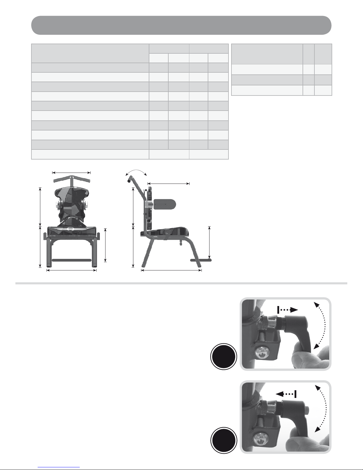
Ensure all adjustment mechanisms are secure and in place before operation. If it is
likely that the hand-wheels will be repeatedly loosened, JCM can supply allen key bolts
as an alternative. We strongly recommend this if there is a danger from those in the
vicinity of the user.
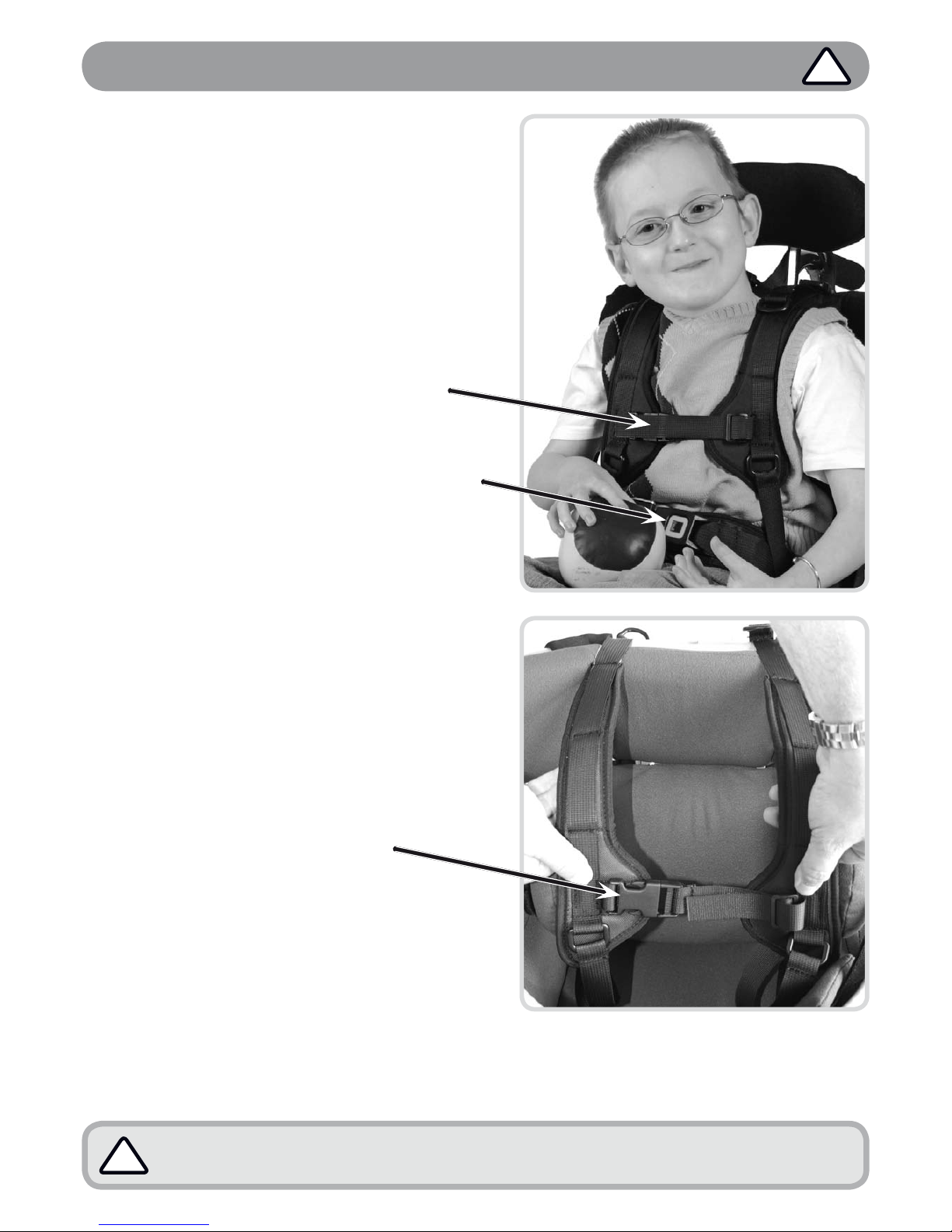
All postural support straps and harnesses should be in place and properly adjusted to
the user, prior to usage of any kind (see pages 8 & 9).
Whilst the seating system is stable on a 5-degree slope, even in its most upright position,
it is not intended to be used in this manner. It is however, intended to be used on a level
flat floor, where movement is confined to a single room. For safety ALWAYS return the
product to a neutral position before moving (lower in height, level the seat, ensure the
back is upright etc).
Heavy items on the tray will affect stability. The fitting of anything other than the standard
JCM tray may substantially affect the stability of the seating system and should therefore
be checked before issue.
If at any time it is noted that areas of the users skin remain reddened after being out of the
seating system for around 10 minutes, urgently contact the qualified professional who
performed the hand over of the equipment. This may be a sign of excessive pressure
being exerted by the seating. This might occur in the initial use of a new seat where
further adjustment may be required, where the user has been badly placed, grown or
where an underlying medical problem exists. Review may be necessary in such cases.
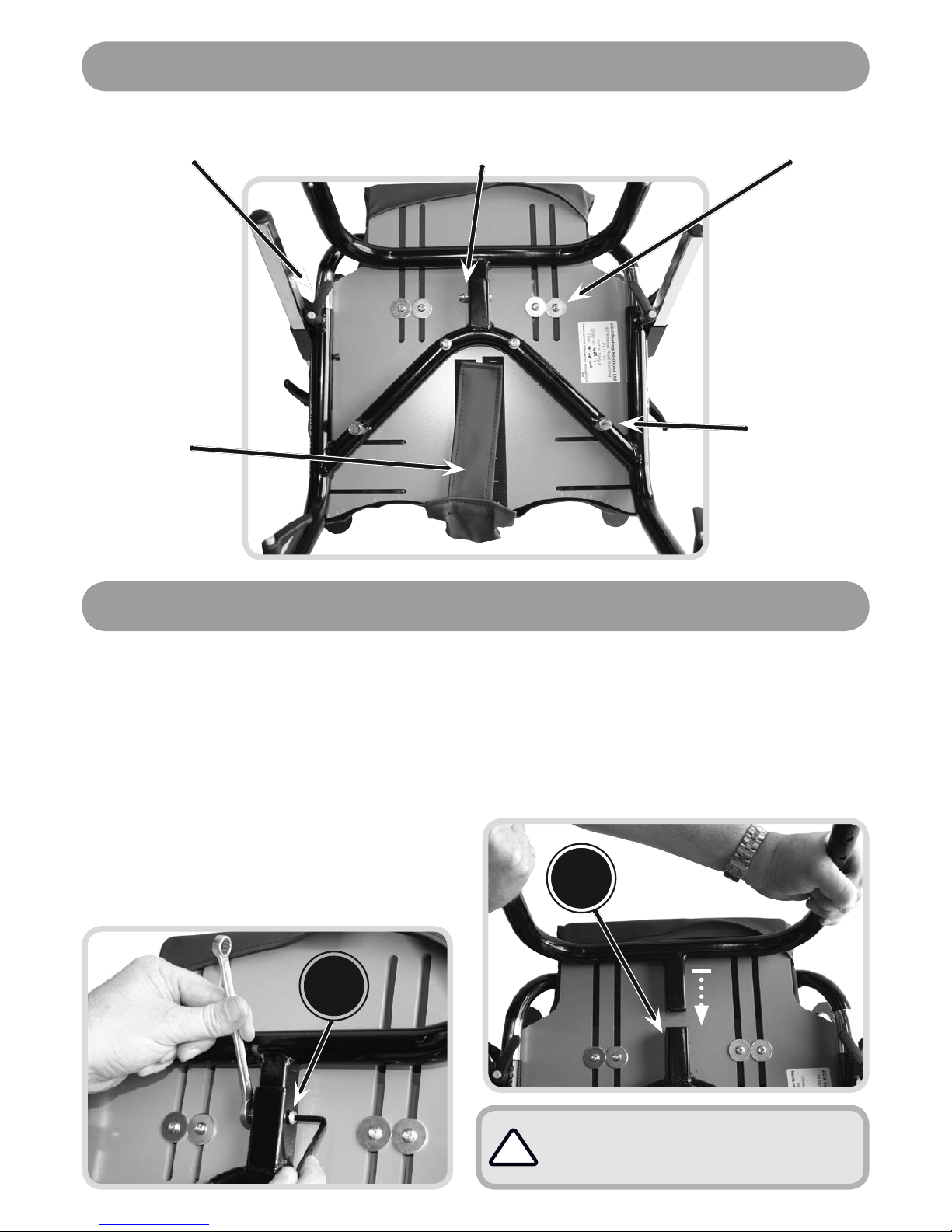
After completing any alterations ENSURE all nuts, bolts, knobs, hand wheels and other
fixings are securely tightened and in position, and that they are regularly checked as
part of the maintenance of the chair. Never over adjust or over tighten moving parts.
Keep all products away from excessive sources of heat, cigarettes and naked flames.
If you suspect that the system may be faulty, cease use of the equipment straight away
and immediately contact the organization who supplied the system. (JCMs contact
information can be found on the back cover).
The equipment will be labelled with important information. NEVER REMOVE these
information labels or allow them to be defaced, overlaid or altered.
All modifications, adjustments, reconditioning, repairs, disposal, and servicing of the
seating unit must ONLY be carried out by the agencies who supplied the equipment
(see pages 22-23).
•
•
•
•
•
•
•
•
•
•
Important Safety Advice !
We at JCM are committed to producing products of the highest standard. All of our
products fulfil the essential safety and environmental requirements as defined in
the European Directives. However, improper use of the products will potentially put
the users at risk and therefore JCM strongly suggest that the following information
is strictly adhered to at all times.
Throughout the manual there are important points to note identified by the symbol: !

7
Important Safety Advice -(Accessories)
Moore Head Support
Should only be adjusted by a therapist or competent person who understands the product
and its principals. The prongs on the head support should never be tight around the head.
Check that the prongs are NOT set near the eyes or infringe behind the ears. The foam
covering the prongs should be inspected regularly and replaced if damaged.
Multi Adjustable Head support
Wings on the head support are ideally set at 45 degrees. Do NOT bring the wings in tight to
the head. Ensure that the head support is set in such away that the child cannot loop their
head around the wings and get stuck.
Flexi-Supports and Lateral Supports
Ensure the straps do not infringe on any feeding tubes the child may have.
Pommel
The pommel is designed to abduct the users knees to help keep the hips in a good position.
Do NOT use the pommel as a way of holding the user in the seat. Remove the pommel
when transferring the user in and out of the seat (not required for Star X Series.)
Knee Blocks
Knee blocks are designed to abduct the knees and keep the hips in a good position. The
pelvis should always be well positioned and the lap strap fastened before fitting the knee
blocks. Do NOT use knee blocks without fixing the users feet with foot sandals or straps.
If the user extends in the chair this may injure the knee. Never use knee blocks unless you
are familiar with the user and know the condition of their hips. If the user has any known
medical problem, relating to their hips, consult with a therapist.
Foot Sandals and Straps
Should only be fixed when the user is wearing shoes or boots.
Tray
Do NOT use the tray as a way of securing children in a chair always ensure that the lap
strap and any other straps supplied are used. Ensure that the tray clips are secure on both
sides of the tray. If the tray is damaged, ensure that this will not be a hazard to the user.
Never leave hot items on the tray while children are unattended.
!

8
If there is any possible chance of the child getting the straps caught around
their neck, REMOVE THE HARNESS IMMEDIATELY.
!
Important - Chest Harness Adjustment
GREAT CARE should be taken when fitting
a chest harness and the following points
should always be followed:
The straps on the harness should never
be allowed to move close to or in any way
cause an obstruction to the childs neck.
The straps should never be fitted too tightly
and should be clear from any obstruction.
The cross strap on the chest harness
should always be adjusted prior to use
to ensure that it is no higher than the
middle of the users chest.
A lap strap should always be fitted if a
harness is being used to ensure the child
cannot slide down onto the cross strap.
Always ensure that the belts offer your
child both comfort and support. If the
childs clothing has been adjusted (i.e. a
jumper removed) the straps should be re-
adjusted accordingly.
Fixing Onto Chair
The straps at the top of the harness should be
attached to the back frame of the chair. The
straps at the bottom of the harness should be
attached to the back of the seat frame.
Fastening of Belts
Feed the fabric belt through the
buckle on the strap.
The belts should be pulled through
enough to suitably support your
child whilst still being comfortable.
When this has been achieved the
buckle should be snapped closed
to secure the strap in place.
•
•
•
•
•
•
•
•
!
The same precautions highlighted here should be adhered to when using any form of
trunk supports or flexi supports with straps.

9
Important - Lap Strap Safety
Incorrect fitting of lap straps can put the user at serious risk. When using lap
straps we recommend the following points should always be adhered to:
Lap straps must always be fitted at 45 degrees to the pelvis of the user.
Always check that the child’s pelvis is symmetrical and positioned securely at the back
of the seat.
Always ensure that the lap straps and chest harness hold the child securely and are
comfortable. Ensure they provide a snug fit, a simple rule of thumb is to allow two
fingers to be inserted between the belt and the childs body.
Never leave a child in a chair unattended without the lap strap being fastened.
A lap strap should always be fitted if a harness is being used.
When altering the angle between the seat and the back of the chair always re-adjust
the chest harness and lap strap accordingly to ensure all safety recommendations are
followed.
Harness and Lap Strap Positioning
This diagram shows the recommended positioning of the chest harness and lap straps:
•
•
•
•
•
•
!
Chest
Harness
Fitting
Lap Strap
Fitting
Lap Strap
Fitting
The cross
strap on the
chest harness
must be fitted
no higher than
the sternum
(mid chest).
All straps &
harnesses
must be
securely
fitted to the
back of the
chair.
Second
fixing for
four-point
lap strap

10
Always ensure that the legs are
securely fastened onto the seat
frame before using the chair.
!
Mount and Removal of Back Legs
Removal of the Back Legs
To perform this operation place the chair
upside down to allow easier access to the
adjustment area. You should use a 10mm
spanner and a 4mm allen key for this
procedure.
Loosen the screws (A) located either
side of bar, with the allen key, (using the
spanner if needed). Once loose, the legs
are ready to be removed.
Slide the legs away from the frame.
•
•
Remounting of Legs
Reversetheremovaloperation,slottingthe
backlegsinto thebaron the seatframe(B).
Securely tighten bolts (A) with the allen
key and spanner ensuring that the legs
are held firmly in place.
•
•
A
B
Adjustment Points Underneath Seat
Back leg
fixing point
Hip pad
adjustment points
Seat depth
adjustment levers
Fixing pins
(used for
mounting to
base)
Seat cover
attachment

11
Head Rest Adjustment
A
B
Adjusting the Headrest Height
Lever (B) is used to position and
lock the headrest at the required
height to suit your child. Loosen this
lever by turning it anti-clockwise.
Manually position the head rest into
the desired vertical position.
When a position of comfort and
support is found, the head rest
should be secured in place
by tightening the lever, turning
clockwise until suitably fixed.
•
•
•
Adjusting the Head Rest Position
Levers (A) should be operated
together to achieve the desired head
positioning of the user. Loosen the
levers by turning anti-clockwise.
Once loose, the head support
angle, vertical and horizontal
position can all be manually
adjusted to suit your child.
When the desired position has
been achieved the head support
should be locked into place by
tightening both of the levers,
turning them clockwise until secure.
Levers (A) can also be used
together to remove the headrest
and completely turn it around to
offer a greater range of adjustment.
•
•
•
•

12
Always check that the levers are securely locked back into place to avoid
the possibility of the Star chair becoming loose from the multi height base.
!
Multi Height Base - Mount & Removal
It is recommended that the chair is positioned on a level surface to
perform this operation.
Removal of Chair from the
Multi Height Base
(A) highlights the lever which is used
to locate the chair on its multi height
base. (There is one lever on each
side of the frame which locks onto the
location pins in the seat frame).
To remove the chair from its
base both levers (A) should
be untightened to free the
seat pins (C).
Once the levers have
been untightened the
chair should be free to be
removed from its base.
Vertically lift the seat frame up
and away from the base.
•
•
•
A
B
Replacing the Seat onto the Multi Height Base
Once again ensure levers (A) are untightened. Lower the chair, lining the protruding
steel seat pins (C) with the location holes on the base frame. (B) highlights the location
hole (duplicated on the other side of the chair.)
The pins should easily slide into the location holes and ensure a secure fit between the
two components.
Once the seat has been located on the base the user should tighten levers (A) to secure
the pins in place.
•
•
•
C
Never attempt this operation with the user seated in the chair.
!

13
Raising & Lowering the Star on a Base
Raising & Lowering - Multi Height Base
Paddle (A) enables you to raise or lower the chair whilst on its multi height base.
Gently press the pedal and pull or push the chair to the desired height, releasing the
pedal to lock.
Please note that the chair is designed to adjust while a user is sitting in the chair. If you
need to adjust height down, without the user in the seat, you may need assistance
pushing down on the seat.
The pedal does not need excessive force to activate the mechanism.
•
•
•
Raising & Lowering - 5 Star Base
Hinge paddle (B) vertically up towards
the seat to release the mechanism
and raise the chair - it may be
necessary to assist the lift manually if
there is weight in the chair.
To lower the chair simply hinge the
paddle up as before and push the
chair manually down, releasing the
paddle when the desired position has
been found. If weight is loaded to the
chair it will not be necessary to assist
when lowering.
The chair can be secured in any
position within this range to suit the
user and activity.
•
•
•
A
B

14
Footplate Adjustment
A
Adjusting Footplate Height
Levers (A) allow the operator to
position the footplate and cater
for the leg length of the user.
Loosen levers (A) by turning
them anti-clockwise.
Manually slide the footplate up
and down the legs.
Once a suitable position has
been acquired, lock into place
by re-tightening the levers.
Adjusting Footplate Angle
The angle the footplate sits at when
in use can be set using bolt (B).
Simply screw the bolt (using
an allen key) clockwise or anti-
clockwise to raise or lower the
footplate.
The footplate will remain in the set
position until further adjustment.
Never remove the bolt entirely as
this will stop you from being able
to set the angle of the footplate.
Flip-Away Footplate Motion
To flip the footplate away when
transferring the child to the chair.
Hinge the footplate upwards (C)
with your hands until it stays in the
vertical position.
When the footplate is once again
required you should gently ease it
back down into position.
•
•
•
•
•
•
•
•C
B

15
Adjusting Leg Length
The leg length of your Star X can be
adjusted by 4 inches to provide a
height allowance when the chair is
used without a multi height base or if
you wish to lower the footplate for a
user with longer legs.
To lengthen: press button (A) into
the frame, this should unlock the
leg in its frame and allow you to
slide the leg up or down within its
chamber.
Their are four holes (B) which act as
locator for the leg and you should
ensure that the leg button has
securely located into the desired
hole before operating the chair.
•
•
It is possible to adjust the
seat depth of your chair by
simply extending the back
outwards to maximise the
seat board available.
Loosen both levers (A)
(there is one either side of
the chair).
Slide the seat along the
frame by pulling equally
from the rear of the back
seat section.
When a suitable seat
depth has been acquired
the back should be
locked into position by
tightening the levers
(turning clockwise).
•
•
•
Adjusting Seat Depth
A
A
B

16
Adjusting Tilt Position - Multi Height Base
The Star X offers a range of tilt when the chair is located upon its multi height base. Always
ensure that the weight of the chair and the user are supported when adjusting the tilt.
The chair can be operated at any point within the tilt range and the arms can be adjusted
to provide suitable tray positioning. The chair can be tilted to 30 degrees recline to assist
with positioning and support. To adjust the tilt:
Depress lever (A)
and manually tilt
the chair to the
desired position
whilst supporting
the chair by the
handle at the top.
Once a suitable
position of tilt has
been achieved,
release the lever
to lock the seat
into place.
•
•
Adjusting The Tilt In Space
A
Adjusting Tilt Position -
5 Star Base
Loosen lock lever (B) by turning
anti-clockwise.
Tilt the chair into the desired
position.
Securely tighten the lock lever
(B) by turning clockwise.
•
•
•
B

17
Abduction Pads
Pull back the seat cover (it is attached with velcro to the underside of the seat) to
reveal the supports beneath.
Adjust the abduction pads (A), by simply lifting them up from the velcro fastening and
repositioning them in the desired location to give enhanced comfort and support.
Built-in Pommel
(Bolts (B) are found directly beneath the pommel on the underside of the seat)
Loosen the two bolts (B) by turning them anti-clockwise using the allen key provided.
Reposition the pommel in the desired location to provide comfort and support to the user.
Finally secure the pommel in place by tightening the bolts.
•
•
•
•
•
A
Setting the Seat Supports
B

18
Upon adjustment NEVER remove the bolts entirely.
!
Hip Pads & Flexi Lap Strap Adjustment
Adjusting the Position of the Hip Pads
Loosen the two bolts (A) on the underside of the seat by turning them anti-clockwise
using the allen key provided. Do not remove bolts entirely.
When the bolts are suitably loose the hip pads (B) are free to be manually moved into
position.
When the pads are suitably supporting the user simply re-tighten bolts (A) to secure
the pads in place.
•
•
•
A
Adjusting the Flexible Lap
Straps
(C) highlights the plastic clip used to
adjust and lock the flexible lateral strap
into position. Pull open the clip and
feed the fabric belt through the buckle.
The belt should be pulled through
enough to suitably support your child,
when this has been achieved the
buckle should be snapped closed to
secure the belt into position.
•
•
View from underneath chair at the bottom
of the hip pads.
C
B

19
Adjusting Height & Width of Lateral Supports
Adjusting the Height of
the Back Support
Levers (C) are used to adjust
the height position of the back
support. This adjustment is
provided to cater for growth in
the child and allows for 100mm
of adjustment.
Loosen both levers (C) by
turning them gently in the anti-
clockwise direction (do not
remove the levers entirely.)
Once loose the back can be
manually adjusted to the desired
position by lifting or lowering it
within the slots provided (D).
Lock the back into place by re-
tightening levers (C), (turning
clockwise).
•
•
•
Turn both hand wheels (A)
anti-clockwise, enough to
allow for free movement.
Adjust the lateral supports
vertically or horizontally
until the required position
has been achieved,
enabling the user to sit in
a position offering both
comfort and support.
Lock the supports into
place by re-tightening
the hand wheels (turning
clockwise).
•
•
•
Additional Strapping
(B) - This slot has been provided
to allow for additional strapping
to be used if required.
Back & Lateral Support Adjustment
A
C
D
B

20
Adjusting Arm Height & Angle
A
Adjusting Arm Height
(A) highlights the lever which is used to adjust the height of the arms and therefore in turn
the height of the tray.
Loosen lever (A) by
turning it in an anti-
clockwise direction, this
will enable the arm to
be manually slid up or
down within its location
bracket.
When a suitable
position has been
acquired, lock the arm
into place by tightening
the lever, turning in the
clockwise direction.
Adjusting Arm Angle
The arms fitted to your Star X chair can be altered to sit throughout an angle range, enabling
the user to level their tray no matter what tilt the chair is secured at.
Loosen lever (B) by
turning it anti-clockwise.
Once loose, the arm
can be manually
adjusted throughout
a range of angles to a
suitable position and
then locked off.
When the desired
location has been
acquired tighten
the lever by turning
clockwise.
•
•
•
•
•
B
Always ensure that the arms of the chair are secure.
!
Table of contents