Jean Lebeniste MC1100B User manual

MODEL MC1100B
VARIABLE SPEED
WOOD LATHE
INSTRUCTION MANUAL
Please read and fully understand the instructions in this manual
before operation. Keep this manual safe for future reference.
Version: 2015.02.02

1
TECHNICAL DATA
Model number………………………………………………...………………………………………………… MC1100B
Speeds………………………………………………...…………………………..…………………………500-2000RPM
Distance between centers ………………………………………………….….…..………………. 1100mm(43in.)
Swing over bed………………………………………………………………………….…………………408mm(16in.)
Drive spindle through hole……………….……………………………….…………………………..…………10mm
Tailstock spindle through hole……………………………………………..……………………………………10mm
Tailstock spindle travel….…………………………………………………………………….……………………54mm
Headstock spur…………..………………………………………………………………spur center-Morse#2Taper
Tailstock center………..………………………………………………………Ball bearing center-Morse#2Taper
Net weight…………………………………………………….…………………………………………………….…132kgs
GENERAL SAFETY RULES
WARNING! WHEN USING ELECTRIC TOOLS BASIC SAFETY PRECAUTIONS SHOULD ALWAYS
BE FOLLOWED TO REDUCE THE RISK OF FIRE,ELECTRIC SHOCK AND PERSONAL INJURY,
INCLUDING THE FOLLOWING.
Read all these instructions before attempting to operate this product and save these
instructions.
SAFETY RULES
1. Keep work area clear
Cluttered areas and benches invite injures.
2. Consider work area environment
Do not expose tools to rain. Do not use tools in damp or wet locations. Keep work area well lit.
Do not use tools in the presence of flammable liquids or gases.
3. Guard against electric shock
Avoid body contact with earthed or grounded surfaces.
4. Keep other persons away
Do not let persons especially children involved in the work area and touch the tools or the
extension cord and keep them away from the work area.
5. Store idle tools
When not in use, tools should be stored in a dry locked up place out of reach of children.
6. Do not force the tool
It will do the job better and safer at the rate for which it was intended.
7. Use the right tool
Do not force small tools to do the job of a heavy-duty tool.
8. Dress properly
Do not wear loose clothing or jewelry, they can be caught in moving parts. Non-skid footwear is
recommended when working outdoors. Wear protective hair covering to contain long hair.
9. Use protective equipment

2
Use safety glasses. Use face or dust mask if cutting operations create dust.
10. Connect dust extraction equipment
If devices are provided for the connection of dust extraction and collecting equipment, ensure
these are connected and properly used.
11. Do not abuse the cord
Never yank the cord to disconnect it from the socket. Keep the cord away from heat oil and
sharp edges.
12. Secure work
Where possible use clamps or a vice to hold the work, it is safer than using your hand.
13. Do not overreach
Keep proper footing and balance at all times.
14. Maintain tools with care
Keep tools sharp and clean for better and safer performance.
Follow instructions for lubricating and changing accessories.
Inspect tool cords periodically and if damaged have them repaired by an
authorized service facility.
15. Disconnect tools
When not in use, before servicing and when changing accessories such as blades, bits and
cutters, disconnect tools from the power supply.
16. Remove adjusting keys and wrenches.
Form habit of checking to see that keys and adjusting wrenches are removed from the tool
before turning it on.
17. Avoid unintentional starting
Ensure switch is in "off" position when plugging in.
18. Use outdoor extension leads
When the tool is used outdoors, use only extension cords intended for outdoor use and so
marked.
19. Stay Alert
Watch what you are doing, using common sense and do not operate the tool when you are
tired.
20. Check damaged parts
Before further use of tool, it should be carefully checked to determine that it will operate
properly and perform its intended function.
Check for alignment of moving parts, binding of moving parts, breakage of parts, and any other
conditions that may affect its operation.
A guard or other part that is damaged should be properly repaired or replaced by an authorized
service center .
Have defective switches replaced by an authorized service center.
Do not use the tool if the switch does not turn it on and off.
21. Warning!
The use of any accessory or attachment other than that recommended in this instruction
manual may present a risk of personal injury.
22. Have your tool repaired by a qualified person
Repairs should only be carried out by a qualified person using original spare parts, otherwise
may result in considerable danger to the user.

3
Specific safety rules for the wood lathe
WARNING ! Do not operate your wood lathe until it is completely assembled and installed
according to the instructions.
1. For your own safety, read the entire instruction manual before operating the lathe.
2. Always wear eye protection.
3. Do not wear gloves, neckties, or loose clothing.
4. Tighten all locks before operating.
5. Do not mount a split workpiece.
6. Use the lowest speed when starting to cut a new workpiece.
7. Read the warning label attached to the wood lathe.
8. When turning a workpiece, always rough the wood to round form please. Stop wood lathe at
slow speed. If the lathe is runing so fast that it vibrates, there is a risk that the workpiece will
be thrown out or the tool jerked from your hands.
9. Always rotate the workpiece by hand before turning on the lathe. If the workpiece strikes the
tool rest, it could split and be thrown out of the lathe.
10. Do not allow the turning tools to bite into the wood. The wood could split or be thrown out
from the lathe.
11. Do not operate the lathe if it is rotating in the wrong direction.
The workpiece must always be rotating toward you.
12. Before attaching a workpiece to the faceplate, always rough it out to make it as round as
possible, this minimizes the vibrations while the piece is being turned. Always fasten the
workpiece securely to the faceplate, failure to do so could result in the workpiece being thrown
away from the lathe.
13. Position your hands so that they will not slip onto the workpiece.
14. Remove all loose knots in the stock before mounting it between the centers or on the
faceplate.
Save these safety rules!
Electrical information
Guidelines for using extension cords
WARNING! THIS WOOD LATHE IS FOR INDOOR USE ONLY. DO NOT EXPOSE TO RAIN OR
USE IN DAMP LOCATIONS.
Make sure your extension cord is in a good condition. When using an extension cord, be sure to
use one heavy enough to carry the current your product will draw. An undersized cord will
cause a drop in line voltage, resulting in loss of power and overheating. The table below shows
the correct size to use according to cord length and nameplate ampere rating. If in doubt, use
the next heavier gauge. The smaller the gauge number, the heavier the cord.

4
Extension cord sizes shown assure a voltage drop of not more than 5% at rated load
of tool.
Ampere rating
(on name plate)
3
6
10
13
Extension cord length
Wire size mm²
7.5m
0.75
0.75
1.0
1.25
15m
0.75
0.75
1.0
1.5
22.5m
0.75
0.75
1.0
1.5
30m
0.75
0.75
1.25
1.5
45m
0.75
1.25
1.5
2.5
WARNING ! THIS TOOL MUST BE GROUNDED WHILE IN USE TO PROTECT THE OPERATOR
FROM ELECTRICAL SHOCK.
SAVE THESE SAFETY RULES !
Assembly
Unpacking (Fig 1)
1. Carefully remove the leg set and wood lathe from the carton.
CAUTION! THE WOOD LATHE IS VERY HEAVY AND MUST BE LIFTED WITH THE HELP OF 2
PEOPLE OR MORE. THE ASSEMBLY PROCESS REQUIRES 2 PEOPLE OR MORE TO SAFELY
ASSEMBLE THE LATHE TO THE LEG SET.
2. Separate the parts for the leg set from the parts of the lathe.
3. Lay out all parts and check them against the parts listed below. Examine all parts carefully.
WARNING! IF ANY PART IS MISSING OR DAMAGED, DO NOT PLUG THE WOOD LATHE IN
UNTIL YOU HAVE REPLACED THE MISSING OR DAMAGED PART.
For you safety, complete the assembly of the lathe before plugging it into the power supply.

5
1. Lathe bed assembly
2. Face plate
3. Headstock spur center
4. Tailstock cup center
5. Push rod
6. Flat wrenches
7. Hex key
8. Instruction panel
9. Hex bolt
10. Front leg & rear leg
Assembly
Setting the lathe on the leg set (Fig 3)
1. Place the lathe bed assembly [1] on the leg set.
2. Position the headstock [2] assembly over the top
plate and align the holes in the bed [3] with the holes
in the top plate [4]. Set the headstock down carefully.
3. Align the tailstock assembly end of the lathe over the
top plate mounting holes and set it down carefully.
4. Insert the hex bolts [5] into the mounting
holes in each bed and tighten securely.
IMPORTANT! THE LEG SET MUST BE FASTENED TO THE SUPPORTING SURFACE.
Faceplate (Fig 4)
1. Remove the headstock spur from the spindle.
2. Thread the 6 inch diameter faceplate to the Spindle.
3. Mount the workpiece to the faceplate with the flat
head brass wood screws. Make sure the length of the
screws does not interfere with the cutting tools.
6
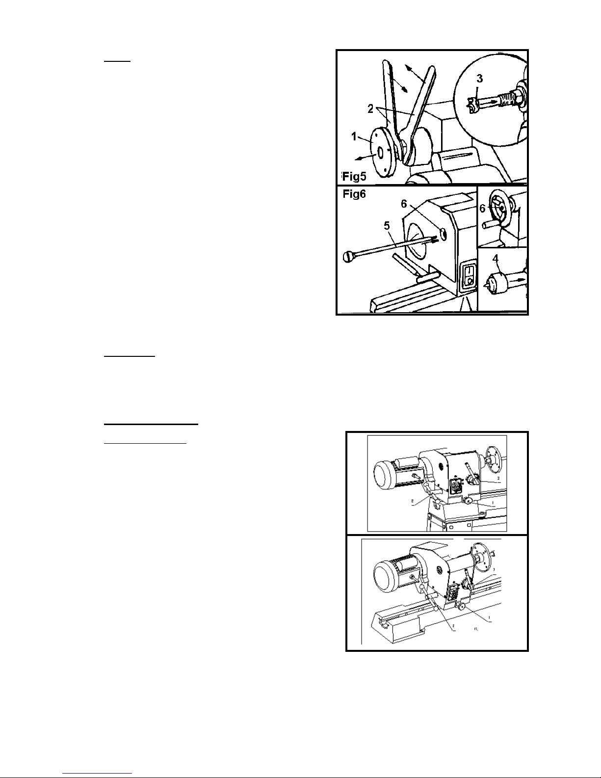
Spurs
1. Remove the faceplate [1] from the headstock spindle
using the two wrenches provided [2] to separate the
faceplate from the spindle nut. (Fig5)
2. Insert the headstock spur [3] in the spindle hole.
3. Insert the live center [4] in the tailstock hole. (Fig
6)
4. To remove either the headstock spur or the tailstock
center insert the push-out rod [5] into the hole [6] at
the opposite end of the headstock or tailstock. Remove
and store the rod in a safe location after use.
WARNING! Do not operate your wood lathe until it is completely assembled and adjusted
according to the instructions.
Adjustments
Headstock (Fig 7)
1. The headstock has 5 preset positions, 00 setting for all
spindle turning applications, 600/900/1200for use when
making face plate turnings, 1800for use for face plate
turnings when using the extension bed and tool rest.
2. To set the headstock at the desired position, you must
first turn the head lock handle [2] until you have
completed at least one rotation. (Fig 8)
3. Pull out the headstock release [1], rotate the entire
headstock clockwise to the desired position. The
headstock will be fixed in position when it clocks into one
of the five pre-set settings. Tighten the lock handle [2].
7
Operation
Switch (Fig 9)
The lathe is fitted with a no-volt switch. In the
event of a power supply failure the wood lathe
needs to be manually re-started by pushing the “I”
button on the switch.
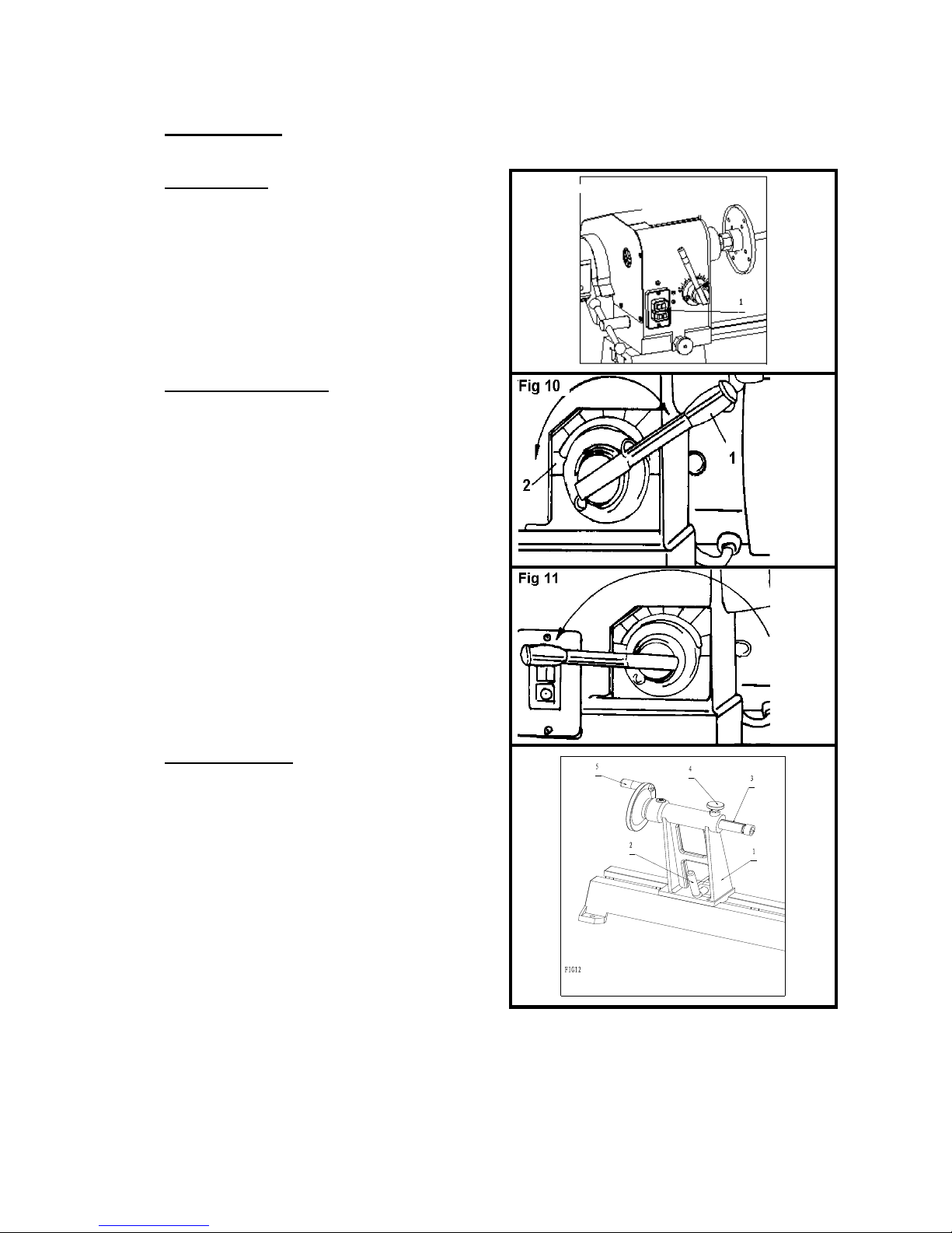
Speed control (Fig 10)
1. The lathe motor must be running before you can
use the speed control lever.
2. The speed control lever can be turned to one of
ten fixed speeds. To set the speed, pull back on the
lever handle [1] and rotate the handle to the next
fixed speed. Use the index plate [2] to choose right
lathe speed.
3. Turn the lever clockwise to increase the speed
and turn counterclockwise to decrease the speed.
4. You must move the speed control lever to the
lowest speed setting before turning the switch off
(Fig 11), otherwise the motor may not start or be
damaged.
Tailstock (Fig 12)
1. Move the tailstock [1] by loosening the lock lever
[2] and pushing the tailstock to the desired position
on the bed. Lock by tightening the lock lever [2].
2. The spindle can extend up to 57mm from the
tailstock housing. You can move the tailstock
spindle [3] by loosening the spindle lock lever [4]
and then turning the hand wheel [5]. Lock the
levers [4] and [2] before operating lathe.
3. The tailstock spindle is hollow and can be
accessed from the hand wheel end. Use the
push-out rod to remove the center cup or to drill
holes through the center of a workpiece.
8
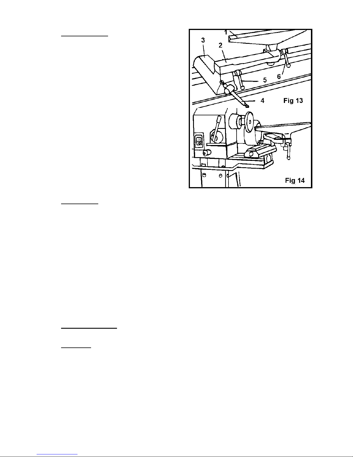
Tool rest (Fig 13)
1. The tool rest [1] can be used with or without the
arm [2].
2. To move the tool rest base [3], loosen the lock
lever [4], and move the base to the right or left and
back or front. Tighten the lever [4] when the tool
rest base is in the desired position.
3. When using the arm [2], make the necessary
adjustments using lick levers [5] and [6] to position
the tool rest.
4. Tighten all tool rest lever and handles [4-5-6]
and ensure there is adequate clearance between
the workpiece and the tool rest assembly before
turning the lathe on.
5. The tool rest can also be repositioned to the
extension bed for use on outboard turnings. (Fig
14)
IMPORTANT ! MAKE SURE THE TOOL REST IS ADJUSTED TO BE AS CLOSE TO THE
WORKPIECE AS POSSIBLE. ROTATE THE WORKPIECE BY HAND TO CHECK CLEARANCE BEFORE
TURNING THE LATHE ON.
Maintenance
WARNING! FOR YOUR OWN SAFETY, PUSH THE BUTTON "O" ON THE SWITCH AND REMOVE
THE PLUG FROM THE ELECTRICAL OUTLET BEFORE PERFORMING MAINTENANCE OR
LUBRICATION WORK ON THE LATHE.
1. Blow out dust accumulated inside the motor, housing, and bed assembly frequently.
2. A coat of automotive wax applied to the bed will help keep the surface clean and keep the
smooth movement of the tool rest and tailstock.
3. Periodic lubrication of the spring levers and other threaded parts will make these parts easier
to operate.

PARTS LIST
Part No
Description
Size
Q’ty
Part No
Description
Size
Q’ty
W1
Screw
M5X8
4
W50
“C” ring
24
1
W2
Cover –motor
1
W51
Lever
1
W3
Hex screw
M8X30
3
W52
Handle
1
W4
Washer
3
W53
Screw
M8x25
1
W5
Motor
1
W54
Nut
M8
2
W6
Pin-injection
1
W55
Screw
M5x12
2
W7
“C'' ring
24
1
W56
Plate
1
W8
Screw
M6
2
W57
Bed
1
W9
Motor Pulley Set, L&R
1
W58
Bolt
M8x35
8
W10
“C” ring
62
1
W59
“C” ring
19
1
W11
Bearing
6007
1
W60
Handle
1
W12
Bracket-Shifting Lever
1
W61
Shaft
1
W13
“C” ring
35
1
W62
Tool Rest Body
1
W14
Rack
1
W63
Nut
M18
1
W15
Switch Box
1
W64
Clamp
1
W16
Headstock
1
W65
Bolt-A
1
W17
Key 4x4x80
1
W66
Handle Assembly
1
W18
“C” ring
16
1
W67
“C” ring
19
1
W19
Sleeve
1
W68
Handle Assembly
1
W20
Spring
1
W69
Extension Tool Rest
1
W21
Spindle Pulley Set, L&R
1
W70
Tool Rest
1
W22
V-Belt 625
1
W71
Center
1
W23
“C” ring
16
1
W72
Shaft
1
W24
Plastic Jaw Nut M20x1.5
3
W73
Tailstock
1
W25
Power Wire
1
W74
Tail Spindle
1
W30
Wrench
2
W75
Quill Locking Screw
1
W31
Drive Center
1
W76
Cone Set Screw
1
W32
Disc
1
W77
Handle Wheel
1
W33
Spindle
1
W78
Handle
1
W34
Key 4x4x80
1
W79
“C” ring
10
1
W35
Bearing
6205
1
W80
Special Bolt
1
W36
“C” ring
52
1
W81
Clamp
1
W37
“C” ring
52
1
W82
Nut
M10
1
W38
Bearing
6205
1
W83
Screw
M5x12
2
W40
“C” ring
24
1
W84
Plate
1
W41
Label for Sped
1
W85
Washer
8
4
W42
Gear Assembly
1
W86
Nut
M8
4
W43
Screw
M5x12
2
W87
Leg
1
W44
Screw
M4x12
3
W88
Leg
1
W45
Angular setting assembly
1
W89
Switch
1
W46
Special Screw
1
W47
Index Bracket
1
W48
Clamp
1
W49
Nut
M18
1
10
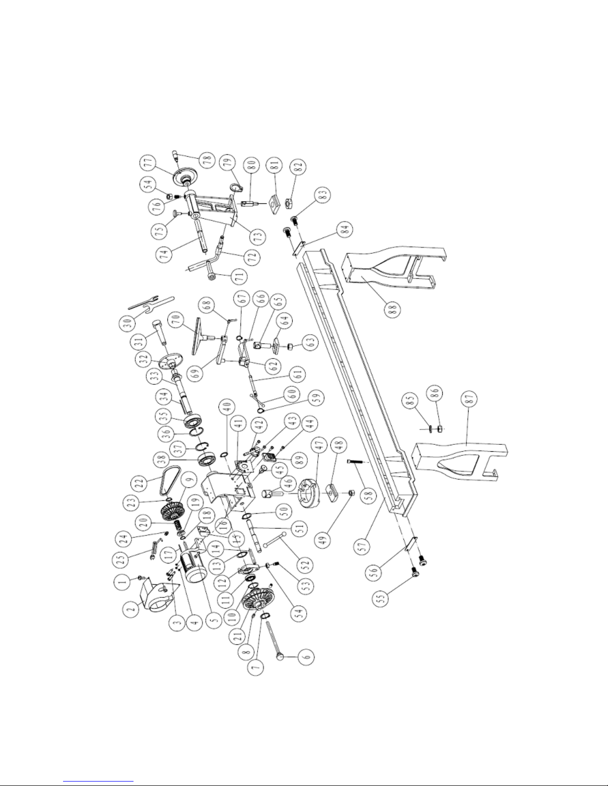
PARTS DIAGRAM:
11
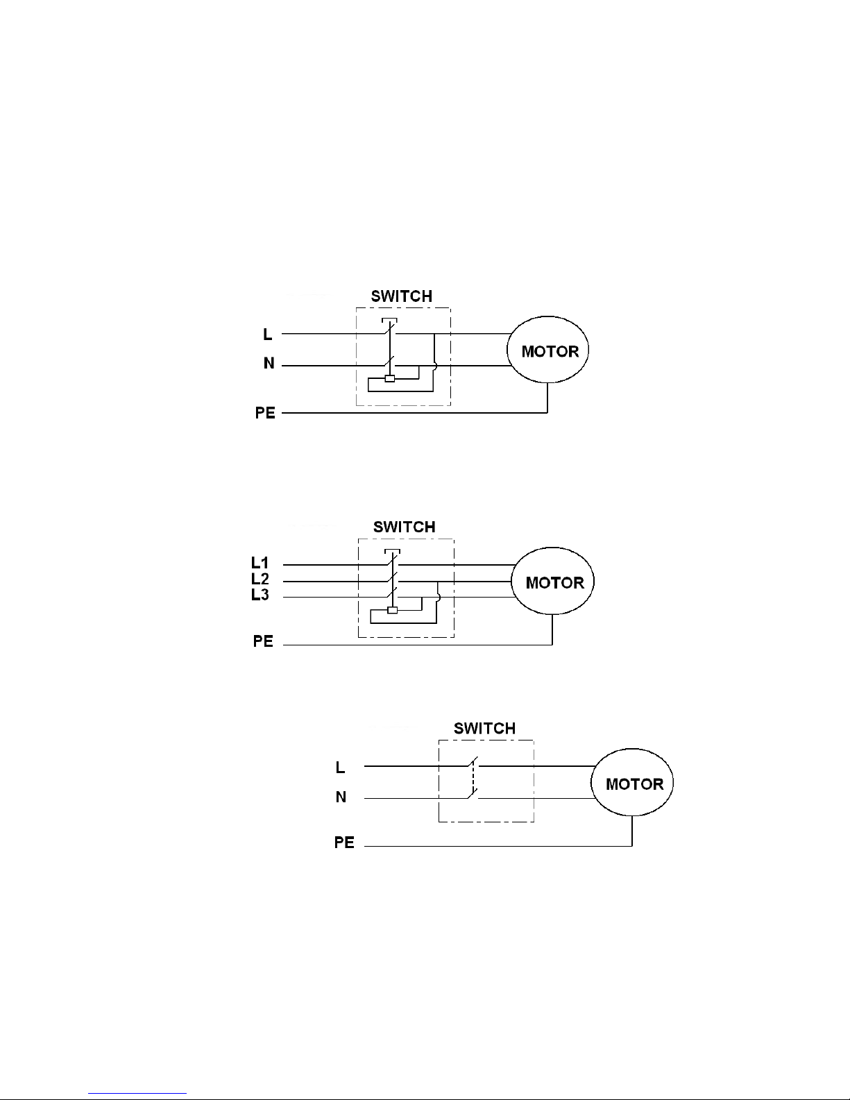
WIRING DIAGRAM:
1.220-240V/50Hz, 1 Phase
2.380-400V/50Hz, 3 Phase
3. 110-120V/60Hz, 1 Phase
Table of contents
Popular Lathe manuals by other brands

WoodFast
WoodFast WL1216B instruction manual

Climax
Climax BB4500 operating manual

Clarke
Clarke WOODWORKER CWL325V Operation & maintenance instructions

Gude
Gude GMH 2000 Translation of the original instructions

Scheppach
Scheppach 4902301901 Translation from the original instruction manual

tornos
tornos MultiDeco Series Equipment Logbook Assembly, operation and maintenance


