PSI Woodworking Products TurncrafterPro TCLPRO User manual
TurncrafterPro™Lathe
Model #TCLPRO
User’s Manual
9900 Global Rd.
Philadelphia ,PA. 19115
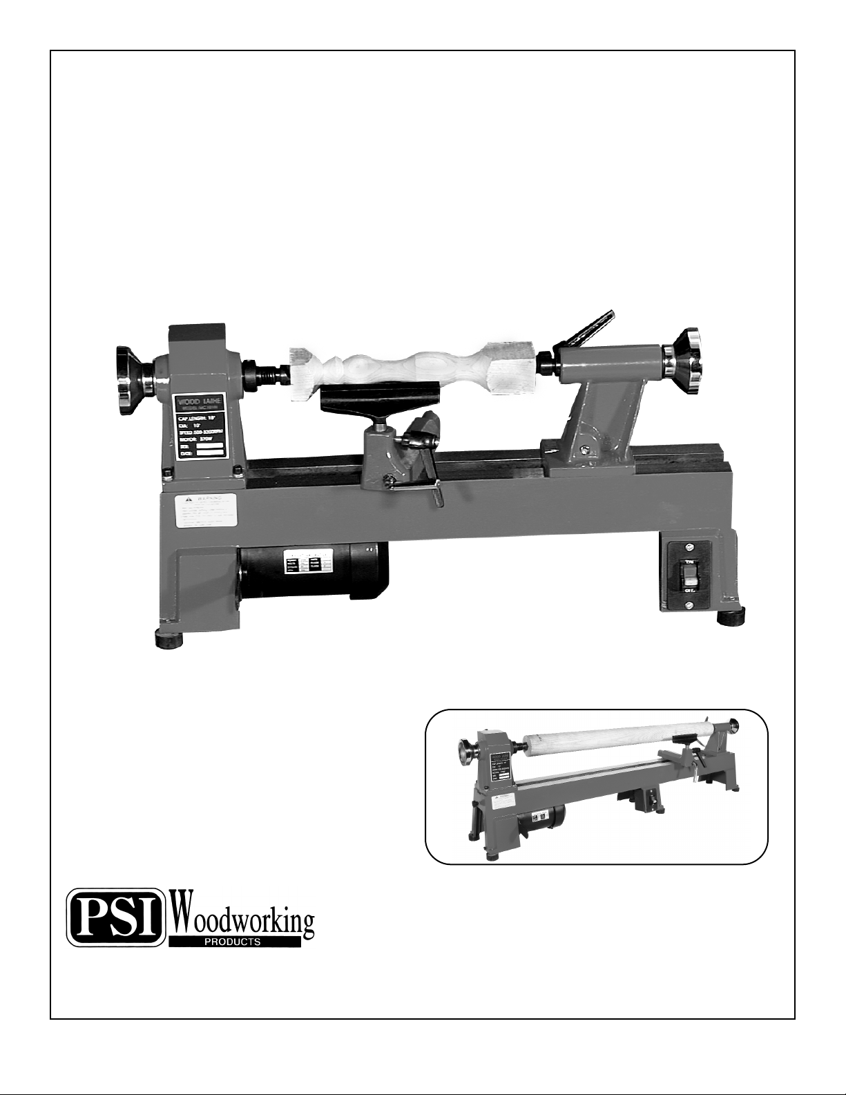
Turn up to 39" with the #TCLPROXB
extension bed.(not included)
Read this manual completely before usage.
Ve rsion 2 – 03/05

2
SPECIFICATIONS OF TURNCRAFTERPRO™ MIDI LATHE
Model number: . . . . . . . . . . . . . . . . . . . . . . . . . . . . . . . . . . . . . . . . . . . . . . . . . . . . . . . . . . .#TCLPRO
Motor: . . . . . . . . . . . . . . . . . . . . . . . . . . . . . . . . . . . . . . . . . . . . . . . . . . . . . . . . . 1/2 HP, 120V AC, 8A
Distance between centers: . . . . . . . . . . . . . . . . . . . . . . . . . . . . . . . . . . . . . . . . . . . . . . . . . . . . . . . 18"
Distance between centers with extension bed: . . . . . . . . . . . . . . . . . . . . . . . . . . . . . . . . . . . . . . 39"
Swing over bed: . . . . . . . . . . . . . . . . . . . . . . . . . . . . . . . . . . . . . . . . . . . . . . . . . . . . . . . . . . . . . . . . 10"
Head stock spindle thread: . . . . . . . . . . . . . . . . . . . . . . . . . . . . . . . . . . . . . . . . . . . . . . . . . . 1" x 8tpi
Hollow head stock . . . . . . . . . . . . . . . . . . . . . . . . . . . . . . . . . . . . . . . . . . . . . . . . . . . #2 morse taper
Hollow tail stock . . . . . . . . . . . . . . . . . . . . . . . . . . . . . . . . . . . . . . . . . . . . . . . . . . . . . #2 morse taper
5 (five) speed: . . . . . . . . . . . . . . . . . . . . . . . . . . . . . . . . . . . . . . . . . . . . . . . . . . . . . 500 to 3200 RPM
Overall Size: . . . . . . . . . . . . . . . . . . . . . . . . . . . . . . . . . . . . . . . . . . . . . . 30"L x 7-1/4" W x 14-1/2"H
Overall Size with extension bed: . . . . . . . . . . . . . . . . . . . . . . . . . . . . . 54"L x 7-1/4" W x 14-1/2"H
Net weight (lathe only): . . . . . . . . . . . . . . . . . . . . . . . . . . . . . . . . . . . . . . . . . . . . . . . . . . . . . . 68 lbs.
Net weight with extension bed: . . . . . . . . . . . . . . . . . . . . . . . . . . . . . . . . . . . . . . . . . . . . . . . . 87 lbs.
WARRANTY
THE TURNCRAFTERPRO™ LATHE IS WARRANTED AGAINST
DEFECTS IN MATERIALS AND WORKMANSHIP FOR A PERIOD
OF THREE (3) YEARS FROM THE DATE OF PURCHASE. THIS
WARRANTY APPLIES TO THE PURCHASER OF THIS PRODUCT,
AND IS LIMITED TO THE REPAIR OR REPLACEMENT OF THE
PRODUCT OR ITS PARTS AT PSI WOODWORKING PRODUCTS’
DISCRETION. EXCLUDED ARE PARTS WHICH HAVE BEEN
MISUSED, ABUSED, ALTERED OR CONSUMED BY NORMAL
OPERATION OF THE MACHINE. ALSO EXCLUDED ARE DIRECT
OR CONSEQUENTIAL DAMAGES TO PERSONS, PROPERTY,
AND/OR MATERIALS. YOUR INVOICE SERVES AS PROOF OF
PURCHASE AND MUST BE REFERENCED PRIOR TO RETURN
AUTHORIZATION.
__________________________ ______________
DATE PURCHASED INVOICE NO.

3
SAFETY INSTRUCTIONS
1. Read and understand instruction manual.
2. NEVER connect plug to power source until full assembly steps have been completed.
3. Check that your supply voltage and grounding are correct.
4. Do not use the lathe in a damp or wet location.
5. Keep lathe clean and lightly oiled.
6. Make sure the belt and pulley are adequately guarded at all times.
7. Always remove any tools, chuck keys, toggle bars, etc. when you are finished with them.
8. Keep the work area well lit and provide adequate ventilation and workspace.
9. Keep young children and bystanders at a safe distance from the lathe.
10. Do not force the lathe to do more than what it is designed to do.
11. Do not wear loose clothing, jewelry, or neckties which could get caught in revolving parts. It is recommended that long
hair be restrained.
12. Safety eye wear should be worn at all times. Also, it is recommended to a use of face or dust mask during lathe
operation.
13. Attach all workpieces securely to the lathe, whether between centers, on face plates, or in chucks, etc.
14. For best results be sure to keep tools sharp, clean, and free from rust.
15. Use only three wire extension cords that have 3-prong grounding type plugs and 3-hole receptacles that accept the
tool's plug.
16. Check the speed BEFORE mounting any material onto the lathe. ALWAYS start the lathe at a slow speed.
17. Keep the door to the pulleys and belts securely screwed closed during lathe operation.
4
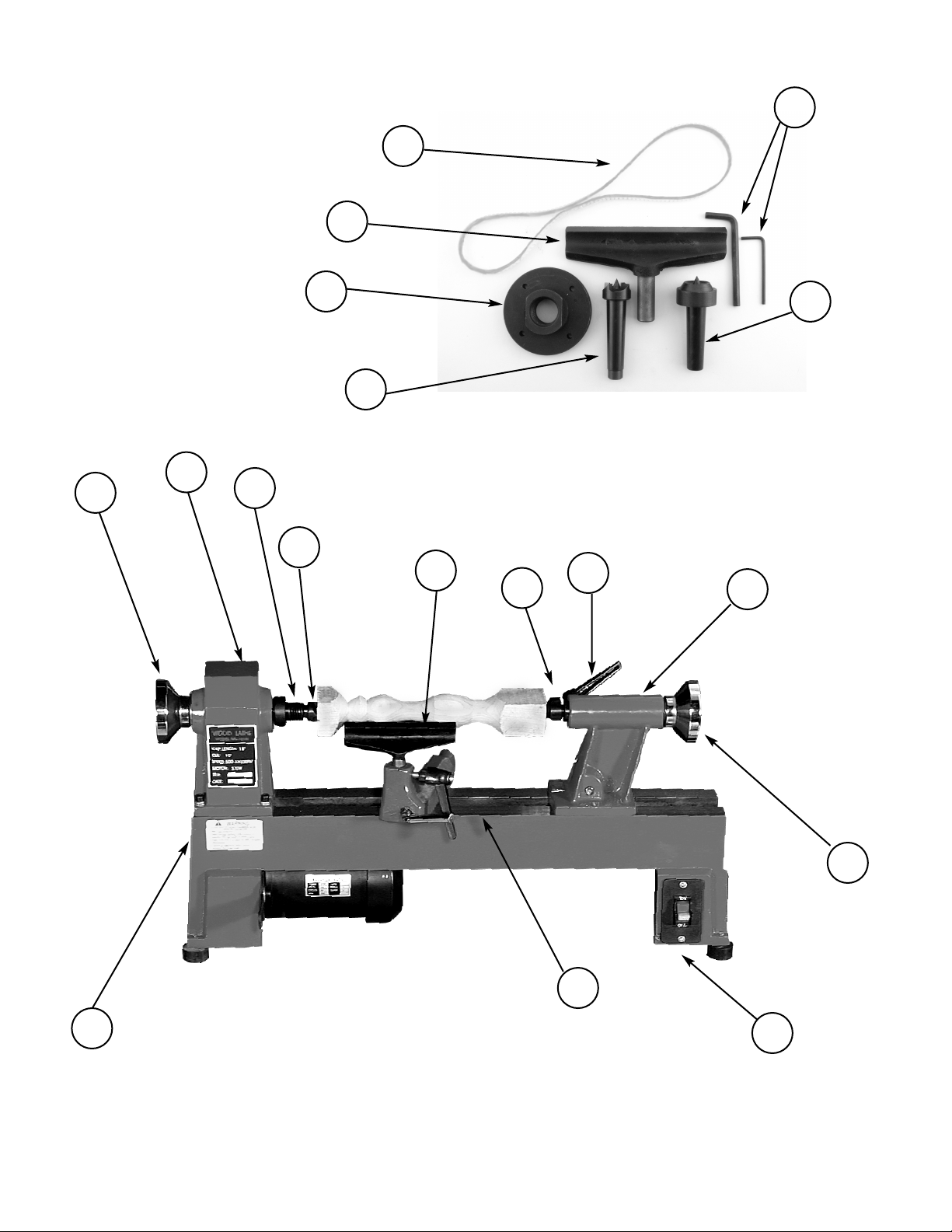
1. Hand wheel
2. Tail stock
3. Live center
4. Tool rest
5. Spur center
6. Headstock spindle
7. Rear belt door
8. Hand wheel
9. Side belt door
10. Bed
11. On/Off switch
12. Tailstock handle
PARTS
ASSEMBLY
8
Package Includes
1. 6" Toolrest
2. 3" Faceplate
3. #2 MT spur center
4. #2 MT live tail
5. Spare drive belt
6. 2 Hex wrenches
76
5
4312 2
1
11
10
9
5
3
6
1
24

5
Motor Pulley
To adjust t u r n in g sp eeds, open the access
doors to the motor pulley and headstock
pulley and align the belt as indicated in
figure on left.
Note that speeds vary from 500 RPM
to 3200 RPM.
Headstock
pulley
RECOMMENDED TURNING SPEEDS
Work Diameter in Inches . . . . . . . . . . . . . . . . . . . . . . . . . . . . . . . . . . . . . . . . . . . . . Speeds
0-2" . . . . . . . . . . . . . . . . . . . . . . . . . . . . . . . . . . . . . . . . . . . . . . . . . . . . . . . 2600-3200 RPM
2"-3" . . . . . . . . . . . . . . . . . . . . . . . . . . . . . . . . . . . . . . . . . . . . . . . . . . . . . . 2000-2600 RPM
3"-4" . . . . . . . . . . . . . . . . . . . . . . . . . . . . . . . . . . . . . . . . . . . . . . . . . . . . . . 1300-2000 RPM
4"-5". . . . . . . . . . . . . . . . . . . . . . . . . . . . . . . . . . . . . . . . . . . . . . . . . . . . . . . . 500-1300 RPM
6"+. . . . . . . . . . . . . . . . . . . . . . . . . . . . . . . . . . . . . . . . . . . . . . . . . . . . . . . . . . . . . . 500 RPM
Note: These speeds can vary with different wood species and the skill of the operator.
Unbalanced pieces generally should be turned on speeds lower than those recommended above.
Sanding
Use the fastest speed possible without burning the wood.
Polishing & Finishing
Generally finishing can be done at faster speeds than turning
ADJUSTING THE MAIN SPINDLES SPEED
(Number callouts refer to the Parts List on page 7)
First, open the rear belt door (#20) of headstock (#19). Loosen the ratchet handle (#33), to allow the motor plate (#31)
to swivel upwards. Open the side belt door (#55) to gain access to the motor pulley. Change the speed by moving the
drive belt (#26) from one pulley to another (always go from larger pulley to smaller pulley)making sure that the belt
runs in parallel grooves at all times.When finished changing, pull down the motor plate to tighten the belt, then secure
the ratchet handle (#33). Affix the rear belt door (#20) to the head stock (#19) and secure the side belt door (#55).
3200
2600
2000
1300
500
Speed Chart

6
BELT, SPINDLE AND BEARING REPLACEMENT FOR THE #TCLPRO LATHE
To change the belt (#26), spindle (#14), or bearings (#15 and 18) for the lathe, you must first loosen the two set screws (#28) and
hand wheel (#22). Next remove the access door (#20, #21, and #52) and loosen the set screw (#24) on the drive pulley (#25).
Tap out the spindle using a mallet. If you do not have a mallet, place a block of wood against the spindle and tap with a
hammer. To get the spindle completely out, use a flat head screwdriver to punch it the rest of the way. Be careful not to damage
the bearings or the threads.
Replace the bearings, spindle or belt as required.
BELT:Yo u n eed only to move the spindle enough to slide a new belt on.
SPINDLE: Yo u m u s t k no c k the spindle completely out through both bearings.
BEARINGS: After removal of the spindle, completely – knock out the bearings from the inside of the headstock. This is best
accomplished by inserting a long rod or screwdriver through one bearing inside the headstock toward the
opposite bearing. Tap firmly to remove the bearing from the casting. Do the same for the second bearing.
Please be aware not to damage the retainers (#16 and #17) when tapping out the bearings.
Reassemble the new bearings by tapping them into place from the outside. Replace the spindle.
Note: Yo u may have to loosen the ratchet handle (#33) to reinstall the spindle pulley and belt. Reinstall the hand wheel and set
screws. DO NOT tighten the hand wheel against the bearings. Tighten the pulley set screw and close the access door.

7
No. Part# Description Qty No. Part# Description Qty
1ZTCL3-01 BED 1 29 ZTCL3-29 MOTOR PULLEY 3
2ZTCL3-02 SEMI-CIRCLE HEAD SCREW 2 30 ZTCL3-30 FLAT HEAD SCREW 2
3ZTCL3-03 RETAINING PLATE 1 31 ZTCL3-31 MOTOR PLATE WITH NOTCH 1
4ZTCL3-04 HAND WHEEL 1 32 ZTCL3-32 MOTOR 1
5ZTCL3-05 TAILSTOCK 1 33 ZTCL3-33 RATCHET HANDLE
6ZTCL3-06 LOCK LEVER 1 34 ZTCL3-34 RING RETAINING 12 2
7ZTCL3-07 ECCENTRIC AXIS 1 35 ZTCL3-35 TOOL REST 1
8ZTCL3-08 TAIL AXIS 1 36 ZTCL3-36 TOOL REST BASE 1
9ZTCL3-09 TAPER ROD 1 37 ZTCL3-37 BOLT 1
10 ZTCL3-10 BALL BEARING 1 38 ZTCL3-38 PLATE 4
11 ZTCL3-11 CUP CENTER 1 39 ZTCL3-39 HEX NUT 1
12 ZTCL3-LS HEADSTOCK SPUR CENTER 1 40 ZTCL3-40 LOCK HANDLE FOR CHISEL BASE
13 ZTCL3-13 FACE PLATE 1 41 ZTCL3-41 LOCK LEVER 1
14 ZTCL3-14 HEADSTOCK SPINDLE 1 42 ZTCL3-42 BOLT 1
15 ZTCL3-15 BALL BEARING 2 43 ZTCL3-43 LOCK PLATE 1
16 ZTCL3-16 RETAINING RING 1 44 ZTCL3-44 HEX NUT 1
17 ZTCL3-17 RETAINING RING 1 45 ZTCL3-45 POWER CORD 1
18 ZTCL3-18 BALL BEARING (202) 1 46 ZTCL3-46 SWITCH 1
19 ZTCL3-19 HEADSTOCK 1 47 ZTCL3-47 WARNING LABEL 2
20 ZTCL3-20 REAR BELT DOOR 1 48 ZTCL3-48 WASHER 8 4
21 ZTCL3-21 SEMI-CIRCLE HEAD SCREW 4 49 ZTCL3-49 SPRING WASHER
22 ZTCL3-22 BALANCE WHEEL 1 50 ZTCL3-50 RUBBER WASHER 4
23 ZTCL3-23 MARKING PLATE 1 51 ZTCL3-51 BIG WASHER 8 2
24 ZTCL3-24 HEX SOCKET SET SCREW 1 52 ZTCL3-52 WASHER 5 4
25 ZTCL3-25 DRIVE PULLEY 1 53 ZTCL3-53 RING RETAINING 10 1
26 ZTCL3-26 DRIVE BELT 1 54 ZTCL3-54 SEMI-CIRCLE HEAD SCREW M5X10 2
27 ZTCL3-27 HEX SOCKET SCREW M8x25 1 55 ZTCL3-55 SIDE BELT DOOR
28 ZTCL3-28 HEX SOCKET SCREW M6 x 10 4
55
33
PARTS LIST

OPTIONAL ACCESSORIES FOR TurncrafterPro™
DUPLICATING SYSTEM
PSI duplicator attachment . . . . . . . . . . . . . . . . . . . . . . . .#CML-DUPJ
Optional 2-ended carbide cutter . . . . . . . . . . . . . . . . . . .#CML-DUPX
Steel duplicator templates for a variety of projects.
HEADSTOCK ACCESSORIES
(1" x 8tpi or #2 Morse Taper)
1 -3/8" mini expanding collet chuck . . . . . . . . . #CXC4 & #CXCMT2
4-Jaw self-centering chuck . . . . . . . . . . . . . . . . . . . . . . . . . . . . . #C4J
3-Jaw self-centering chuck . . . . . . . . . . . . . . . . . . . . . . . . . . . #C3J-4
3/8" Drill chuck- #2 MT mount . . . . . . . . . . . . . . . . . . . . . . . .#TM22
1/2" Drill chuck- #2 MT mount . . . . . . . . . . . . . . . . . . . . . . . #TM32
Mini screw chuck . . . . . . . . . . . . . . . . . . . . . . . . . . . . . . #PK-TOP-MJ
5/16" Mini cup chuck – #1 MT mount . . . . . . . . . . . . . . . . . . . #CSC
Chisel Mate . . . . . . . . . . . . . . . . . . . . . . . . . . . . . . . . . . . . . . . . #LCM5
4-Piece Drive Center . . . . . . . . . . . . . . . . . . . . . . . . . . . . . . . #LCENT4
OTHER ACCESSORIES
Dust collection hood . . . . . . . . . . . . . . . . . . . . . . . . . . . . . #DLHOODC
Pen making mandrel- 1" x 8tpi . . . . . . . . . . . . . . . . . . . . . .#PKM-BL
Pen making mandrel- #2 MT . . . . . . . . . . . . . . . . . . . . . . #PKM-FLC
Extension bed . . . . . . . . . . . . . . . . . . . . . . . . . . . . . . . . . . #TCLPROXB
“S” Toolrest . . . . . . . . . . . . . . . . . . . . . . . . . . . . . . . . . . . . . . . . #CLTSJ
“V” Toolrest . . . . . . . . . . . . . . . . . . . . . . . . . . . . . . . . . . . . . . . . #CVTJ
8" Toolrest . . . . . . . . . . . . . . . . . . . . . . . . . . . . . . . . . . . . . . . . #CLT8JE
12" Toolrest . . . . . . . . . . . . . . . . . . . . . . . . . . . . . . . . . . . . . #CLT12JE
9900 Global Road
Philadelphia, PA 19115
© 2004 PSI Woodworking Products
TurnCrafterPro™ Lathe #TCLPRO - V2
This manual suits for next models
1
Table of contents
Other PSI Woodworking Products Lathe manuals


Popular Lathe manuals by other brands

PSI Woodworking
PSI Woodworking Turncrafters Commander KWL1018VS user manual

Robust
Robust American Beauty owner's manual

Central Machinery
Central Machinery 03173 Assembly and operating instructions

Hardinge
Hardinge Talent 6/45 Maintenance manual

CabKing
CabKing 8V1 instruction manual

Gude
Gude GMD 400 Translation of original operating instructions


