Jefferson JEFSWMIT12-110 User manual

User Manual
v.1.2
JEFSWMIT12-110
JEFSWMIT12-230
SLIDING COMPOUND
MITRE SAW
2000W • GEAR DRIVEN MOTOR • LASER GUIDE • DOUBLE BEVEL
305mm


3
USER MANUAL V1.2
JEFSWMIT12-110 •JEFSWMIT12-230
305mm SLIDING COMPOUND MITRE SAW
1. Contents
1. Contents
2. Technical Specification & Cutting Capacity
3. Safety Information
4. Unpacking & assembly
5. Adjustments
6. Cutting Operations
7. Replacing / Installing a Blade
8. Maintenance
9. Parts Identification
2
3
4
7
8
11
13
14
16

4
USER MANUAL V1.2
JEFSWMIT12-110 •JEFSWMIT12-230
305mm SLIDING COMPOUND MITRE SAW
RATED SUPPLY VOLTAGE: 230V (13A) / 110V (16A)* - 50Hz
OUTPUT: 2000W (2.7HP)
MOTOR TYPE: GEAR DRIVEN
NO LOAD SPEED: 4500RPM
BLADE DIAMETER: 12" / 305MM
BLADE BORE: Ø 30MM
MITRE RANGE: -45˚ / 0˚ / +45
DUST EXTRACTION PORT: Ø 35MM
PRESET MITRE LOCKS: 0˚, 15˚, 22.5˚, 30˚, 45˚
NET WEIGHT: 22KG
*Rated Voltage as indicated on box & equipment specification plate
2. Technical Specication
2.1 Cutting Capacity:
Please refer to the adjacent table
for guidelines on the respective cutting
capacities for this equipment.
Visit our website to see our full range of
replacement Cutting Discs, TCT Blades,
and other abrasives.
www.jeffersontools.com

5
USER MANUAL V1.2
JEFSWMIT12-110 •JEFSWMIT12-230
305mm SLIDING COMPOUND MITRE SAW
1. KNOW YOUR TOOL
Read and understand the owners manual and labels affixed to the tool. Learn its application and limitations
as well as its specific potential hazards.
2. GROUND THE TOOL.
This tool is equipped with an approved 3-conductor cord and a 3-prong grounding type plug to fit the proper grounding type receptacle. The
green conductor in the cord is the grounding wire. NEVER connect the green wire to a live terminal.
3. KEEP GUARDS IN PLACE.
Keep in good working order, properly adjusted and aligned.
4. REMOVE ADJUSTING KEYS AND WRENCHES.
Form habit of checking to see that keys and adjusting wrenches are removed from tool before turning it on.
5. KEEP WORK AREA CLEAN.
Cluttered areas and benches invite accidents. Do not leave tools or pieces of wood on the machine while operating.
6. AVOID DANGEROUS ENVIRONMENT.
Don’t use power tools in damp or wet locations or expose them to rain. Keep work area well lit and provide adequate surrounding work
space.
7. KEEP CHILDREN AND VISITORS AWAY.
All visitors should be kept a safe distance from work area.
8. MAKE WORKSHOP CHILD-PROOF.
Use padlocks, master switches or remove starter keys.
9. USE PROPER SPEED.
A tool will do a better and safer job when operated at the proper speed.
10. USE RIGHT TOOL.
Don’t force the tool or the attachment to do a job for which it was not designed.
11. WEAR PROPER APPAREL.
Do not wear loose clothing, gloves, neckties or jewelry (rings, watch) because they could get caught in moving parts.Non-slip footwear is
recommended. Wear protective hair covering to contain long hair. Roll up long sleeves above the elbows.
12. ALWAYS WEAR SAFETY GLASSES.
Always wear safety glasses (ANSI Z87.1). Everyday eyeglasses only have impact resistant lenses, they are NOT safety glasses. Also use a
face or dust mask if cutting operation is dusty.
13. DON’T OVERREACH.
Keep proper footing and balance at all times.
14. MAINTAIN TOOL WITH CARE.
Keep tools sharp and clean for best and safest performance.Follow instructions for lubricating and changing accessories.
15. DISCONNECT TOOLS.
Before servicing, when changing accessories or attachments.
16. AVOID ACCIDENTAL STARTING.
Make sure the switch is in the ‘’OFF’’ position before plugging in.
17. USE RECOMMENDED ACCESSORIES.
Consult the manual for recommended accessories. Follow the instructions that accompany the accessories. The use of improper accessories
may cause hazards.
18. NEVER STAND ON TOOL.
Serious injury could occur if the tool tips over. Do not store materials such that it is necessary to stand on the tool to reach them.
19. CHECK DAMAGED PARTS.
Before further use of the tool, a guard or other parts that are damaged should be carefully checked to ensure that they will operate properly
and perform their intended function. Check for alignment of moving parts, breakage of parts, mounting, and any other conditions that may
affect its operation. A guard or other parts that are damaged should be properly repaired or replaced.
20. NEVER LEAVE MACHINE RUNNING UNATTENDED.
Turn power ‘’OFF’’. Don’t leave any tool running until it comes to a complete stop.
3. Safety Information
3.1 General Safety

6
USER MANUAL V1.2
JEFSWMIT12-110 •JEFSWMIT12-230
305mm SLIDING COMPOUND MITRE SAW
3.2 Additional Safety Instructions for Sliding Compound Mitre Saw Blades
.
1. Use only cross-cutting saw blades. When using carbide tipped blades, do not use blades with deep guillets as they can deflect and contact
guard.
2. Do not operate the miter saw until it is completely assembled and installed according to the instructions.
3. If you are notthoroughly familiar with the operation of compound miter saws, obtain advice from your supervisor, instructor or other
qualified person.
4. Do notperform any operation freehand. Secure or clamp workpiece firmly against fence.
5. Warning: keep hands out of path of saw blade. If the workpiece you are cutting would cause your hand to be within 4” of the saw blade,
the workpiece should be clamped in place before making cut.
6. Be sureblade is sharp, runs freely and is free of vibration.
7. Allow the motor to come up to full speed before starting cut.
8. Keep motor air slots clean and free of chips.
9. Always make sureall clamp handles are tight before cutting even if the table is positioned in one of the mitre stops.
10. Be sureblade and flanges are clean and that arbor bolt is tightened securely.
11. Only useblade flanges specified for your saw.
12. Neveruse blades larger or smaller in diameter than 10”.
13. Neverapply lubricants to the blade when it is running.
14. Alwayscheck the blade for cracks or damage before operating. Replace cracked or damaged blade
Immediately.
15. Never use blades recommended for operation at less than 6000 rpm.
16. Use the blade guard at all times.
17. Always keep the lower blade guard in place and operating properly.
18. Never reach around or behind saw blade.
19. Make sure blade is not contacting workpiece before switch is turned on.
20. Never lock the switch in the "on" position.
21. Important: after completing cut, release power switch and wait for coasting blade to stop before returning saw to raised position.
22. Turn off the tool and wait for saw blade to stop before moving workpiece or changing settings.
23. Do notremove jammed or cut-off pieces until blade has stopped.
24. Never cut ferrous metals or masonry.
25. Never re-cut small pieces.
26. Provide adequate support to the sides of the saw table for long workpieces.
27. Never use the miter saw in an area with flammable liquids or gases.
28. Never use solvents to clean plastic parts. Solvents could possibly dissolve or otherwise damage the material. Only a soft damp cloth
should be used to clean plastic parts.
29. Disconnectpower by unplugging tool before changing blade or servicing.
30. Disconnectsaw from power source before leaving it.
31. Make surethe work area is cleaned before leaving the machine.

7
USER MANUAL V1.2
JEFSWMIT12-110 •JEFSWMIT12-230
305mm SLIDING COMPOUND MITRE SAW
3.3 Electrical Safety Information
All electrical connections must be done by a qualified electrician. Failure to comply may result in serious injury!
• All adjustments or repairs must be done with the miter saw disconnected from the power source.
Power supply
• Warning: this equipment must be connected to the correct power supply as indicated on the packaging and machine spec plate (230V or
110V) , Failure to connect in this way can result in injury from shock or fire.
Grounding
• This machine must be grounded. If it should malfunction or breakdown,grounding provides a path of least resistance for electric current, to
reduce the risk of electric shock. This machine is equipped with a cord having an equipment-grounding conductor and grounding plug. The
plug must be plugged into an appropriate outlet that is properly installed and grounded in accordance with all local codes and ordinances.
Your machine must be properly grounded. Not all outlets are properly grounded. If you are not sure if your Outlet is properly grounded, have it
checked by a qualified electrician.
Warning: to maintain proper grounding, do not remove or alter the grounding prong in any manner.
If not properly grounded, this machine can cause electrical shock, particularly when used in damp locations. To avoid shock or fire, if the
power cord is worn or damaged in any way, have it replaced immediately.
Extension cords
The use of any extension cord will cause some loss of power. Use the following table to determine the minimum wire size (a.W.G-american
wire gauge) extension cord. Use only 3-wire extension cords which have 3-prong grounding type plugs and 3-hole receptacles which accept
the tool’s plug.
For circuits that are further away from the electrical circuit box, the wire size must be increased proportionately in order to deliver ample volt-
age to the motor. Refer to fig.2 For wire length and size

8
USER MANUAL V1.2
JEFSWMIT12-110 •JEFSWMIT12-230
305mm SLIDING COMPOUND MITRE SAW
3.4 Working Environment
• Keep the work area clean. Cluttered workbenches increase the risk of accidents and injuries.
• Do not expose the tool to water or any other liquid. Do not use power tools in damp or wet areas. Do not expose power tools to rain.
• Make sure the work area is well lit.
• Keep onlookers and children at a safe distance. Onlookers should wear safety glasses and be kept at a safe distance from the work area.
• Do not allow onlookers to touch the tool or extension cord.
• Put away tools that are not being used. When not in use, store the tool in a dry place out of the reach of children.
• Always unplug the power cord when the tool is not being used, and before carrying out service work or changing accessories, such as blades,
bits or discs.
• Do not stand on the power tool. If the tool tips over or if you come in contact with the disc this can lead to serious injuries.
• Do not use power tools in explosive environments, for example, in the vicinity of flammable liquids, gases or dust.
• Cutting produces sparks. Do not use the tool near flammable materials – risk of fire and/or serious personal injury.
• If using the tool outdoors, only use an earthed extension cord approved for outdoor use.
•This appliance is not intended for use by persons (including children) with reduced physical, sensory or mental capabilities, or lack of
experience and knowledge, unless they have been given supervision or instruction concerning use of the appliance by a person responsible for
their safety.
• Do not use saw blades which are damaged or deformed;
- replace the table insert when worn;
- use only saw blades recommended by the manufacturer which conform to EN 847-1;
- do not use saw blades manufactured from high speed steel;
• Wear suitable personal protective equipment when necessary, this could include:
- hearing protection to reduce the risk of induced hearing loss
- eye protection when using the tool
- respiratory protection to reduce the risk of inhalation of harmful dust
- gloves for handling saw blades (saw blades shall be carried in a holder wherever practicable) and rough material
•Connect the saw to a dust collecting device when sawing wood. In addition the operator shall be informed of factors that influence
exposure of dust and the precautions mentioned e.g. type of material to be machined and the importance of local extraction (capture or source)
and proper adjustment of hoods/baffles/chutes.
• Select the correct saw blade for the material to be cut;
• Do not use the saw to cut other materials than those recommended by the manufacturer.
• Lifting and transportation information: Information shall include where to lift and support the mitre saw and when necessary a warning not to
use guards for this purpose.
• Do not use the saw without the guards in position, in good working order and properly maintained.
• Ensure that the arm is securely fixed when bevelling.
• Keep the floor area around the machine level, well maintained and free of loose materials e.g. chips and cut-offs.
•Provide adequate general or localised lighting.
•The operator is adequately trained in the use, adjustment and operation of the machine.
•Use correctly sharpened saw blades. Observe the maximum speed marked on the saw blade.
•Ensure that any spacers and spindle rings used are suitable for the purpose as stated by the manufacturer.
•Only use the laser fitted with the Mitre Saw.
•Repairs shall only be carried out by the laser manufacturer or an authorised agent.
•Blade replacement procedure including the method for repositioning and a warning that this must be carried out correctly.
•Refrain from removing any cut-offs or other parts of the workpiece from the cutting area whilst the machine is running and the saw head is not
in the rest position.
•Ensure that the machine is always fixed to a bench, wherever possible.
•Replace table insert when worn.
•Remove the plug from the socket before carrying out any adjustment, servicing or maintenance.

9
USER MANUAL V1.2
JEFSWMIT12-110 •JEFSWMIT12-230
305mm SLIDING COMPOUND MITRE SAW
3.5 General Safety Warnings for your Laser
1. WARNING : Read all safety warnings and all instructions. Failure to follow the warnings and instructions may result in serious injury.
2. Save all warnings and instructions for future reference.
3. These lasers do not normally present an optical hazard although staring at the beam may cause flash blindness.
4. Do not stare directly at the laser beam. A hazard may exist if you deliberately stare into the beam, please observe all safety rules as
follows:
5. The laser shall be used and maintained in accordance with the manufacturer’s instructions.
6. Never aim the beam at any person or an object other than the work piece.
7. The laser beam shall not be deliberately aimed at another person and shall be prevented from being directed towards the eye of a person
for longer than 0.25 seconds area.
8. Always ensure the laser beam is aimed at a sturdy work piece without reflective surfaces, e.g. wood or rough-coated surfaces are
acceptable. Bright shiny reflective sheet steel or similar is not suitable for laser applications as the reflective surface may direct the laser
beam back at the operator.
9. Do not change the laser device with a different type. The manufacturer or an authorized agent must carry out repairs.
10. CAUTION: Use of controls or adjustments other than those specified herein may result in hazardous radiation exposure.
The laser device fitted to this tool is CLASS 2 with a maximum radiation of <1mW and 650nm wavelength. Do not stare into the
beam
4. Unpacking & Assembly
Due to modern mass production techniques, it is unlikely that your Power tool is faulty or that
a part is missing. If you find anything wrong, donot operate the tool until the parts have been
replaced or the fault has been rectified. Failure to do so could result in serious personal injury.
1. Remove all loose parts from the carton.
2. Remove the packing materials from around the saw.
3. Carefully lift the saw from the carton and place it on a level work surface.
4. The saw has been shipped with the saw head locked in the down position.
To release the saw head, push down on the top of the saw arm, pull then turn the the saw head
release knob (A) Fig.1
WARNING: Do not lift the saw while holding on to the guards. Ue the top mounted carrying
handle.
Mitre Angle Lock Handle
The saw is supplied almost fully assembled, you should assemble the mitre lock handle (A) Fig.2
first. Attach the mitre handle by screwing it into position as shown. This handle is used to lock or
unlock the table at the desired mitre angle. Once the mitre angle is set, use the mitre lock handle
to lock the table.
Fig.1
Fig.2

10
USER MANUAL V1.2
JEFSWMIT12-110 •JEFSWMIT12-230
305mm SLIDING COMPOUND MITRE SAW
WARNING! Before making any cut, make sure the mitre lock handle is fully tightened.
Preset Mitre Locks
There are preset mitre stops at 0˚, 15˚, 22.5˚, 30˚ and 45˚ to the left and right.
While the table is being rotated, the table will stop at the next positive stop. Once the desired
angle is obtained, use the mitre lock handle to lock the table.
5. Adjustments
Bench Mounting
The saw base has holes to facilitate bench mounting.
1. Fix the saw to a bench using 4 hex. bolts and hex. nuts.
2. If desired, you can mount the saw to a piece of 13mm or thicker plywood which can then be clamped to your work support or moved to
other job sites and reclamped.
CAUTION: Make sure that the mounting surface is not warped as an uneven surface can cause binding and inaccurate sawing.
Vise Assembly (Vertical)
The vertical vise (A) Fig.3 can be installed in two positions on either the left or right side
of the guide fence. Insert the vise rod (B) into the hole in the guide fence and tighten the
vise lock knob (C) to secure the vise rod.
Retractable Extension Wings
Before using this mitre saw, it is recommended to use the extension wings to support your
workpiece. Simply loosen extension wing lock knob (A) Fig.5, pull out the extension wing
(B) Fig.5 and secure it in place by tightening the extension wing lock knob (A). Repeat for
the other extension wing.
Dust Bag
The dust bag (A) Fig.5 fits into the dust bag adaptor (B) at the rear of the saw head. For more
efficient operation, empty the dust bag when it is no more than half full. This allows better air
flow through the bag.
Adjusting Fence Extensions
This mitre saw comes with a back fence with fence extensions (A) Fig.6 at both ends which
slide outwards for additional back support for those long workpieces. Please note that during
steep bevel cut operations, these fence extensions must be fully extended to not interfere with
the motor housing or blade guard. To adjust the position of each fence extension;
1. Loosen the fence extension cap screw (B) using supplied hex. key.
2. Loosen the fence extension rear lock knob (C).
3. Slide the fence extension outwards to the desired position and retighten the cap screw and
rear lock knob. Fig.6
Fig.5
Fig.4
Fig.3

11
USER MANUAL V1.2
JEFSWMIT12-110 •JEFSWMIT12-230
305mm SLIDING COMPOUND MITRE SAW
Adjusting Bevel Angle
This mitre saw is capable of dual bevel angles which means the saw head can be inclined
or tilted towards the right or the left. To adjust the saw head to any bevel angle;
Loosen the bevel lock knob (A) Fig.9 and pull the positive stop adjustment knob (B)
outwards as shown. At this point, the saw head can be inclined to any angle you desire. If you
require a predetermined bevel angle of 0˚, push the adjustment knob inwards and pivot the
saw head until it stops at 0˚. Once the desired bevel angle is obtained, it is very important that
you retighten the bevel lock knob (A).
Depth Of Cut Stop Adjustment
In its normal position, the depth of cut stop Fig.7 permits the saw blade to cut right through a
workpiece. When the saw arm is lifted, the depth of cut stop (A) Fig.7 can be slid over towards
the front of the saw so that the depth adjustment screw (B) contacts the stop as the saw head
is lowered. This resricts the cut to a “adjusted depth” in the workpiece. The depth of cut can
be adjusted with the adjustment screw and locked in position with the lock nut (C) Fig8.
Setting The Blade Square With The Table
1. Make sure that the electrical plug is removed from the main power supply.
2. Push the saw head down to its lowest position, then pull and turn the head release knob to
hold the saw head in the transport position.
3. Loosen the mitre lock handle.
4. Rotate the table until the pointer is positioned at 0˚.
5. Retighten the mitre lock handle.
6. Loosen the bevel lock knob at the rear of the machine and set the saw arm at 0˚ bevel (the
blade at 90˚ to the mitre table). Tighten the bevel lock knob.
7. Place a square (A) Fig.10 against the table and the flat part of the blade body.
Fig.7
Fig.8
Fig.9
NOTE: Make sure that the square contacts the flat part of the saw blade body, not the teeth.
8.Rotate the blade by hand and check the blade-to-table alignment at several points.
9. The edge of the square and the saw blade should be parrallel.
10. If the saw blade angles away from the square, adjust as follows;
11. Make sure the positive stop adjustment knob (A) Fig.11 is pushed in all the way and the
bevel lock knob (B) is fully tightened. Loosen the two hex. screws (C & D) inside the pivot
bracket using a hex. key.
12. Loosen bevel lock knob (B) and adjust the head of the saw in or out to bring the saw blade
into alignment with the square.
13. Once perfectly aligned, retighten the bevel lock knob (B) and the two hex. screws (C & D)
inside the pivot bracket. Recheck the alignment.
14. Readjust bevel pointer (B) Fig.11 to line up with the 0º on the bevel scale.
Adjusting The 45˚ Stop Bolts
After setting the blade square with the table, the left and right side 45˚ stop bolts will need to
be adjusted.
1. Loosen the hex. nut and cap screw (F) Fig.11.
2. Tilt the head completely to the left side.
3. Place a 45˚ combination square against the table and the flat part of the blade body.
4.Once the head is at a perfect 45˚ angle,tighten bevel lock knob(B),then tighten the cap
screw(F)against the bevel lock knob(B)shaft and tighten hex. nut(F).
5. Repeat the above steps for the right side 45˚ stop bolt using the hex. nut and cap screw (E).
Fig.10
Fig.11

12
USER MANUAL V1.2
JEFSWMIT12-110 •JEFSWMIT12-230
305mm SLIDING COMPOUND MITRE SAW
Setting The Fence Square With The Blade
1. Make sure that the electrical plug is removed from the main power supply.
2. Push the saw head down to its lowest position, then pull and turn the head release knob to
hold the saw head in the transport position.
3. Loosen the mitre lock handle.
4. Rotate the table until the pointer is positioned at 0˚.
5. Retighten the mitre lock handle.
6.Loosen the bevel lock knob at the rear of the machine and set the saw arm at 0˚ bevel (the
blade at 90˚ to the mitre table).Tighten the bevel lock knob.
7.Place a square (A) Fig.13 against the fence (B) and the flat part of the blade.
NOTE: Make sure that the square contacts the flat part of the saw blade, not the teeth.
8. The edge of the square and the fence should be parrallel.
9. If the fence angles away from the square, adjust as follows;
10. Remove the fence extension cap screws, loosen the rear fence extension lock knobs and
remove fence extensions by sliding them off the fence. Loosen the now exposed fence cap
screws (C) Fig.13 on both sides and position the fence (B) against the square
and retighten all cap screws.
11. Reinstall fence extensions.
Fig.13
Using The Twin Laser Guide System
The twin laser guide system is controlled by the laser guide push button switch (A)
Fig.14 and will only turn on when the mitre saw is plugged into a power source.
Warning! Do not stare directly into the laser beams.
1. Mark the line of the cut on the workpiece.
2. Adjust the mitre and/or bevel angles as required.
3. Before clamping the workpiece in position using the vertical vise, align the line of cut on the workpiece
with the laser guide beam on either side of the blade kerf.
4. Start the motor.
5. When the blade reaches its maximum speed (approx. 2 sec.), lower the blade through the workpiece
Fig.14
Adjusting Twin Laser Guide System
If your laser guide does not seem to be aligned with both sides of the blade kerf, small adjust-
ments can be made.
1. Place a scrap piece of wood on the table and clamp it. Turn on mitre saw and make a partial
cut to indicate both sides of the blade kerf.
2. Turn laser guide On, then remove the laser guide protective plastic cover.
3. To move the entire laser guide assembly towards the right or left, loosen pan head screw (A)
Fig.15, move laser guide assembly to desired position and retighten pan head screw (A).
4. To adjust only one laser, loosen or tighten either the bottom pan head screw (B) to adjust the
bottom laser or the top pan head screw (C) to adjust the top laser. Adjust until the laser beams
are perfectly aligned with both sides of the blade kerf.
5. Reinstall the laser guide protective plastic cover.
Fig.15

13
USER MANUAL V1.2
JEFSWMIT12-110 •JEFSWMIT12-230
305mm SLIDING COMPOUND MITRE SAW
6. Cutting Operations
Crosscutting
When cutting a piece of wood it is not always necessary to use the slide mechanism. In these cases
make sure that the slide lock knob (A) Fig.16 is locked to prevent the saw arm from sliding.
A crosscut is made by cutting across the grain of the workpiece. A 90˚ crosscut is made with the mitre
and the bevel angles are set at 0˚.
1. Pull and turn the saw head release knob (A) Fig.17 and lift the saw head to its full height.
2. Loosen the mitre lock handle.
3. Rotate the mitre table using mitre handle until the pointer aligns with the 0º.
4. Retighten the mitre lock handle.
WARNING: Be sure to tighten the mitre lock handle before making a cut.
Failure to do so could result in the table moving during the cut and cause serious personal injury.
5. Place the workpiece flat on the table with one edge securely against the fence. If the board is warped,
place the convex side against the fence. If the concave side is place against the fence, the board could
break and jam the blade.
6. When cutting long pieces of timber, support the opposite end of the timber with the extension wing or
an additional roller stand or a work surface that is level with the saw table.
7. Use a vise or clamp to secure the workpiece whenever possible.
8. Before turning on the saw, perform a dry run of the cutting operation to check that there are no prob-
lems.
9. Hold the handle firmly and squeeze the trigger. Allow the blade to reach maximum speed.
10. Slowly lower the blade into and through the workpiece.
11. Release the switch trigger and allow the saw blade to stop rotating
before raising the blade out of the workpiece. Wait until the blade stops before removing the workpiece.
Cutting Wide Workpieces
When cutting wide workpieces, you should use the sliding action, unlock the slide lock knob (A)
Fig.16
1. Raise the saw head to its highest position and slide the blade towards you.
2. Hold the handle firmly and squeeze the trigger. Allow the blade to reach maximum speed.
3. Slowly lower the blade into the workpiece and slide it away from you at the same time until the work-
piece is cut.
4. Release the switch trigger and allow the saw blade to stop rotating before raising the blade out of the
workpiece. Wait until the blade stops before removing the workpiece.
Bevel Cut
A bevel cut is made by cutting across the grain of the workpiece with the blade angled to the fence and
mitre table. The mitre table is set at the 0º position and the saw head is set at an angle between 0˚ and 45˚
to the right or to the left.
1. Pull and turn the saw head release knob (A) Fig.17 and lift the saw head to its full height.
2. Loosen the mitre lock handle.
3. Rotate the mitre table until the pointer aligns with zero on mitre scale.
4. Retighten the mitre lock handle.
WARNING: Be sure to tighten the mitre lock handle before making a cut. Failure to do so could result in the
table moving during the cut and serious personal injury.
Fig.16

14
USER MANUAL V1.2
JEFSWMIT12-110 •JEFSWMIT12-230
305mm SLIDING COMPOUND MITRE SAW
5. Loosen the bevel lock knob (B) Fig.18 and move the saw arm to the desired bevel angle (between 0˚ and
45˚ to the right or left). Retighten the bevel lock knob.
6. Place the workpiece flat on the table with one edge securely against the fence. If the board is warped,
place the convex side against the fence. If the concave side is place against the fence, the board could break
and jam the blade.
7. When cutting long pieces of timber, support the opposite end of the timber with the extension wings.
8. Use the vise to secure the workpiece whenever possible.
9. Before turning on the saw, perform a dry run of the cutting operation to check that there are no problems.
10. Hold the handle firmly and squeeze the trigger. Allow the blade to reach maximum speed.
11. Slowly lower the blade into and through the workpiece.
12. Release the switch trigger and allow the saw blade to stop rotating before raising the blade out of the
workpiece. Wait until the blade stops before removing the workpiece.
Compound Cut
A compound cut involves using a mitre angle and a bevel angle at the same time. It is used in making picture
frames, to cut mouldings, making boxes with sloping sides and for roof framing. Always make a test cut on
a piece of scrap wood before cutting into good material. Use the slide action when cutting wide workpieces,
unlock slide by lossening lock knob (A) Fig.19
1. Pull and turn the saw head release knob (A) Fig.20 and lift the saw head to its full height.
2. Loosen the mitre lock handle.
3. Rotate the mitre table until the pointer aligns with the desired angle on the mitre scale.
4. Tighten the mitre lock handle.
Warning: Be sure to tighten the mitre lock knob before making a cut. Failure to do so could result in the table
moving during the cut and serious personal injury.
5. Loosen the bevel lock knob (B) Fig.21 and move the saw arm to the desired bevel angle (between 0˚ and
45˚ to the right or left). Tighten the bevel lock knob.
6. Place the workpiece flat on the table with one edge securely against the fence. If the board is warped,
place the convex side against the fence.
CAUTION: If the concave side is placed against the fence, the board should break and jam the blade.
7. When cutting long pieces of wood, support the long pieces using the extension wings.
8. Use the vertical vise to secure the workpiece whenever possible.
9. Before turning on the saw, perform a dry run of the cutting operation to check that there are no problems.
10. Hold the handle firmly and squeeze the trigger. Allow the blade to reach maximum speed.
11. Slowly lower the blade into and through the workpiece.
12. Release the trigger and allow the saw blade to stop rotating before raising the blade out of the workpiece.
Wait until the blade stops before moving the workpiece.
Fig.18
Fig.19
Fig.20
Fig.21
Bevel Cut
A bevel cut is made by cutting across the grain of the workpiece with the blade angled to the fence and
mitre table. The mitre table is set at the 0º position and the saw head is set at an angle between 0˚ and 45˚
to the right or to the left.
1. Pull and turn the saw head release knob (A) Fig.17 and lift the saw head to its full height.
2. Loosen the mitre lock handle.
3. Rotate the mitre table until the pointer aligns with zero on mitre scale.
4. Retighten the mitre lock handle.
WARNING: Be sure to tighten the mitre lock handle before making a cut. Failure to do so could result in the
table moving during the cut and serious personal injury.
Fig.17

15
USER MANUAL V1.2
JEFSWMIT12-110 •JEFSWMIT12-230
305mm SLIDING COMPOUND MITRE SAW
Fig.18
Fig.19
Fig.20
Fig.21
Fig.17
• WARNING: Never attempt to use a blade larger than the stated capacity of the saw (10”). It will come
into contact with the blade guards and housing.
• Never use a blade that is too thick to allow the outer blade flflange to engage with the flats on the
spindle. It will prevent the blade bolt from properly securing the blade on the spindle.
• Do not use this saw to cut metal or masonry.
1. Make sure that the power cord is removed from the main power supply.
2. Push down on the saw arm and pull and turn the saw head release knob to disengage the saw head.
3. Raise the saw head to its highest position.
4. Unscrew and remove large screw (A) Fig.22, and move the blade guard pivot link arm (B) out of the
way. Unscrew and remove pan head screw (C) which fixes the guard plate and lower blade guard to the
upper blade guard.
5. Once pan head screw (C) is removed, swing the guard plate and lower blade guard upwards to allow
access to the blade bolt as shown in Fig.23.
6. Completely depress the spindle lock button (A) Fig. 24 using one hand. Rotate the blade by hand until
the spindle locks.
7. Use the blade wrench (A) Fig.25 supplied to remove the blade bolt (B), loosen in a clockwise direction
as the blade bolt has a left hand thread.
8. Remove the outer blade flange (C) and the blade.
9. Wipe a drop of oil onto the inner and outer blade flanges.
10. Fit the new blade onto the spindle, make sure that the blade has the appropriate arbor size (5/8”)
and that the inner blade flange sits properly behind the blade.
CAUTION: Always install the blade with the blade teeth pointing downwards towards the fence. The
direction of the blade rotation is also stamped with an arrow on the upper blade guard.
11. Reposition the outer blade flange.
12. Depress the spindle lock, reposition and secure the blade bolt using the blade wrench. Tighten the
blade bolt in a counterclockwise direction as the blade bolt has a left hand thread.
13. Reposition the lower blade guard and guard plate and secure the guard plate with pan head screw
and large screw removed in step 4.
Fig.22
Fig.23
Fig.24
Fig.25
7. Replacing / installing a Blade

16
USER MANUAL V1.2
JEFSWMIT12-110 •JEFSWMIT12-230
305mm SLIDING COMPOUND MITRE SAW
Note: All the ball bearings are sealed and lubricated for life and will require no maintenance.
Cleaning
• After each use, wipe off chips and dust adhering to the tool with a cloth.
• Keep the blade guards and covers clean .
• Lubricate the sliding portions with machine oil to prevent rust.
To maintain product safety and reliability, repairs, any other maintenance or adjustment should be performed by your nearest authorized
service center.
8. Maintenance
Replacing Carbon Brushes
Remove and check the carbon brushes regularly (normally after 50 hours of use). The carbon brushes are
installed inside the motor housing. Using a screwdriver, remove the 2 pan head screws (B) Fig.26 that hold the
motor housing cap (A) in place.
Once the motor housing cap is removed, to release the carbon brush (B) Fig.27 from the holder, lower the
retaining spring (A). Disconnect the carbon brush wire (C) from the terminal, remove the carbon brush from the
motor housing and inspect it. Repeat this step for the second carbon brush.
Carbon brushes need to be replaced once they wear down to the limit mark, see Fig.28. Keep the carbon
brushes clean and free to slip in the holders. If they have worn down to the limit mark, purchase a set of identi-
cal replacement carbon brushes (both carbon brushes should be replaced at the same
time). Insert new carbon brushes into the holders, connect them to the terminals, reposition the retaining spring
and reinstall the motor housing cap using the 2 pan head screws.
Fig.26
Fig.27
Fig.28
17
USER MANUAL V1.2
JEFSWMIT12-110 •JEFSWMIT12-230
305mm SLIDING COMPOUND MITRE SAW
Fig.26
Fig.27
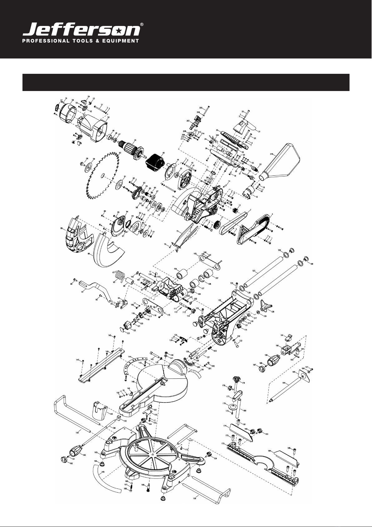
9. Parts Identication

18
USER MANUAL V1.2
JEFSWMIT12-110 •JEFSWMIT12-230
305mm SLIDING COMPOUND MITRE SAW
No Name Quantity No Name Quantity No Name Quantity
1Screw 4 51 Rubber boot 4 101 Pivot shaft 1
2Spring washer 29 52 Motor housing 2 102 Steel wire baffle ring 2
3Washer 13 53 Screw 2 103 Bracket 1
4Belt cover 1 54 Brush hold 2 104 Linear bearing 2
5Socket head screw 1 55 Brush spring 4 105 Bearing cover 1
6Washer 1 56 Brush 1 106 Screw 2
7Belt 1 57 Screw 1 107 Linear bearing 2
8Gear lock pin 1 58 Motor cover 1 108 Spring loop 1
9Gear lock pin spring 1 59 Logo cap 1 109 Knob(long) 1
10 E clip 1 60 Blade bolt 1 110 Socket head screw 1
11 Belt pulley(big) 1 61 Blade flange outer 1 111 Lock pin 1
12 Belt pulley(small) 1 62 Blade 4 112 Rolled pin 1
13 Screw 6 63 Gear case cover 1 113 Lock pin spring 1
14 Hex grub screw 1 64 Bearing 1 114 Lock pin cap 2
15 Exhaust port 1 65 Shaft gear 1 115 Bearing cover 1
16 Washer 5 66 Flat key 1 116 Laser fixed plate 1
17 Spring washer 10 67 Bearing 1 117 Screw 2
18 Screw 2 68 Key 1 118 Dual laser carrier 1
19 Screw 7 69 Spindle 1 119 Screw 1
20 Laser switch 1 70 C clip 1 120 Laser 2
21 Laser switch cap 1 71 Bearing 1 121 Screw 2
22 Cable plug 1 72 Gear 1 122 Laser case 1
23 Cord protector 1 73 Bearing 1 123 Laser window 1
24 Cold clamp 1 74 Fixed guard 1 124 Hex grub screw 4
25 Screw 5 75 Dust pipe run 1 125 Arm 1
26 Cold clamp 1 76 Sunk screw 3 126 Rubber ring 4
27 Screw 1 77 Nut 1 127 Slide 2
28 Transformer 1 78 Plate guarding(big) 1 128 Bevel lock handle 1
29 Trigger 1 79 Plate guarding(small) 1 129 Washer 1
30 Screw 2 80 Moving guard plate 1 130 Locknut 1
31 Carry handle 1 81 Big washer 1 131 Washer 1
32 Screw 1 82 Screw 1 132 Nut 3
33 Upper handle 1 83 Spring 1 133 Socket head screw 2
34 Binding post 1 84 Cast centre 1 134 Bevel pointer 1
35 Switch 1 85 Screw 1 135 Screw 2
36 Lower handle 1 86 Rivet 4 136 Bevel scale 1
37 Depth of cut adjust knob 1 87 Screw 1 137 Straight cut setting pin 1
38 Socket head screw 1 88 Moving guard 1 138 Stud 1
39 Nut 1 89 Moving guard cover 1 139 Stud 1
40 Knurled thin nut 1 90 Shoulder Screw 1 140 Locknut 1
41 Motor support 1 91 Linkage(A) 1 141 Washer 1
42 Screw 2 92 Rivet 1 142 Socket head screw 1
43 Bearing 1 93 Socket head screw 2 143 Screw 2
44 Fan baffle 1 94 Linkage(B) 1 144 Orientation board 1
45 Stator 1 95 Torsion spring 1 145 Screw 4
46 Armature 1 96 Spring bushing 1 146 Cutting insert 1
47 Bearing 1 97 Trench depth bracket 1 147 Screw 2
48 Wave washer 1 98 Spring piece 1 148 Turntable 1
49 Rubber boot 1 99 Wave wsher 1 149 Miter pointer 1
50 Motor housing 1 100 Screw 2 150 Screw 1

19
USER MANUAL V1.2
JEFSWMIT12-110 •JEFSWMIT12-230
305mm SLIDING COMPOUND MITRE SAW
No Name Quantity No Name Quantity
151 Turntable bolt 1 187 Lock handle cap 1
152 Turntable bolt cover 1 188 Screw 1
153 Screw 2 189 Lock handle 1
154 Knob(long) 2 190 Fixture 1
155 Safety foot 1 191 Locked nut 1
156 Lock boot 1 192 Pin 1
157 193 Roled pin 1
158 Lock bolt 1 194 Lock bolt 1
159 Support bar 2 195 Pressure plate 1
160 Lock handle 1 196 Washer 1
161 Screw 1 197 Screw 1
162 Lock handle cap 1 198 Lock washer 2
163 Base 1 199 Head sunk screw 2
164 Rubber foot 4 200 Orientation board(small) 1
165 Mitre scale 1 201 Spring washer 2
166 Detent Roll 1 202 Socket head screw 2
167 Detent Spring 1 203 Spring 1
168 Hex grub screw 1 204 Capacitor 1
169 Bolt knurled 1 205 Screw 1
170 Screw 1 206 Washer 1
171 Support bar 1 207 Shield lock piece 1
172 Fence 1 208 Shield lock sheet 1
173 Socket head screw 4 209 Spring 1
174 Left attach fence 1 210 Washer 1
175 Screw 1 211 Locknut 1
176 Clamp 1 212 Washer 2
177 Support arm 1 213 Spring washer 2
178 Knob(short) 1 214 Screw 2
179 Workpiece knob 1 215 Spring washer 1
180 Support pole 1 216 Wave washer 1
181 Socket head screw 1 217 Nut 1
182 Knob(short) 1 218 Dust bag 1
183 Knob(long) 1
184 Right attach fence 1
185 Socket head screw 1
186 Slide stopper 4

20
USER MANUAL V1.2
JEFSWMIT12-110 •JEFSWMIT12-230
305mm SLIDING COMPOUND MITRE SAW
Jefferson Professional Tools & Equipment, or hereafter "Jefferson" warrants its customers that its products will be free of defects in workmanship
or material. Jefferson shall, upon suitable notication, correct any defects, by repair or replacement, of any parts or components of this product
that are determined by Jefferson to be faulty or defective.
This warranty is void if the equipment has been subjected to improper installation, storage, alteration, abnormal operations, improper care, service
or repair.
Warranty Period
Jefferson will assume both the parts and labour expense of correcting defects during the stated warranty periods below.
All warranty periods start from the date of purchase from an authorised Jefferson dealer. If proof of purchase is unavailable from the end user, then
the date of purchase will be deemed to be 3 months after the initial sale to the distributor.
1 Year
• 305mm SLIDING COMPOUND MITRE SAW: JEFSWMIT12-110 • JEFSWMIT12-230
90 Days
• All replacement parts purchased outside of the warranty period
Important: All parts used in the repair or replacement of warranty covered equipment will be subject to a minimum of 90 days cover or the
remaining duration of the warranty period from the original date of purchase.
Warranty Registration / Activation
You can register and activate your warranty by visiting the Jefferson Tools website using the following address:
www.jeffersontools.com/warranty and completing the online form. Online warranty registration is recommended as it eliminates the need to
provide proof of purchase should a warranty claim be necessary.
Warranty Repair
Should Jefferson confirm the existence of any defect covered by this warranty the defect will be corrected by repair or replacement at an
authorized Jefferson dealer or repair centre.
Packaging & Freight Costs
The customer is responsible for the packaging of the equipment and making it ready for collection. Jefferson will arrange collection and
transportation of any equipment returned under warranty. Upon inspection of the equipment, if no defect can be found or the equipment is not
covered under the terms of the Jefferson warranty, the customer will be liable for any labour and return transportation costs incurred.
These costs will be agreed with the customer before the machine is returned.
* Jefferson reserve the right to void any warranty for damages identified as being caused through misuse
Warranty Limitations
Jefferson will not accept responsibility or liability for repairs made by unauthorised technicians or engineers. Jefferson's liability under this
warranty will not exceed the cost of correcting the defect of the Jefferson products.
Jefferson will not be liable for incidental or consequential damages (such as loss of business or hire of substitute equipment etc.) caused by
the defect or the time involved to correct the defect. This written warranty is the only express warranty provided by Jefferson with respect to its
products.
Any warranties of merchantability are limited to the duration of this limited warranty for the equipment involved.
Jefferson is not responsible for cable wear due to flexing and abrasion. The end user is responsible for routine inspection of cables for possible
wear and to correct any issues prior to cable failure.
LIMITED WARRANTY STATEMENT
This manual suits for next models
1
Table of contents
Other Jefferson Saw manuals


