Jegs 81166 User manual
Installation Instructions for 81166
High Top Creeper
400 lb. Capacity
Specifications
Construction
Powder Coated Steel
Casters
3”Swivel Casters
3”Locking Swivel Casters
Dimensions
30.5”x 54”x 66”
Adjustable Height
45” to 66”
Weight Capacity
400 lb.
Padded Deck
18” x 12”
Introduction
The Foldable High Top Creeper can adjust between 45 and 66 inches in height. The heavy-duty steel construction is
powder coated for protection. A padded high density foam deck provides additional comfort. The unit folds to save
space.
Safety
WARNING! Read and understand all instructions before using this tool. The operator must follow basic
precautions to reduce the risk of personal injury and/or damage to the equipment.
Keep this manual for safety warnings, precautions, operating or inspection and maintenance instructions.
HAZARD DEFINITIONS
Please familiarize yourself with the hazard notices found in this manual. A notice is an alert that there is a possibility of
property damage, injury or death if certain instructions are not followed.
DANGER! This notice indicates an immediate and specific hazard that will result in severe personal injury or death if
the proper precautions are not taken.
WARNING! This notice indicates a specific hazard or unsafe practice that could result in severe personal injury or death
if the proper precautions are not taken.
CAUTION! This notice indicates a potentially hazardous situation that may result in minor or moderate injury if proper
practices are not taken.
NOTICE! This notice indicates that a specific hazard or unsafe practice will result in equipment or property damage, but
not personal injury.
WORK AREA
1. Operate in a safe work environment. Keep your work area clean, well-lit and free of distractions. Place lights so you
are not working in a shadow.
2. Keep anyone not wearing the appropriate safety equipment away from the work area.
3. Store tools properly in a safe and dry location. Keep tools out of the reach of children.
PERSONAL SAFETY
WARNING! Wear personal protective equipment approved by the Canadian Standards Association (CSA) or
American National Standards Institute (ANSI).
PERSONAL PROTECTIVE EQUIPMENT
1. Always wear impact safety goggles that provide front and side protection for the eyes. Eye protection equipment
should comply with CSA Z94.3-07 or ANSI Z87.1 standards based on the type of work performed.
2. Wear gloves that provide protection based on the work materials or to reduce the effects of tool vibration.
3. Wear protective clothing designed for the work environment and tool.
4. Non-skid footwear is recommended to maintain footing and balance in the work environment.
1-800-345-4545 jegs.com

5. Wear steel toe footwear or steel toe caps to prevent a foot injury from falling objects.
PERSONAL PRECAUTIONS
Control the tool, personal movement and the work environment to avoid personal injury or damage to the tool.
1. Do not operate any tool when tired or under the influence of drugs, alcohol or medications.
2. Do not overreach when operating the tool. Proper footing and balance enables better control in unexpected
situations.
SPECIFIC SAFETY PRECAUTIONS
WARNING! DO NOT let comfort or familiarity with product (gained from repeated use) replace strict adherence
to the tool safety rules. If you use this tool unsafely or incorrectly, you can suffer serious personal injury.
1. Use the correct tool for the job. This tool was designed for a specific function. Do not modify or alter this tool or use it
for an unintended purpose.
2. DO NOT use the tool if any parts are damaged, broken or misplaced. Repair or replace the parts.
3. ALWAYS ensure the height adjustment bar is securely fixed in one of the three position slots prior to using.
4. The maximum capacity listed includes the user (person), tools, equipment and personal items. DO NOT exceed the
maximum capacity.
5. Lean your chest onto the chest pad deck gently. Avoid causing a shock load by jumping or falling onto the chest pad
deck.
6. DO NOT stand or sit on the chest pad deck.
7. DO NOT use the creeper to work over a running engine.
8. DO NOT get the creeper wet or use in damp locations or areas where there is condensation.
9. Use the creeper on a smooth, level surface capable of withstanding the total load.
10. ALWAYS lock the casters before using the creeper.
UNPACKING
WARNING! Do not operate the tool if any part is missing. Replace the missing part before operating. Failure to
do so could result in a malfunction and personal injury.
Remove the parts and accessories from the packaging and inspect for damage. Make sure that all items in the contents
are included.
Contents:
A Base Frame M Leg Lock Pin x 2
B Ladder Assembly N Frame Bolts x 4
C Chest Deck frame O Cross Support Bolts x 2
D Chest Deck Pad P Chest Frame Bolts x 6
E Right Leg Q Height Adjustment Plate x 2
F Left Leg R Height Adjustment Plate Bolts x 4
G Leg Cross Support S Phillips Screws x 4
H Pouch T Washers x 2
I Pouch Bracket U Flange Nut x 4
J Front Casters x 2 V Lock Nut 1 x 4
K Rear Casters x 2 W Lock Nut 2 x 8
L Bumper Pads x 3 X Lock Nut 3 x 6
1-800-345-4545 jegs.com

ASSEMBLY & INSTALLATION
Letter references in parenthesis (A) refer to the contents.
1. Assemble the right and left legs (E & F) to the base frame
(A). Insert the end of each leg into the base frame's openings
and align the bolt holes. The height adjustment notches (1-1)
will be on the inside and the legs must angle outwards.
Secure each leg with a frame bolt (N) and lock nut 1 (V).
Insert the two leg lock pins (M) and push the ends down to
secure the legs.
2. Attach the front casters (J) by inserting the stem
of each caster through the end of each leg and
securing it with a flange nut (U). Install the rear
locking casters (K) to the base frame in the same
manner. Lock the rear wheels in place for the
remainder of the installation.
3. Install the ladder assembly (B) by inserting a frame bolt (N) through
each side of the base frame and lower ladder assembly. Secure ach bolt
with a lock nut 1 (V). Swing the ladder's angle support (3-1) into the height
adjustment notches (3-2). Make sure the crossbar is firmly in place.
4. Place the leg cross support (G) on both legs (E & F),
aligning the bolt holes. Insert a cross support bolt (O) through
the each end of the leg cross support and leg. Slide a washer
(T) over one bolt and secure with a lock nut 2 (W). Repeat
with the other cross support bolt.
5. Attach the height adjustment plate (Q). Match the angled opening with the adjustment notches. Insert a height
adjustment plate bolt (R) through the bolt hole at each end of the plate. Secure each bolt with a lock nut 2 (W). Repeat
on the other side.
1-800-345-4545 jegs.com
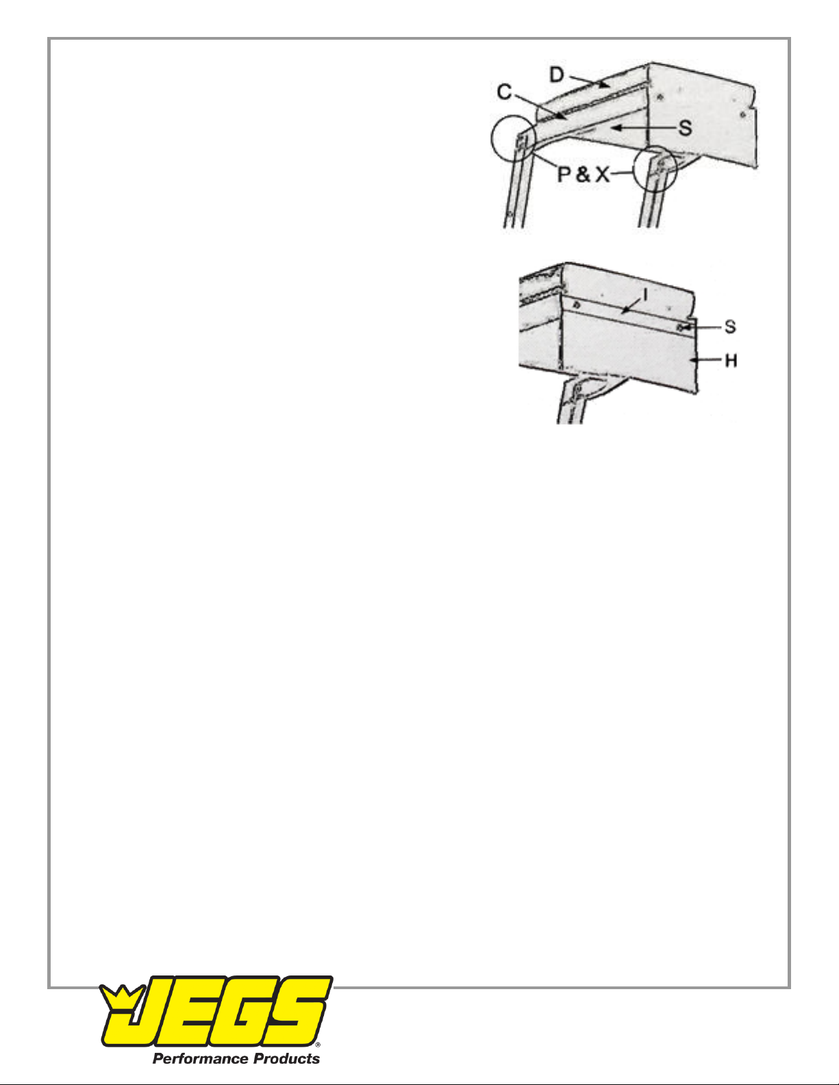
6. Attach the chest deck frame (C) to the top of the ladder assembly
(B) using three chest frame bolts (P) and lock nut 3s (X) on each
side. Attach the chest deck pad (D) using two Phillips screws (S)
from underneath.
7. Place the pouch bracket (l) over the pouch (H) and align the screw
holes. Insert a Phillips screw (S) through the screw holes. Line up the
protruding screws with the holes in the deck frame's front. Secure the
pouch to the deck frame with screws.
8. Place the foam bumper pads (L) over each of the angle support arms and the ladder assembly's crosspiece. This will
prevent the ladder from scuffing the vehicle.
9. Re-check and tighten all bolts and screws as necessary.
CARE & MAINTENANCE
1. Maintain the tool with care. A tool in good condition is efficient, easier to control and will have fewer problems.
2. Inspect the tool components periodically. Repair or replace damaged or worn components. Only use identical
replacement parts when servicing.
3. Maintain the tool's labels and name plates. These carry important information.
WARNING! Only qualified service personnel should repair the tool. An improperly repaired tool may present a
hazard to the user and/or others.
CLEANING
Wipe clean as needed. Use mild upholstery cleaner (not caustic) to clean the chest deck pad as needed.
LUBRICATION
DO NOT lubricate casters. This can damage the mechanism.
STORAGE
1. Remove the leg lock pins from each leg. Hold the ladder when removing the second pin as the base frame will fall to
the floor. Store the pins in the creeper's pouch.
2. Push the ladder's angle support arms back towards the ladder.
3. Lift each leg up until it rests next to the ladder assembly.
4. Store the creeper vertically. Make sure the rear casters are locked once it is in place.
1-800-345-4545 jegs.com

REMOVAL FROM STORAGE
1. Lower each leg.
2. Pull the ladder's angle support arms forward to settle in a height adjustment notch.
3. Remove the leg lock pins from the pouch.
4. Lift the base frame and push the leg down until it the bolt holes align. Push the leg lock pin through and turn the end
down. Repeat with the other leg.
5. Unlock the rear casters and it is ready for use.
DISPOSAL
Recycle a tool damaged beyond repair at the appropriate facility.
1-800-345-4545 jegs.com
Table of contents


