Jehnert 75112 User manual

20.09.10 08:29
Seite 1 von 8
Installation Instructions Product-Ident: 75112
doorboards with soundsystem, Golf V, only 2-doors
Technical Details:
Car Features: electrical window controls, only 2-doors
Model/Year: Golf 5 (06.2003)
Setup-Advice: To reach the best performance, the setup of the
radio (Bass, Loudness etc.) should be null or
neutral.
recommended amplifier power: from 2x 150 - 300 Watt / 4 Ohm
Parts list:
1x Doorboards (right+left) VW golf 5 - only 2doors, covered
1x grills (right+left) VW golf 5- only 2 doors, cover: acoustic fabric
2x XE 26 - Neodymium-Tweeter ø 26mm
(1")
incl. mounting device, Hex nut M4, washer ø 12mm
2x XM 110 - High-End-midrange driver, ø 100mm
(4"),
incl. adapter ring
8x XM 165 - Low midrange driver, power woofer ø 165mm
(6,5")
1x serial wire set for woofers (right + left)
1x 3-way frequency crossover (right+left) VW Golf V 2-doors - part.no 75112
1x Hardware bag, VW Golf V 2-doors - part.no 75112/71112
5x flat head srew M4 x 20
2x flat head srew M4 x 30
1x flat head srew M4 x 40
1x flat head srew M4 x 50
22x hex nut M4
6x sheet metal nut 4,2mm
4x spax screw 5 x 60
2x spax screw 5 x 70
6x washer 12mm
16x washer 20mm
Garantee:
We grant a manufacturers guarantee of 2 years starting from the date of purchase of the doorboard or sound system from the dealer. Within this
guarantee period to our choice we either repair or replace free of charge all defects due to material or workmanship. Exempt from this guarantee
are damages due to improper use, wear and tear or damages which have to be led back on wear or interventions by third parties. The guarantee
does not cover subsequent damages or such defects that only insignificantly impair the value or the usability of the doorboard/sound system. The
guarantee does not cover damages due to external influences. Doorboards with additional or wrong assembly drill holes cannot be returned. These
are damages to the doorboard which cannot be repaired again.
20.09.10 08:30
Seite 2 von 8
Installation Instructions Product-Ident: 75112
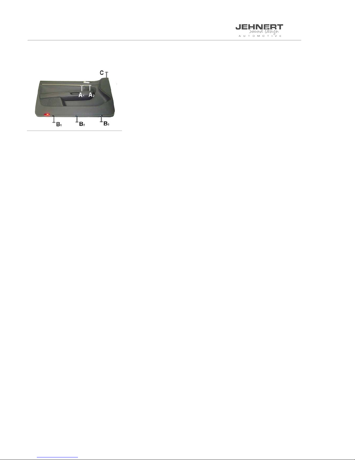
1 Disassembly of the door card
1.1 Roll down window completely.
1.2 Unclip the door handle and unscrew the 2 screws underneath (A1 + A2).
1.3 Remove the 3 screws (B1 - B3) on the bottom side of the door card.
1.4 Unscrew the screw on the mirror triangle C.
1.5 Unclip the door card all around - start on the mirror triangle - and move it upward away.
1.6 Remove the Bowden pull wire of the door latch lever.
1.7 Unplug switch for electric window control.
1.8 Disconnect the original loudspeaker plugs and dismount the original speaker.
20.09.10 08:30
Seite 3 von 8
Installation Instructions Product-Ident: 75112
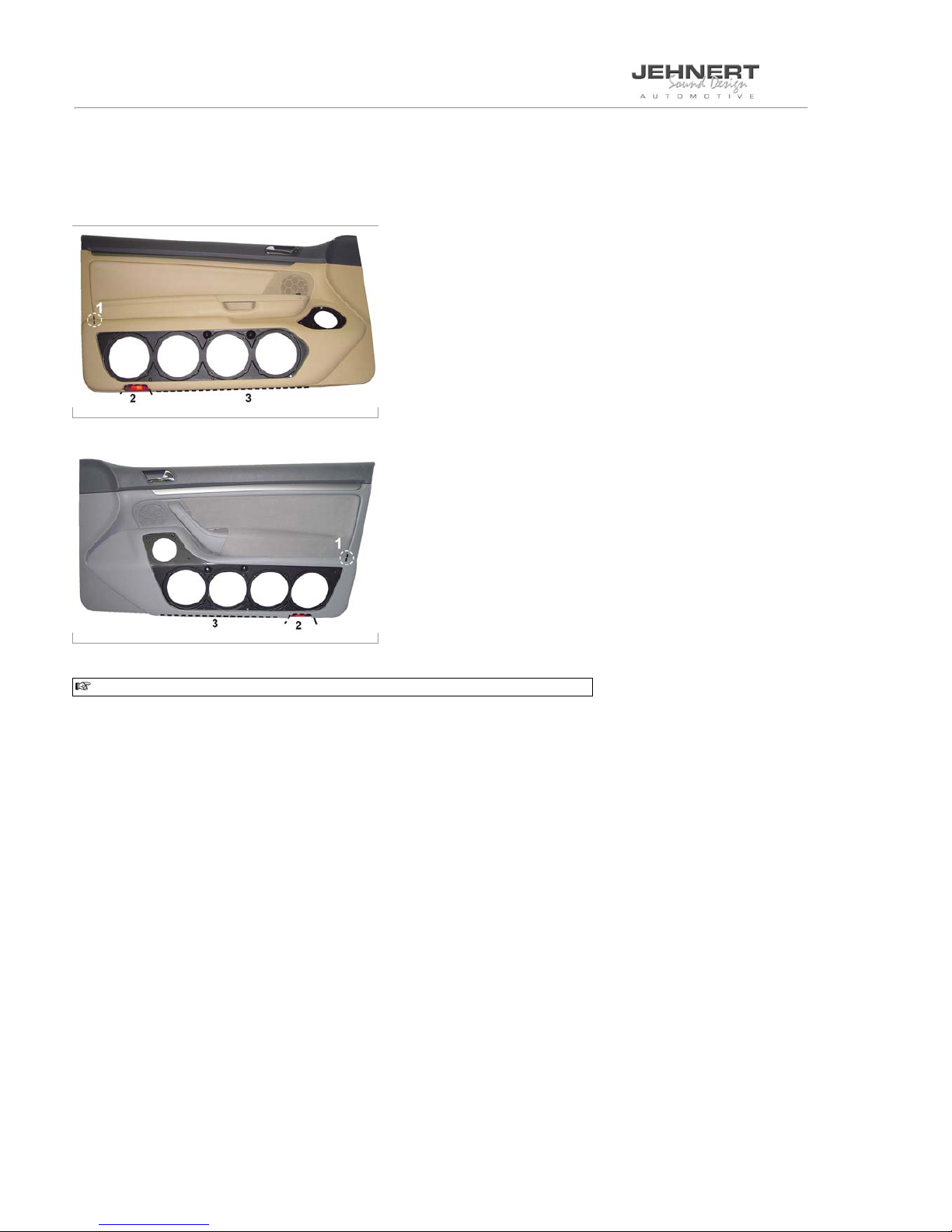
2 Handling of door card: Doorboard alignment
2.1 Place the door card on a plane surface.
2.2 Dismount the loudspeakers attached to the doorboard for transport protection --> retain the screws for later assembly.
2.3 Place the doorboard without speakers on the door card and align it:
drivers side
co-drivers side
Only precise alignment of the doorboards with the door card warrants optimal fit!
Reference points for alignment:
Reference point 1:
Adjust the “nose” on the end of the doorboard directly on the notch of the door card.
Reference point 2:
Align the recessed part on the doorboard with the entrance light.
Reference line 3:
The lower edge of the doorboard is flash with the lower edge of the door card.
Control-Reference point:
The front edge of the doorboard aligns with the design line of the door card.

20.09.10 08:30
Seite 4 von 8
Example
Example
Installation Instructions Product-Ident: 75112
3 Handling of door card
3.1 Use the doorboard as template in order to mark fastening points and cut-outs:
Precisely align the doorboard to the fixing points of the door card.
4 Marking fastening points
driver's side
4.1 Mark the fixing points 1-6_ premounted in the doorboard:
Pressing the doorboard onto the door card leaves a visible impression of the screws - the fastening positions of the
door card.
Marking of the pre-drilled fastening points 7-14:
Use a thin awl to set the marks on the door card.
co-driver's side
4.2 Mark the fixing points 1-7_ premounted in the doorboard:
Pressing the doorboard onto the door card leaves a visible impression of the screws - the fastening positions of the
door card.
Marking of the pre-drilled fastening points 8-14:
Use a thin awl to set the marks on the door card.
20.09.10 08:30
Seite 5 von 8
Example
Example
Example
Installation Instructions Product-Ident: 75112
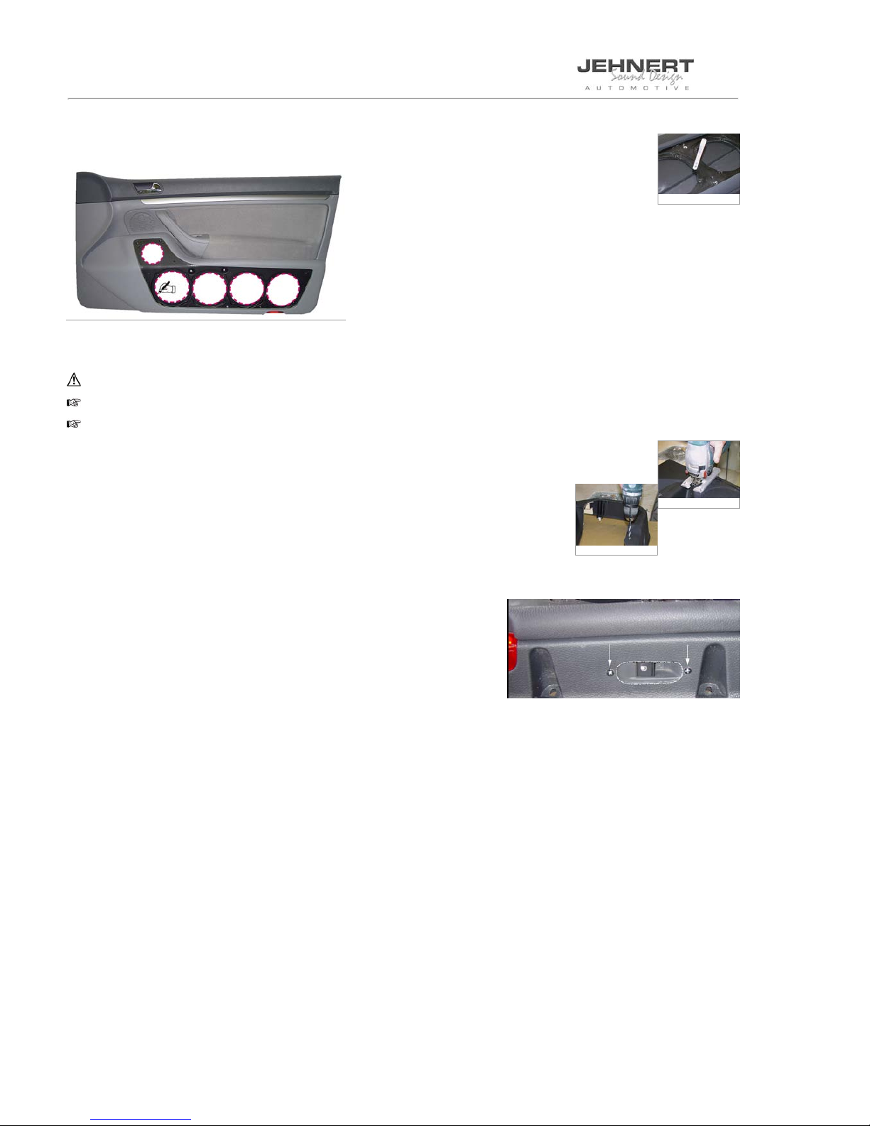
5 Handling of door card cut-outs
The cut out behind the speakers are providing the required full volume of the car door:
5.1 Mark the cut outs for the woofers on the door card. Enlarge them approx. 1cm (= approx. outer diameter of the woofers)
5.2 For a plane alignment of the doorboard also mark the overlapping tray for the cut-out.
IMPORTANT! Check all cut-outs marked:
The fastenings of the doorboard must have to be screwed with the door card!
The fastenings of the door card must not be removed!
5.3 Remove the doorboard again and cut out the positions marked on the door card. Use a compass saw.
5.4 Drill the bore holes for the Spax-screws according to the marks set before - use a 5mm drill
5.5 Drill the bore holes for the M4-screws according to the marks set before - use a 4mm drill
and enlarge to 7-8mm
6 Installation of the switch for the filler unloading device
We recommend to install the switch for the filler unloading on the bottom side of the
door card.
6.1 Mark the open part, cut it out and affix the switch with 2 M4-screws.

20.09.10 08:30
Seite 6 von 8
Example
Installation Instructions Product-Ident: 75112
7 Fastening doorboard
7.1 Screw in the screws supplied with. Affix the doorboard to the door card.
Screw all screws only hand-tight . Secure all M4-screws with washers and nuts, Spax-screws with sheet metal nuts.
TIP: Treat the screw thread with a liquid for screw-in type fuse. (Speaker vibrations may loosen the screws after
some time).
drivers side
co-drivers side
7.2 Check the length of screws and staybolts:
In order to avoid damages to the car door, check all length of the staybolts / screws on the backside of the door card once again
and possibly shorten staybolts or change screws.
7.3 Check again for precise fit and tighten the screws.
All cutting edges of the doorboard must fit to the door card snugly all around without gap!
8 Tweeter installation mirror triangle - original mount without mounting device
8.1 Dismount the mirror triangle and original tweeter. Unplug the connecting cable (the original connecting cables and the tweeter
will not be used any more)
8.2 Adjust the tweeter in the original mounting device. Affix all around with hot melt adhesive or silicone.
8.3 Adapt the JEHNERT-tweeter cable with the speaker cable (1,5-4 qmm) - length of cable up to where the
crossover is installed in the doorboard.
In order to avoid vibration noise insulate all cables with insulating tape e.g.
8.4 Reinstall the mirror triangle.
20.09.10 08:30
Seite 7 von 8
Example
Installation Instructions Product-Ident: 75112
9 Adaptation amplifier - crossover circuit / Insulation of the car doors
9.1 Carefully remove the moisture protection foil.
9.2 Insulation of the car doors - Important tips against vibration-noise (see attached installation recommendation)
9.3 Adaptation amplifier - crossover circuit:
Lead 1x speaker cable (1,5 - 4 qmm) from amplifier to the crossover circuit:
mount of crossover circuit: car door / behind the doorboard
In order to avoid vibration noise secure all cables with insulating tape e.g.
9.4 Reinstall the moisture protection foil to fit precisely.
9.5 For the bass performance the speakers are using the volume of the car door:
Place the door card on the car door as template and mark the position for the woofers
on the inner door metal. Take away the door card and cut out the outlines (approx.
one third of the membrane surface) to reach a better coupling with the door volume.
10 Insulation of the back side of the door card
In order to avoid vibration noise insulate all cables with insulation tape e.g.
10.1 Insulate the backside of the door card e.g. with self-adhesive vibration suppressing insulation
fleece – see attached installation recommendation.
ATTENTION / danger ! No insulation behind the side-airbags!
IMPORTANT:
No insulation material behind loudspeaker, door latch lever and fastening points of the
door card!
11 Installation of the door card onto the car doors
11.1 Check up length of the screws and bolts:
In order to prevent damages of mechanic parts of the car doors, please check once again the length of all bolts and screws on the
back side of the door card! No touch with any mechanic parts of the car doors!
(please shorten if necessary)
11.2 Put the door card into the upper sealing of the car door.
11.3 Fit the door card in contrary order of succession.
Final inspection after installation of the door card:
Please check all functions of the operating elements such as seat adjustment, opening of the glove box, window winder
etc.
20.09.10 08:30
Seite 8 von 8
Installation Instructions Product-Ident: 75112
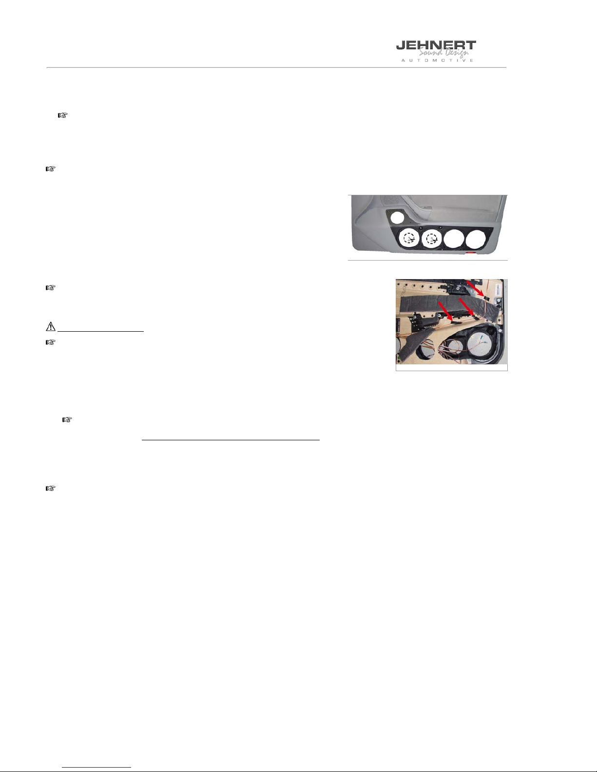
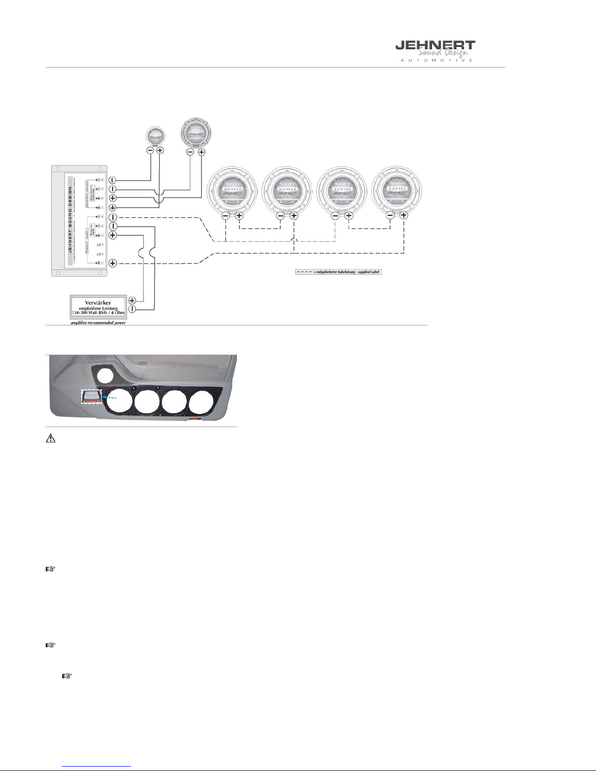
12 Installation of crossover circuit
12.1 Precable crossovers - see wiring diagram.
12.2 Install crossover – without housing; covered with foamed material - in the hollow space between doorboard and door card (see
fig.) and ensure precise fit.
*Important:
Protect the sheet bar against humidity and observe that the sheet bar does not touch any metal parts – danger of short
circuit!
12.3 Connect all speakers to the crossover circuit according to the wiring diagram: Series connection in parallel - cables supplied
with -
12.4 Insert woofer and midrange.
12.5 Notice: You should check the polarity of all woofers after having connected them to the crossover circuit with a 9 volt battery
(input cable on the side of the amplifier):
pole of the crossover circuit input +to +of a 9 Volt battery
pole of the crossover circuit input -to -of a 9 Volt battery
All woofers must move uniformly!
Wrong polarity of a woofer can totally equalize the bass sound!
13 Installation of the doorboard grills
13.1 Carefully press grill with Velcro fasteners onto the doorboards:
IMPORTANT: The Velcro fasteners stick very strongly!
Therefore only press the grills to the doorboard at the end of the installation of the doorboard and the soundsystem!
13.2 Further tips see attached installation recommendation.

Insulation of the door lining
Attention / Danger !!!
No insulation behind
the side-airbags ( g. “B”)
☞Important:
No insulation material behind
- loudspeaker
- door latch lever
- drill ahole for the installation clip ( g. A)
Important tip:
the use of woofer in the door lining may cause vibrations which lead to annoying rattle noises in the car door
!
fi g.: example of a car door
Preventive measurements against vibration noise:
• use our self-adhesive insulation fl eece (art.no.: 27000) or a foam material for
the backside of the door lining (see fi g. above) or
• stabilize the backside of the door lining by means of a special material
(Glass Fibre Filler or stiffening material)
important: keep the cut-outs for the door-airbags and speakers open
• affi x the *backside of the inner door metal with self-adhesive asphalt mats (see fi g. * )
• by knocking on the car door, vibrations caused by mechanic parts (e.g. Bowden pull wire etc. )
and wiring harness may be found out. Cover these parts with foamed material, felt or
something like that
• cut off overlapping cable tie (rattle noise)
• adhere felt or foamed material under the original wiring harness
front side of
inner door metal
door metal outside
= back side of the
inner door metal
moisture protection foil
fi g.: example of a car door

Installation of the speaker’s grill
Precisely align and carefully press grill into the Velcro fasteners.
The Velcro fastener makes a crackling sound when it is closed correctly.
Our Tip:
If the panel cannot be pressed on completely at some points. . .
Cause: the special form at these points and the resulting differences inmaterial cross section of the grill.
Solution: the distance can be levelled out with spacers 3 under the Velcro disc.
(Spacers included with the screw kit)
6. Removing the grills:
The Velcro fasteners stick together very strongly! The grills can be removed anytime by carefully lifting them off.
Please, avoid any way of forceful yanking at the grills. It could break!
☞
Self-help and fault diagnosis
The following notes serve to help troubleshoot and eliminate faults or malfunctionson your own. If the follow-
ing measures are not effective, please call us. Info-Hotline Tel. 0049-7158/95699-0
What can it be if ... possible cause/ solution
..it doesn’t sound right · wrong polarity on the subwoofers (see „speaker connection“)
· crosover circuit attached wrong (see „wiring diagram speaker connection“)
· door lining and moisture protection foil not cut out
(see. „installation of teh door lining“ and „installation of the speakers grill“)
·ampilierdoesn’thaveenoughpower(see.„technicaldetails“)
·amplierconnection
...it doesn’t t correctly · door panel customization (see „handling of the door lining“)
· installation of the panels on the door lining
.....grills do not hold observe notes (see „installation of the speakers grill“)
vibrations observe notes (see „insulation of the door lining“)
②self-adhesive Velcro-strip
①Velcro fastener
③Washer M4 ø 20 as spacer
Other Jehnert Car Stereo System manuals


Popular Car Stereo System manuals by other brands


Trust
Trust HS-8200 quick start guide

Hyundai Mobis
Hyundai Mobis AM943DMAN user manual

Sony
Sony CDX-565MXRF Operating Instruction correction: multi-session... operating instructions

Pioneer
Pioneer SCU 2556 ZRN quick start guide

Boss Audio Systems
Boss Audio Systems BV6654B user manual

Motorola
Motorola 9SMV Service manual