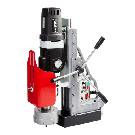
JEI MAGBEAST HM200T User manual

MAGBEAST HM200T
2 | P a g e
CONTENTS OF THE MANUAL.
Page
[1]
SPECIFICATIONS FOR MAGBEAST HM200T
4
[2]
SAFETY PROCEDURES
4
[3]
OPERATING INSTRUCTIONS
5
[4]
EXTENSION CABLE SELECTION
5/6
[5]
MOUNTING OF CUTTERS
6
[6]
TOUBLE SHOOTING GUIDE FOR DRILLING HOLES
7/8/9
[7]
SPEED SELECTION
10
[8]
OVERLOAD PROTECTION
10
[9]
CIRCUIT & CONNECTION WIRING DIAGRAM
11
[10]
GIB ADJUSTMENT -- Patented
12
[11]
PART LIST
13/14/15/
16/17
List of Contents with Magbeast HM200T Drilling Machine
Check
List
1
Operator's Manual
YES/NO
2
Coolant Bottle
YES/NO
3
Arbor—MT5 (1 1/4" bore)
YES/NO
5
6mm Hexagon Key
YES/NO
6
Drill Drift
YES/NO

MAGBEAST HM200T
3 | P a g e
[1] SPECIFICATIONS OF MAGBEAST HM200T DRILLING MACHINE
Maximum hole cutting capacity in .2/.3C steel = 200mm dia. x 75mm deep
Tapping up to M52
Motor Unit
Voltages
230v/60Hz 110v/50-60Hz
Normal full load output
2850 W
Magnet Size
295 x 140 x 70 mm
Magnet Force at 20°C with
25mm minimum plate thickness
The use on any material less than 25mm thick will
progressively reduce the magnetic performance. If
possible, substitute material should be positioned
under the magnet and work piece to equate to a
suitable material thickness. If this is not possible, an
alternative secure method of restraining the machine
MUST be used.
2,200kg/26,800N
Overall Dimensions
Height - maximum extended
955mm
Height - minimum
730mm
Width (including Hand wheel)
280mm
Length Overall (including Guard)
455mm
Stroke
330mm
Net Weight
52kgs
Maximum hand/arm vibration magnitude
(measured at handle during operation in
accordance with ISO5349, using a 22mm cutter
through 13mm MS plate)
0.82 m/s²
Estimate of likely daily vibration exposure.
Operation 30 holes @ 2 minute/hole.
0.29m/s² A(8)
Average noise level during cutting at operator’s
ear position.
89dB(A)

MAGBEAST HM200T
4 | P a g e
READ BEFORE USING THE MACHINE
[2] SAFETY PROCEDURES
● When using electrical tools, basic safety precautions should always be followed to reduce the risk of
electric shock, fire, and personal injury.
● Do NOT use in wet or damp conditions. Failure to do so may result in personal injury.
● Do NOT use in the presence of flammable liquids or gases. Failure to do so may result in personal
injury.
● ALWAYS SECURE THE MACHINE WITH THE SAFETY CHAIN WHEN WORKING VERTICALLY OR OVERHEAD
BEFORE STARTING TO OPERATE.
● Always wear approved eye and ear protection when the equipment is in operation. Failure to do so
may result in personal injury.
● Disconnect from the power source when changing cutters or working on the machine.
● When changing cutters, or removing swarf, ALWAYS wear approved gloves.
● ALWAYS ENSURE CUTTER RETAINING SCREWS ARE SECURE –they sometimes vibrate loose when the
machine is in continuous use.
● Regularly clear the work area and machine of swarf and dirt, paying particular attention to the
underside of the magnet base.
● With a gloved hand, and after switching off, remove any swarf which might have gathered around the
cutter and arbor before proceeding with the next hole.
● Before operating the machine, always remove tie, rings, watches, and any loose adornments which
might entangle with the rotating machinery.
● Should the cutter become 'fast' in the work piece, stop the motor immediately to prevent personal
injury. Disconnect from the power source and turn the arbor to and fro. DO NOT ATTEMPT TO FREE THE
CUTTER BY SWITCHING THE MOTOR ON AND OFF.
● If the machine is accidentally dropped, always thoroughly examine the machine for signs of damage
and check that it functions correctly before trying to drill a hole.
● Regularly inspect the machine and check that nuts and screws are tight.
● Always ensure when using the machine in an inverted position that only the minimum amount of
coolant is used and that care is taken to ensure that coolant does not drip on to the motor unit.
● On completion of the cut, a slug will be ejected. DO NOT operate the machine if the ejected slug may
cause injury.

MAGBEAST HM200T
5 | P a g e
[3] OPERATING INSTRUCTIONS
● Keep the inside of the cutter clear of swarf. It restricts the operating depth of the cutter.
● Ensure that the coolant bottle contains sufficient cutting oil to complete the required operating
duration. Refill as required.
● Occasionally depress the pilot to ensure cutting fluid is being correctly metered.
● To start the machine, first switch on the magnet. And then start the motor by pressing the GREEN start
button.
● Apply light pressure when commencing to cut a hole until the cutter is introduced into the work
surface. Excessive pressure is undesirable, it does not increase the speed of penetration.
● Always ensure that the slug has been ejected from the previous hole before commencing to cut the
next.
(Right) (Wrong)
● Always cut overlapping holes as illustrated above –do not use excessive pressure and ensure cutting
fluid is reaching teeth of the cutter.
● If the slug sticks in the cutter, move the machine to a flat surface, switch on the magnet and gently
bring the cutter down to make contact with the surface. This will usually straighten a cocked slug and
allow it to eject normally.
● Cutter breakage is usually caused by insecure anchorage and a loosely fitting slide. (Refer to routine
maintenance instructions).
[4] EXTENSION CABLE SELECTION
The machines are factory fitted with a 2-meter length of cable having three conductors 1.5mm² LIVE,
NEUTRAL and EARTH.
If it becomes necessary to fit an extension cable from the power source, care must be taken in using a
cable of adequate capacity. Failure to do so will result in a loss of traction by the magnet and a
reduction of power from the motor.
Assuming a normal AC supply of the correct voltage, it is recommended that the following extension

MAGBEAST HM200T
6 | P a g e
lengths shall not be exceeded:
For 110v supply: 3.5metres of 3 core x 1.5mm²
For 230v supply: 26metres of 3 core x 1.5mm² or
17metres of 3 core x 1.0mm²
ALWAYS DISCONNECT THE MACHINE FROM THE POWER SOURCE WHEN CHANGING CUTTERS.
[5] MOUNTING OF CUTTERS
The machine has been made to accept MT5 Arbor.
The following procedure is to be used when mounting cutters.
- Take appropriate pilot and place through hole in shank of cutter.
- Insert shank of cutter into 1 1/4" bore of arbor, ensuring alignment of two drive flats with socket
screws.
- Tighten both screws using hexagon key.

MAGBEAST HM200T
7 | P a g e
[6] Trouble Shooting Guide
Problem
Cause
Remedy
1) Magnetic
base won’t hold
effectively
Material being cut may
be too thin for efficient
holding of magnet.
Attach an additional piece of
metal under work-piece where
magnet will be located, or
mechanically clamp magnetic
base to work-piece
Swarf or dirt under
magnet
Clean magnet
Irregularity on magnet
face or work-piece
Use extreme care, file only
imperfections flush to surface
Insufficient current going
to magnet during drilling
cycle
Confirm power supply and
output from control unit.
2) Cutter skips
out of
center-punch
mark at initiation
of cut
Magnetic base is not
holding effectively.
See causes and remedies above.
Too much feed pressure
at start of cut.
Light pressure until a groove is
cut. The groove then serves as
a stabilizer.
Cutter is worn, chipped
or incorrectly sharpened
Replace or re-sharpen.
Sharpening service is available.
Poor Centre-punch mark;
weak pilot spring; pilot
not centered in
centre-punch mark.
Improve centre-punch and/or
replace worn parts.
Worn or bent pilot, worn
pilot hole
Replace parts.
3) Excessive
drilling pressure
required.
Incorrectly re-sharpened,
worn or chipped cutter
Re-sharpen or replace
Coming down on swarf
lying on surface of
work-piece
Clean work-piece.
Take care not to start a cut on
swarf
Gibs out of adjustment
or lack of lubrication
Lubricate gib and/or adjust grub
screws
Swarf accumulated
(packed) inside cutter
Clear cutter
Incorrect speed selection.
Select appropriate speed.
4) Excessive
Steel swarf or dirt under
Remove cutter, clean part

MAGBEAST HM200T
8 | P a g e
cutter breakage
cutter
thoroughly and replace
Incorrectly re-sharpened
or worn cutter
Always have a new cutter on
hand to refer to for correct tooth
geometry, together with
instruction sheet
Cutter skipping
See causes and remedies (2)
Slide-ways need
adjustment
Tighten slide-way
Cutter not attached
tightly to arbor
Retighten
Insufficient use of cutting
oil or unsuitable type of
oil
Fill arbor with an oil of light
viscosity and check to be sure oil
is being metered into cutter when
pilot is depressed. If not,
check pilot groove and arbor
internally for dirt or apply oil
externally.
Even a small amount of oil is very
effective.
Incorrect speed selection.
Select appropriate speed.
5) ) Excessive
cutter wear
Incorrectly re-sharpened
cutter.
Refer to instructions and a new
cutter for proper tooth geometry
Insufficient or spasmodic
cutting pressure
Use sufficient steady pressure to
slow the drill down. This will
result in optimum cutting speed
and chip load.

MAGBEAST HM200T
9 | P a g e
[7] SPEED SELECTION—Speed Adjustable with volume switch
1. Method of Gear Change
The machines are equipped with a mechanical four-speed gearbox.
Please just turn the lever to the right or left to change gear.
It is not necessary to set the gear in neutral to change gear.(patented)
2. Gear Selection
1st40/60
2nd90/130
3rd170/240
4th380/545
--NO LOAD RPM of each gear--
[8] OVERLOAD PROTECTION
HM200T-200 is extreme heavy duty machine. So it has electronic overload protection
system for unexpected over-torque during drilling or tapping.
Nomally the sensor is set at 14~15A at factory. But if necessary it can be adjusted.

MAGBEAST HM200T
10 | P a g e
[9] CONTROL PANEL

MAGBEAST HM200T
11 | P a g e
①MAGNET SWITCH: Main switch of Machine
②SPEED :
- HI: GEAR RPM
- LO: Electronic RPM, About 75% of HI
③ROTATION SWITCH
- FOR: Forwarding (CW: Clockwise)
- REV.: Reverse (CCW: Counter Clockwise)
[10] PROTECTION-GEAR SLIP
HM200T has a slip system for protection.
against overload in cutters at first gear.
Adjust the torque of LOCK NUT
with torque wrench.
Normally HM200T is set at 80 Nm

MAGBEAST HM200T
12 | P a g e
[11] CIRCUIT & CONNECTION WIRINGDIAGRAM
1. CIRCUIT
WARNING - THIS APPLIANCE MUST BE EARTHED!
Insulation Resistance Test
With the magnet switch in the ON position, apply a voltage of 1.5kv between the live
connection on the mains plug and the frame of the machine for a duration of 7 seconds.
The reading obtained should not fall below infinity. Should a fault be indicated, it must be
found and rectified.
[12] GIB ADJUSTMENT
1. New Sliding System: Machines have a very advanced and stable sliding system. It
consists of three main parts: Slide Board, Precisely Ground Bar &Adjustment Gib.
It has a very wear-resistant structure and keeps first condition as time goes on. It
helps to cut comparatively bigger holes easier than normal dove-tail system without
any bad movement in sliding area.
2. Gib Adjustment: Adjust the Gib using side bolts loose or tight, if necessary.

MAGBEAST HM200T
13 | P a g e
[13] PART LIST
PART A

MAGBEAST HM200T
14 | P a g e
NO.
PART NO.
PART NAME
Q'ty
1
HM200T
A01
SPINDLE
1
2
HM200T
A02
BALL BEARING 6910ZZ
2
3
HM200T
A03
OIL SEAL
1
4
HM200T
A04
MAIN GEAR
1
5
HM200T
A05
BALL BEARING 6906 2RSC3
1
6
HM200T
A06
SNAP RING
1
7
HM200T
A07
PIN
2
8
HM200T
A08
GEAR BOX
1
9
HM200T
A09
NEEDLE BEARING NK 1012
1
10
HM200T
A10
FIRST GEAR
1
11
HM200T
A11
FIRST GEAR M
1
12
HM200T
A12
SNAP RING
1
13
HM200T
A13
FIRST CLUTCH
1
14
HM200T
A14
FIRST PINION
1
15
HM200T
A15
SNAP RING
1
16
HM200T
A16
FIRST GEAR L
1
17
HM200T
A17
SNAP RING
1
18
HM200T
A18
BEARING 6800ZZ
2
19
HM200T
A19
SNAP RING
1
20
HM200T
A20
FIRST CHANGE BLOCK
1
21
HM200T
A21
SOCKET BOLT M3
4
22
HM200T
A22
GEAR CHANGE KNOB
2
23
HM200T
A23
PIN Ф3*8L
2
24
HM200T
A24
GUIDE BRACKET
2
25
HM200T
A25
SNAP RING
2
26
HM200T
A26
GUIDE PIN
2
27
HM200T
A27
INNER COVER
1
28
HM200T
A28
NEEDLE BEARING NK 1012
1
29
HM200T
A29
SNAP RING
1
30
HM200T
A30
SECOND PINION
1
31
HM200T
A31
KEY
1
32
HM200T
A32
SECOND GEAR L
1
33
HM200T
A33
SNAP RING
1
34
HM200T
A34
BEARING 6902 ZZ
2
NO.
PART NO.
PART NAME
Q'ty

MAGBEAST HM200T
15 | P a g e
35
HM200T
A35
NEEDLE BEARING RLM1416
1
36
HM200T
A36
SNAP RING
1
37
HM200T
A37
THIRD GEAR H
1
38
HM200T
A38
THIRD CLUTCH
1
39
HM200T
A39
THIRD PINION
1
40
HM200T
A40
SNAP RING
1
41
HM200T
A41
THIRD GEAR L
1
42
HM200T
A42
SNAP RING
1
43
HM200T
A43
BEARING 16001 ZZ
2
44
HM200T
A44
THIRD CHANGE BLOCK
1
60
HM200T
A60
BEARING 6202 2RSC3
1
61
HM200T
A61
SNAP RING
1
62
HM200T
A62
FAN GUIDE
1
63
HM200T
A63
ARMATURE ASS'Y
1
64
HM200T
A64
RUBBER BUSHING
1
65
HM200T
A65
BEARING NTN 6201UU
1
66
HM200T
A66
STATOR
1
67
HM200T
A67
MOTOR INNER COVER
1
68
HM200T
A68
MOTOR HOUSING
1
69
HM200T
A69
CARBON BRUSH HOLDER
2
70
HM200T
A70
CARBON BRUSH CAP
2
71
HM200T
A71
SIDE HOUSING COVER
2
72
HM200T
A72
SOCKET BOLT M4
2
73
HM200T
A73
SOCKET BOLT M5
2
74
HM200T
A74
HOUSING CAP
1
75
HM200T
A75
SOCKET BOLT M4
4
76
HM200T
A76
CARBON BRUSH
2
77
HM200T
A77
SOCKET BOLT M4
4
78
HM200T
A78
WIRE COVER
1
79
HM200T
A79
CABLE GRAND ASS’Y
1
80
HM200T
A80
SOCKET BOLT M6
4

MAGBEAST HM200T
16 | P a g e
PART B

MAGBEAST HM200T
17 | P a g e
``
NO.
PART NO.
PART NAME
Q'ty
1
HM200T
B01
SLIDE
1
2
HM200T
B02
O-RING ASSEMBLED STOPPER BOLT
4
3
HM200T
B03
PIN PI6-L10
4
4
HM200T
B04
HEX SOCKET BOLT M6-L15
5
5
HM200T
B05
ARBOR STOPPER
1
6
HM200T
B06
HEX SOCKET BOLT M5-L10
1
7
HM200T
B07
WING BOLT M8-L20
2
8
HM200T
B08
GIB A
4
9
HM200T
B09
RACK GEAR
1
NO.
PART NO.
PART NAME
Q'ty
10
HM200T
B10
GIB B
2
11
HM200T
B11
RAIL BAR
2
12
HM200T
B12
SLIDE PLATE
1
13
HM200T
B13
HEX SOCKETBOLTM6-L15
8
14
HM200T
B14
MAIN FRAME
1
15
HM200T
B15
SLIDE SECOND PINION
1
16
HM200T
B16
BUSHING 15-15-1.5T
2
17
HM200T
B17
SLIDE SECOND GEAR ASS’Y
1
18
HM200T
B18
SLIDE SECOND PINION COVER
2
19
HM200T
B19
HEX SOCKETBOLT M4-L10
10
20
HM200T
B20
SLIDE FIRST PINION
1
21
HM200T
B21
SLIDE FIRST GEAR
1
22
HM200T
B22
BUSHING 17-15-1.5T
1
23
HM200T
B23
BEARING TA1715Z
2
24
HM200T
B24
SLIDE FIRST PINION COVER
2
25
HM200T
B25
SNAP RING STW-17
2
26
HM200T
B26
HANDLE ASS’Y
3
27
HM200T
B27
HANDLE JOINT ASS’Y
1
28
HM200T
B28
EYE BOLT M10-L20
2
29
HM200T
B29
WIRE HOSE
1
30
HM200T
B30
CABLE GLAND ASS’Y
1
31
HM200T
B31
POWER CABLE
1
32
HM200T
B32
HEX SOCKETBOLT M6-L60
4
33
HM200T
B33
HEX SOCKETBOLT M6-L80
2
34
HM200T
B34
CONTROL PANEL, WITH SWITCH
1
35
HM200T
B35
MAIN PCB
1
36
HM200T
B36
TRUSS HEAD BOLT M4-L10
6
37
HM200T
B37
HEX FLAT BOLT M10-L35
4
38
HM200T
B38
BEARING HK1512
2
39
HM200T
B39
HANDLE FIRST GEAR GUIDE
1
40
HM200T
B40
HEX SOCKETBOLT M6-L25
4
41
HM200T
B41
ELECTROMAGNET
1
42
HM200T
B42
HEX SOCKETBOLT M4-L20
2
43
HM200T
B43
COOLANT TANK BRACKET
1
44
HM200T
B44
COOLANT TANK ASS’Y
1

MAGBEAST HM200T
18 | P a g e
WARRANTY CARD
WARRANTY CARD No.............
..................................................................... in the name of Manufacturer warrants the
Magbeast 5 Drilling Machine with Magnetic Base to be free of defects in material and
workmanship under normal use for a period of 12 months from date of sale.
This warranty does not cover cutters, damage or wear that arise from misuse, accident,
tempering or any other causes not related to defects in workmanship or material.
Date of production.........................................................................................................
Serial number ...............................................................................................................
Date of sale...................................................................................................................
Signature of seller.........................................................................................................
4 / 2nd February 2023
WE RESERVE THE RIGHT TO MAKE CORRECTIONS
AND MODIFICATIONS IN THIS MANUAL WITHOUT PRIOR NOTICE
Table of contents
Other JEI Drill manuals

