Jeil Mtech Co., Ltd. Marksman MK-100N User manual

(MK-100N User Manual)
North America Master Distributor
Mercury Marking Devices
TEL: 800-269-9305
FAX: 951-674-5674
Web-page: www.mercurymarking.com
E-mail: [email protected]
1

Index
(General information)
(Installation)
Function and operation of program
Handling of Keyboard
F1 (M_MANU) MODE
F2 (A_MARK) MODE
F3 (Edit) MODE
F4 (File) MODE
F5 (Setup) MODE
F6 (Test) MODE
F7 (Font & Plt) MODE
F8 (Communication) MODE
Control to the marking machine with a PC
Drawing up of PLT File by AUTO-CADR14
Maintenance and Mending
Supplement
Parts List
2
Thank you for purchasing Jeil M-tech`s CNC DOT PIN Marking Machine
TO maximize the efficiency for operating CNC DOT PIN marking machine, read the details in this manual.
If there are any problems not mentioned in this manual, please inquire us and we will answer you as soon
As possible. Also, if there are any suggestions regarding inconveniences or improvement, please inform us.
The products are constantly upgraded, and we assure you that it will help the equipment maintenance.
TEL 02-406-0015
FAX 02-406-4452
E-MAIL [email protected] (Representative)
[email protected] (Sales)
[email protected] (Technical Support)
WEB SITE www.pinmarking.com
“Marksman “is Jeil-Mitch’s Trade name
The marking pin has a low sound level of less than”60db,”has acquired the patent and registration,
and has been produced since Jan 2000
Marksman is manufactured and confirmed by the Europe CE certification standards “security,
endurance, and electromagnetic wave standards, etc”
The warranty term is 1 year since the delivery date. After a year, the traveling expenses will be billed.
All components are applicable for warranty, with the exception of intentional or accidental defeats.
When a problem occurs during delivery and installation by the dealer, immediately return
the products to the Dealer and get it checked.
Any problems resulting from intentional or accidental mistakes are not applicable for warranty.
3

MARKING HEAD
MK100-115 (Standard type) MK100-115J (Dust cover)
MK200 (Circumference) MK-GUN (Portable)
MARKING CONTROLLER
MCU-100N (New controller) MK-200B
4

Accessories
Common CABLE Cable 15M
CDC-20 Dip switch
New NF-8785 T-300
5

MARKING PIN
LP-06 LP-10 LP-15 PH-16
LP-10 pin for Gun PLP-10 DIA_90D
6

Composition of Marking system
Composition and application of CNC Marking Machine
Jeil Mtech has got certificate that ISO 9001, CE Mark and Many kinds of domestic
Certificates.
Marksman
SD CARD
MCU-100N
KEY BOARD
ON
OFF
www.pinmarking.com
Display
PIN SEL.
PH LP/SC
핀셀렉터스위치
전원스위치
키보드함
LCD화면
SD 메모리카드슬롯
TO_HEAD
I/O COM
OPTION
CPU
RS-232
AC
85~264V/3A
F?G
메인커넥터
I/O포트 이더넷포트(옵션) CPU 포트
전원코드
7

(Installation)
Matters to be attended to before installation
Main source of electricity: AC220Volt, 1ph, 3Ampare
Cable connection: All cables need to be installed by being connected fast without being bent or
Twisted.
Install Punch Head
Installation should take place so that the distance between the Pin and the punching face should be
3.5~4.5mm with a deviation of ±10mm/
Valid marking distance: At PH16, 3.0~5.0mm.At LP10, 5.0~8.0mm
Valid air pressure: At PH16, 4.0kg/cm2~6kg/cm2, At LP10, 2.0kg/cm2~3kg/cm2
Appropriate air pressure: AT PH16, 4.0~4.5kg/cm2, At LP10, 2.5~3.0kg/cm2
Control marking quality: The quality of the marking products differ according to marking distance
and air pressure. At the Parameter Setup of MCU`s F4 screen, you can control the transfer
speed of pin. Also, you can choose the thickness of the pin edge-the Ball type is thick and deep,
the sharp type is thin or deep.
Refer to the drawing below to decide the installation location and the Pin interval.
X축
Y축
0점
ABCDEF
Marking Area
3~5mm 유지
소재
(Reference
1) (Reference2)
#. The closer the marking location is to 0, the operation time gets shorter.
Puncher sound level
In general, the puncher sound increases when the board is thin and the clamp is not steadily attached.
Sound cover attached: 55db, with silencer: under 50db
Puncher with weighty substance in open space: 72db with silencer: 56db
Puncher with a board less than 2 t in open space: 87db with silencer: 68db
Soundproof cover for a board less than 2 t in open space: 65db, with silencer: 50db이하.
8
Please read the following before executing the program
<FUNCTION Keys>
F1: M_MENU (Manual marking mode) indicated the function key of controller.
F2: A_MARK (Automatic marking mode)
Marking mode. Includes status window for the location and produced amount of the block data for the
Puncher.
F3: EDIT (Editing mode)
Edit the marking contents such as font, font size, letter space, Lot number, operation method, and
Direction of the letters.
F4: FILE (File mode)
Convert in order READ->WRITE->ERASE and store the data to S/D card.
F5: SETUP (Adjustment mode of parameter)
Control the speed of the marking pin and motor.
F6: TEST (Test mode)
This mode is to check for the condition of the marking machine and there`s function to store the time,
data, year, month and day.
F7: FONT (User font set up mode)
In that case you want to use another font except for basic font in controller, can be set up into User1~User4 each.
F8: COMM (Communication mode)
Control the operation of the marking machine with a PC.
F9: PREV
If press F9, can move the cursor previous.
F10: NEXT
If press F10, can move the cursor next.
For other keys, Enter key function is the same F10. After adjust the data, must always press the enter
and store. If press the Space bar on the Font and Type section, operation mode is converted.
Direction key is used during when input the data to F4 and move cursor.
When you mark some data, you have to it set F2 screen. When it is “READY”, you can mark.
9
However when you use AUTO CAD file on PC, you have to it set F8 comm. mode.

BLOCK, PATTERN, FILE, MODEL Terms are the same.
The definition of line is the number of rows in each block.
When adjusting and inputting the punched details and conditions and press “Enter”, it inputs
Automatically.
Turn off the MCU for all screens.
Exception) Punching or connecting with the Host, turn the main power off when it works finished.
If you want to erase all of wrong data, please press the “MEMORY Clear “switch and until the power
turn off and on. And you can see the signal “MEMORY CLEAR” on the screen.
“Ground of MCU” connector has to be connected in an automated factory.
Use of the function key
If press the function key, below screen is showed.
F1: M_MENU
F1 : M_MENU F2 : A_MARK F3 : EDIT F4 : FILE
F5 : SETUP F6 : TEST F7 : LOAD F8 : COMM
BLK NO. [ 000 ]
EMT
< NO BLOCK DATA >
MARK_UP_TO[ 00000000 ] UNIT_NO[00001713]
15:15:22 STATUS [ ]
[MANUAL MARK MODE]
BLK_COPY : CTRL_C BLK_MOVE : UP/DOWN
CURSOR_MOVE : ENTER SELECT : SPACE_BAR
F9 : SIMULATION F10 : MARK F11 : HOME
F1 screen is the mode to mark simple manual marking. In that case manual marking, you can mark
something just this screen.
BLK (Block): Block number shall be generated [000] up to [999] automatically and each block number.
You can mark the file in order and change it. And it indicates the location of the file.
(
BLK_COPY: CTRL_C: The function is that copy the some data and input.
BLK_MOVE: UP/DOWN: Select the block
CUSOR_MOVE: ENTER: Moving the cursor and storing the data
10

SELECT: SPACE_BAR: Convert key when you select the mode during data marking
F9: SIMULATION: Test mode (not real marking)
F10: MARK: The function is that copy the data and input.
F11: HOME: The function is that Return to start point. (Same to Reset function)
MARK UP TO: This function allows you to set a number of how many pieces of your product to be marked.
If you set this number as mark up to [00000100] and when reached this number, the system will stop
automatically the marking operation.
UNIT NO. : Indicate the operation quantity until now.
09:30:31: Indicate the present time
STATUS: Indicate the state of marking machine
F1 : M_MENU F2 : A_MARK F3 : EDIT F4 : FILE
F5 : SETUP F6 : TEST F7 : LOAD F8 : COMM
BLK NO. [ 000 ]
LN X : 0300 Y : 0300 A : 000
FNT : STD1 CH:030 PX:030 PAUSE : N
MARK_UP_TO[ 00000000 ] UNIT_NO[00001713]
15:15:22 STATUS [ ]
[MANUAL MARK MODE]
BLK_COPY : CTRL_C BLK_MOVE : UP/DOWN
CURSOR_MOVE : ENTER SELECT : SPACE_BAR
F9 : SIMULATION F10 : MARK F11 : HOME
F2 SCREEN: A_MARK (Automatic marking)
F1 : M_MENU F2 : A_MARK F3 : EDIT F4 : FILE
F5 : SETUP F6 : TEST F7 : LOAD F8 : COMM
BLK NO. [ 000 ]
PLC INPUT SIGNAL [ . . . . . . . . ] [ . . . . . . . . ]
15:15:22 STATUS [ ]
[AUTO MARKING MODE]
F9 : SIMULATION F10 : MARK F11 : HOME
MARK_UP_TO[ 00000000 ] UNIT_NO[00001713]
< CURRENT DATA >
JEIL MTECH
BLK: An indication window display the file that inputted marking data, can input from [000] to [999].
As above the block number it operates in order. Can change the marking order and indicate the file
locate during operating.
11

But in that case operating by PLC BINARY, it marks according to PLC signal.
MARK UP TO: This function allows you to set a number of how many pieces of your product to be marked.
If you set this number as mark up to [00000100] and when reached this number,
the system will stop automatically the marking operation.
EX) MARK UP TO: [00000100] = Marking machine marks the data until 100, and then it outputs alarm signal
From [00000101].
UNIT NO: This menu is a counter. It indicates the marking quantity.
09:30:31: Indicate the present time.
At multimode screen
F1 : M_MENU F2 : A_MARK F3 : EDIT F4 : FILE
F5 : SETUP F6 : TEST F7 : LOAD F8 : COMM
BLK NO. [ 00.00 ]
PLC INPUT SIGNAL [ . . . . . . . . ] [ . . . . . . . . ]
15:15:22 STATUS [ ]
[AUTO MARKING MODE]
F9 : SIMULATION F10 : MARK F11 : HOME
MARK_UP_TO[ 00000000 ] UNIT_NO[00001713]
< CURRENT DATA >
zAccording to mode, each state is shown differently.
<Explanation of multi block mode of F2 screen>
When you get the products at first, F2 screen is to assign single block same as below.
F1 : M_MENU F2 : A_MARK F3 : EDIT F4 : FILE
F5 : SETUP F6 : TEST F7 : LOAD F8 : COMM
BLK NO. [ 000 ]
PLC INPUT SIGNAL [ . . . . . . . . ] [ . . . . . . . . ]
15:15:22 STATUS [ ]
[AUTO MARKING MODE]
F9 : SIMULATION F10 : MARK F11 : HOME
MARK_UP_TO[ 00000000 ] UNIT_NO[00001713]
< CURRENT DATA >
JEIL MTECH
In case of need to several lines marking with only one signal of PLC, though inefficient if give a
Point of contract each to the block. If you make subordinate block to main signal block, you can do
Hard work easily.
12

If you want to use this mode, you make the DIP switch 5 of main board in controller turn off.
F1 : M_MENU F2 : A_MARK F3 : EDIT F4 : FILE
F5 : SETUP F6 : TEST F7 : LOAD F8 : COMM
BLK NO. [ 00.00 ]
PLC INPUT SIGNAL [ . . . . . . . . ] [ . . . . . . . . ]
15:15:22 STATUS [ ]
[AUTO MARKING MODE]
F9 : SIMULATION F10 : MARK F11 : HOME
MARK_UP_TO[ 00000000 ] UNIT_NO[00001713]
< CURRENT DATA >
Like the above screen, it is different from previous working method.
EX) Single block marking Multi block marking
GR 45 [000] Need to 3 points of contact GR45 [00.00] Need to a point of contact
030423 [001] 030423 [00.01]
000012 [002] 000012 [00.02]
When you do the same work like the above, if you work on the general mode, you have to give a point of
contact to each block. But if you do the work on the Multi mode, you don`t need to give several points
of contact to the block. For instance if you give a point of contact to [00.00] block, subordinate block
[00.01][00.02] do the work by itself.
[00.00]: Signal block [01.00]: Signal block [02.00]: Signal block [03.00]
[00.01]: Subordinate block [01.01]: Subordinate block [02.01]: Subordinate block
[00.02] [01.02] [02.02]
[00.19] [01.19] [02.19]
At [00.00], in front of a decimal point means the block address to receive PLC signal and behind means
Subordinate block, therefore you can mark the Maximum 20lines with just 1 electric signal.
F3 SCREEN: EDIT (LINEAR MARKING) SCREEN
13

F1 : M_MENU F2 : A_MARK F3 : EDIT F4 : FILE
F5 : SETUP F6 : TEST F7 : LOAD F8 : COMM
BLK NO. [ 000 ]
LN X : 0300 Y : 0300 A : 000
FNT : STD1 CH:030 PX:030 L:00000000 I:+1
<DATA> PAUSE : N
JEIL MTECH
[EDIT MODE]
BLK_COPY : CTRL_C BLK_MOVE : UP/DOWN
CURSOR_MOVE : ENTER SELECT : SPACE_BAR
BLK NO. [ 001 ]
EMT
< NO BLOCK DATA >
FONT: Select the letter type. (If press the SPACE BAR, Menu was changed.) FONT: Select the letter type. (If press the SPACE BAR, Menu was changed.)
STD1 = Standard font, Normal type STD1 = Standard font, Normal type
STD2 = Gothic style STD2 = Gothic style
DOT = 5*7 DOT style DOT = 5*7 DOT style
User1~User4 = To load user`s own font. User1~User4 = To load user`s own font.
Plt1 = To load AUTO-CAD Files “LOGOS&DRAWING etc”. Plt1 = To load AUTO-CAD Files “LOGOS&DRAWING etc”.
CH: Character size 1.0~8.0mm height CH: Character size 1.0~8.0mm height
PX: Interval between the letter and letter PX: Interval between the letter and letter
L: When user marks the serial number, first number to start. L: When user marks the serial number, first number to start.
EX) (00000010) = First marking serial number is 10 EX) (00000010) = First marking serial number is 10
I: Creation increase and decrease of serial number. I: Creation increase and decrease of serial number.
EX) I: +1 = As the above instance, second marking serial number is 11. EX) I: +1 = As the above instance, second marking serial number is 11.
I: -1 = As the above instance, second marking serial number is 9. I: -1 = As the above instance, second marking serial number is 9.
Ln: Select the marking type Ln: Select the marking type
(Press SPACE BAR and change menu like the below) (Press SPACE BAR and change menu like the below)
Ln: Linear marking. Ln: Linear marking.
Cr: ARC marking Cr: ARC marking
PLT: PLT file marking PLT: PLT file marking
Cy: Marking on the cylindrical surface Cy: Marking on the cylindrical surface
2D: Matrix bar code marking 2D: Matrix bar code marking
X: The width distance from start point to a lower of first letter. X: The width distance from start point to a lower of first letter.
Y: The height distance from start point to a lower of first letter. Y: The height distance from start point to a lower of first letter.
14
F1 : M_MENU F2 : A_MARK F3 : EDIT F4 : FILE
F5 : SETUP F6 : TEST F7 : LOAD F8 : COMM
BLK NO. [ 000 ]
LN X : 0300 Y : 0300 A : 000
FNT : STD1 CH:030 PX:030 L:00000000 I:+1
<DATA> PAUSE : N
JEIL MTECH
[EDIT MODE]
BLK_COPY : CTRL_C BLK_MOVE : UP/DOWN
CURSOR_MOVE : ENTER SELECT : SPACE_BAR
BLK NO. [ 001 ]
EMT
< NO BLOCK DATA >
14

Delicate adjustment of X and Y value on F3 mode.
0152 When press the + 0152
0151 Press + 0151
Ln X:0150 Y:0150 Ln X : 0150 Y : 0150
(After move the cursor like the above ) 0149 Press - 0149
0148 When press the - 0148
Put the cursor on the coordinates [0000] and press + and – on the keyboard.
Then marking pin move by 0.1mm, can modify marking data.
(CAUSE)For storing, you have to press “ENTER”key
A: Marking direction (Choosing the marking direction of angle version)
0
HOME X
Y
ABCD
ABCD
ABCD
A:000
X:0100
Y:0100
A:030
A:060
zYou can create and move you’re marking data toward anyway.
P: P is pause
P: Y = The pin wait for the next signal after marks last letter.
(To wait for next time start signal) Not output END signal
P: N = The pin returns back to home automatically.
DATA SCREEN: Input the data
All letter and font in the keyboard can be used.
EX) JEIL MTECH CO., LTD.
15

Editing the multi line
030401
234567
HD4
X1:100mm
X2:120mm
X3:140mm
Y1:50mm
Y2:75mm
Y3:100mm
X-AXIS
Y-AXIS
5mm(Size)
ZERO POINT
4.8mm(Pitch)
As above, if input the moving distance of X (100mm) and Y (50mm) on the F3: EDIT MODE.
Marking pin is located to HD4 and a datum point is a lower letter.
The other location can be modified as above. If HD4 is a [000] block, [001] block is
03041, [002] block is 234567
F3: Cr mode-ARC marking
F1 : M_MENU F2 : A_MARK F3 : EDIT F4 : FILE
F5 : SETUP F6 : TEST F7 : LOAD F8 : COMM
BLK NO. [ 000 ]
CR X : 0300 Y : 0300 R:000 D : W+
FNT : STD1 CH:030 PX:030 L:00000000 I:+1
<DATA> PAUSE : N
031213
[EDIT MODE]
BLK_COPY : CTRL_C BLK_MOVE : UP/DOWN
CURSOR_MOVE : ENTER SELECT : SPACE_BAR
BLK NO. [ 001 ]
EMT
< NO BLOCK DATA >
ARC marking is nearly similar to Linear marking, however according to a specified radius is marked
by controller. Generally a letter size and all intervals are the same as Linear marking.
16

Y-AXIS
ZERO POINT
X-AXIS
0
3
2
1
1
3
CX:75mm
CY:70mm
Check! Please input the marking data value within the marking area. You have to input the value less
than marking Area. The X/Y coordinates are always smaller than the Radius. If it is wrong, you can see
some signal “LIMIT ERROR” or “DATA ERROR”
R: 0050(RADIUS): When it`s ARC marking, a radius from center to start point of marking
Y-AXIS
3
1
ZERO POINT
CY:70mm
CX:75mm
2
3
0
1
X-AXIS
R:50mm
A: 030(Angle: 30°): Select the marking start degree
3
1
0
3
2
CX:75mm
CY:70mm
1
Y-AXIS
R:50mm
ZERO POINT
X-AXIS
D (Direction): W+ (can select the marking direction)
W +: To move the marking start point the clockwise.
W -: To move the marking start point the counter clockwise.
Key: Press +, - or SPACE BAR
17

CY:70mm
CX:75mm
Y-AXIS
ZERO POINT
R:50mm
1
2
3
0
1
3
X-AXIS
기준점
W-
W+
Check! When W+ and W- are used to mark at once and you want marking
to be marked the same area. You have to select that R value of W- more
Than R value of W+ and letter size of an R value. (Because a datum point
is a lower letter.)
F3 screen: Cy- Cylindrical marking
F1 : M_MENU F2 : A_MARK F3 : EDIT F4 : FILE
F5 : SETUP F6 : TEST F7 : LOAD F8 : COMM
BLK NO. [ 000 ]
CY X : 0300 Y : 0300 R:150 D : X+
FNT : STD1 CH:030 PX:030 L:00000000 I:+1
<DATA> PAUSE : N
ABCD
[EDIT MODE]
BLK_COPY : CTRL_C BLK_MOVE : UP/DOWN
CURSOR_MOVE : ENTER SELECT : SPACE_BAR
BLK NO. [ 001 ]
EMT
< NO BLOCK DATA >
18
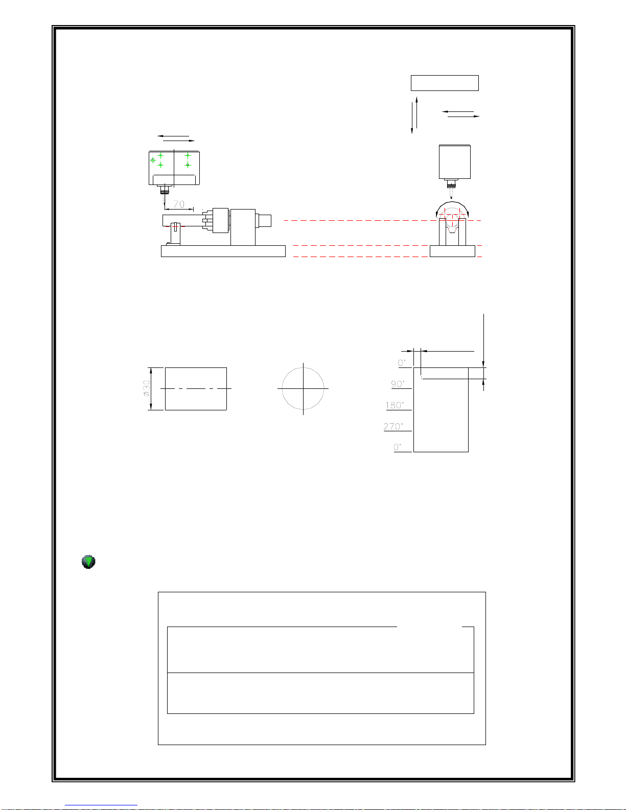
* R: 0150 (Radius of tube) in the index marking
Motor Y-Axis
적용모델: MK-200, MK-073
MK-200 INDEX
X-
X+
Y- Y+
마킹작업 방향
X+
X-
If in this case CH: 050 PX: 050 PX: 050 X: 0100, Y: 0200 D: Y+, you can mark the data
According to circumference.
ABCDE
Y:20.0mm
X:10.0mm
0°
270°90°
180°
ABCDE
봉재료
원주면의 마킹
zD: X+/X- marks the data toward Axis
zD: Y+/Y- marks the data toward circumference
F3 Screen: 2D MATRIX EDIT MODE
F1 : M_MENU F2 : A_MARK F3 : EDIT F4 : FILE
F5 : SETUP F6 : TEST F7 : LOAD F8 : COMM
BLK NO. [ 000 ]
2D X : 0300 Y : 0300 A :000
FNT : STD1 CH:030 PX:030 L:00000000 I:+1
<DATA> PAUSE : N
ABABBAAA
[EDIT MODE]
BLK_COPY : CTRL_C BLK_MOVE : UP/DOWN
CURSOR_MOVE : ENTER SELECT : SPACE_BAR
BLK NO. [ 001 ]
EMT
< NO BLOCK DATA >
19

2D has a good function which store a lot of data more than 1D bar code. 2D is recognized by 2D
reader and 2D can be stored a lot of data. Therefore it is suitable to the mark of the automated line.
In this mode, when it marks the inputted data and number. This mode make them convert to 2D code.
And then marks with a data in the square and store the data.
Being used 2D code on MK-100 is ECC-200,each data is marked by a dot in the square.
It marks like above and a small cell is indicated a Dot.
Below pictures are to recognize the marked data on the engine block by 2D code reader.
[Picture1: Good screen of 2D code] [Picture2: Failure screen of 2D code]
Picture 1 recognizes the 2D code exactly and picture 2 is failure due to moisture, oil and dispersivity.
Because mark of the 2D code use the light and shade of engrave with a dot, if Dot is veiled, it may not be
Recognized. Before use 2D code, remove dispersivity.
20
Table of contents
Popular Industrial Equipment manuals by other brands


RK Rose+Krieger
RK Rose+Krieger RK MonoLine R Assembly instructions

Astrea
Astrea Evolve AB070505 Technical user guide

Axiom
Axiom DMF Series Installation, operation & maintenance instructions

THORLABS
THORLABS MLJ150 Kinesis User Guide

Will Burt
Will Burt 7-30 HDL operating instructions

Siemens
Siemens SIMATIC RTLS4040T operating instructions

Centa
Centa CENTAX-L Assembly and operating instructions

Viessmann
Viessmann VITOBLOC 200 Assembly instructions

Balluff
Balluff BTL5-S1 Series Condensed guide

Branick
Branick 155 Installation & Repair Parts Information

hager
hager univers N Mounting instructions

Westward
Westward 48UJ80 Operating instructions & parts manual