JEM Radio II User manual

JEM Radio II
Operation Guide
Manual P/N M09999-999
2115 Victor Place
Colorado Springs, Colorado 80915
800.284.0399
www.jemcom.com

JEM Radio II
Operation Guide
Table of Contents
Display 3............................................................................................................................................................................
Channel Entry 4.................................................................................................................................................................
Shortcuts 4.....................................................................................................................................................................
Text Messages 4.................................................................................................................................................................
Buttons 5............................................................................................................................................................................
Headset Use 6....................................................................................................................................................................
IP Network Use 6...............................................................................................................................................................
Virtual Control Head 6.......................................................................................................................................................
Secondary Control Head 7.................................................................................................................................................
Menus 8..............................................................................................................................................................................
GENERAL 9................................................................................................................................................................
AUDIO 10....................................................................................................................................................................
NXDN 11.....................................................................................................................................................................
INFO 11.........................................................................................................................................................................
Error Messages 11..............................................................................................................................................................
Cable Connectors 12..........................................................................................................................................................
Remote Control Head Connector (19-Pin) 12...............................................................................................................
Power Connector (4-Pin)!
Rear Handset Connector (6-Pin) 13...............................................................................................................................
Accessories Connector (12-Pin) 14...............................................................................................................................
(Appendix A) 15...............................................................................................................................................................
PLL Frequency lookup table 15.....................................................................................................................................
(Appendix B) 16...............................................................................................................................................................
(Appendix E) 17.................................................................................................................................................................
2
JEM Radio II
Operation Guide
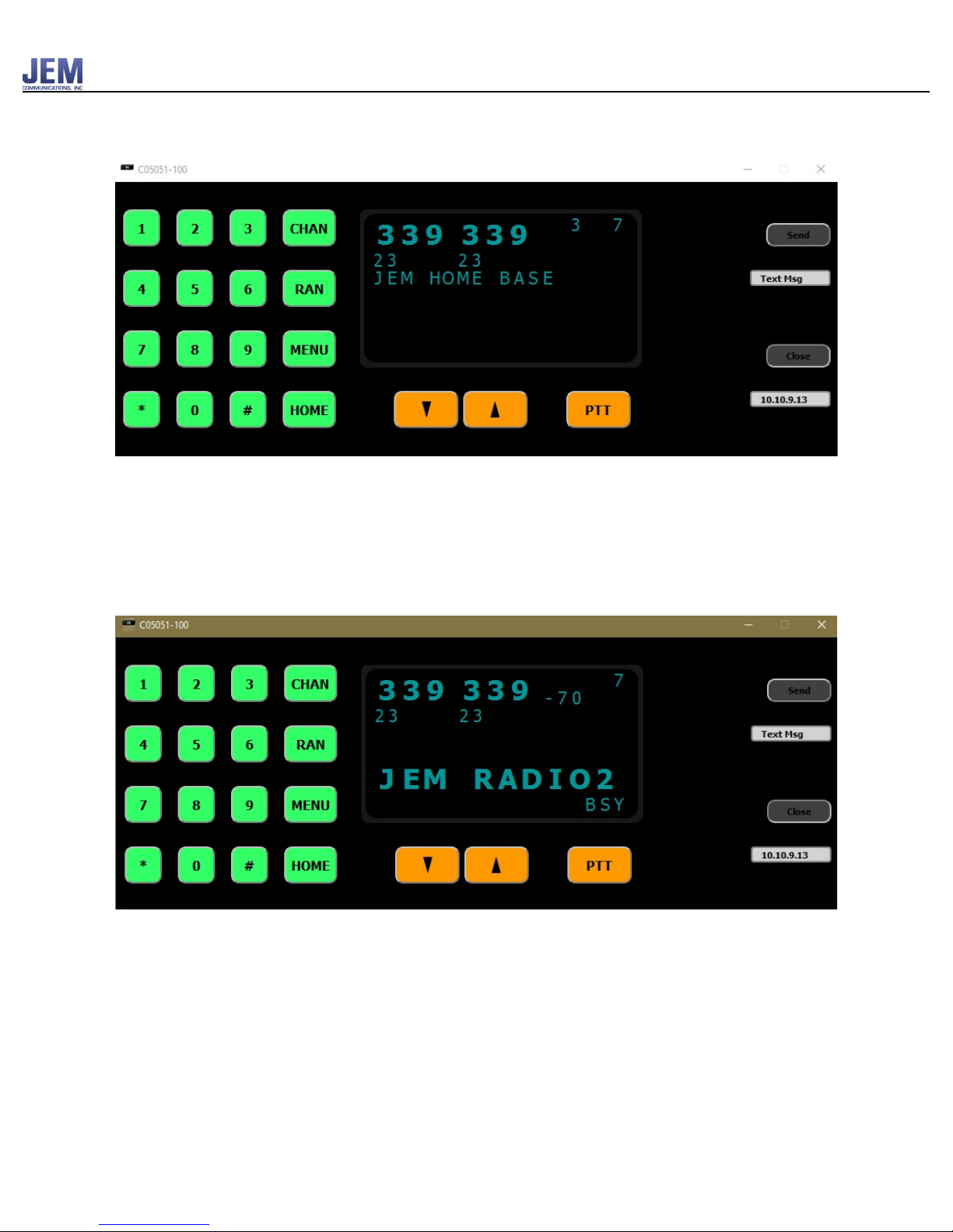
Display
The normal display will show the 6 digit AAR channel number in enlarged print. The home
channel number and channel label (if there is one) along with the volume. The home channel
label is displayed on the 4th line. This is also where digital messages are displayed as well as
RAN code and HOME channel entry prompts.
When a reception is received from another radio, the RSSI value will be shown and “BSY” will
be displayed in the lower right corner.
When a reception is received from another radio on a digital channel and the RAN codes match,
the display will toggle between the unit ID and talk group of the transmitting radio. If the RAN
codes do not match, “BSY” will be displayed but the display will not show the unit ID or talk
group.
When the radio is transmitting, “TX” will be displayed in the lower right corner. The volume is
displayed in the upper right corner. The home channel number is displayed on the top line just to
the left of the volume number.
3

JEM Radio II
Operation Guide
Channel Entry
A channel entry consists of entering 6 digits. The first 3 are the AAR TX channel and the second
three are the AAR RX channel. The default RAN of 01 (Freq, 67.0Hz) will automatically be used
on digital channels when the channel is changed. If a different RAN code is required, it can be
entered using the RAN button where the first 2 digits is the TX ran code and the second is the
RX ran code.
Shortcuts
If only 3 digits are entered, it will be assumed that the RX channel should be the same as the TX
channel and the new channel will automatically be selected after the timeout period or the
CHAN button is hit.
If a non default RAN code is required, the RAN button can be hit immediately after the 3rd digit
instead of the CHAN button. This will confirm the channel entry just like hitting the CHAN
button but will also automatically prompt for the new RAN codes.
Text Messages
A text message that is received either from an NXDN packet or from the network will be scrolled
across the display once, after which MSG will blink in bottom right corner of display.
If a text message is received before a previous message is finished scrolling, the new message
will begin scrolling immediately and the previous message will be saved. Messages will be saved
in non-volatile memory.
There is an option in the GENERAL menu to replay any of the last 10 text messages received.
The SCROLL MSG option number is set to ‘1’ by default which is the last message received.
Simply selecting the SCROLL MSG option and then hitting the MENU button will play the last
message. Changing the message number allows selecting older messages with ‘10’ being the
oldest. Selecting ‘0’ will play all 10 messages.
Any message received by the radio when in menu mode will be stored and displayed once menu
mode is exited.
After a message is received, the text “MSG” will be displayed every second until the user
acknowledges it by hitting any button.
4

JEM Radio II
Operation Guide
Buttons
• The number buttons 0 – 9, ‘*’, ‘#’ are used to send DTMF tones, enter AAR channels, enter
RAN codes and make menu selections.
• The PTT (Push To Talk) button will put the radio in transmit mode.
• The VOLUME button will increment/decrement the audio volume of the front panel speaker as
well as the speaker outputs on the 12 pin connector on the back of the radio.
• The CHAN button allows for AAR channel number entries.
• The MENU button accesses extra options such as read text messages and change some radio
settings.
• The RAN button allows for the entry of RAN codes when on a digital channel or PLL tones
when on an analog channel. See (Appendix A). Pressing RAN when on a digital channel
button will display “RAN _ _ _ _”.
• Pressing RAN when on an analog channel will display “PLL _ _ __” (Feature needs to be
enabled, refer to JEM Radio II Software Guide.)
• Pressing Home followed by #will revert to the previous Channel/RAN/PLL that the radio was
on."
5
JEM Radio II
Operation Guide
Headset Use
The radio has been designed so that headsets can be used directly with the radio without the use
of external boxes that contain amplifiers/mixers and volume controls.
The radio has independent volume control of the "fixed" level audio outputs on the 6 and 12 pin
connectors on the deck and 6 pin connector on the head when it's installed separate from the
deck. These outputs can drive headset speakers directly (8 ohms) without the requirement for an!
external amplifier. Any microphone input (other than the panel mic) can be mixed into any audio
output so the user can control how much of his own voice (side tone) he hears relative to the
other audio sources which could be another user, audio from the radio or audio from the IP
network.
IP Network Use
The network interface allows the following functions, firmware updates, text messages to the
display, getting unit ID from the locomotive network and sending/receiving audio data. !
Virtual Control Head
A command can be sent to the radio that will cause it to send all the data that gets sent to the
display to also get sent out the PC port serial port or the Ethernet port. This makes it possible to
write a software application that can display the data as well as send button press commands to
the radio essentially making it a software equivalent of the control head.
6

JEM Radio II
Operation Guide
Secondary Control Head
A second control head can be connected to the 12 pin connector and used on the conductor side
of the locomotive.
7
JEM Radio II
Operation Guide
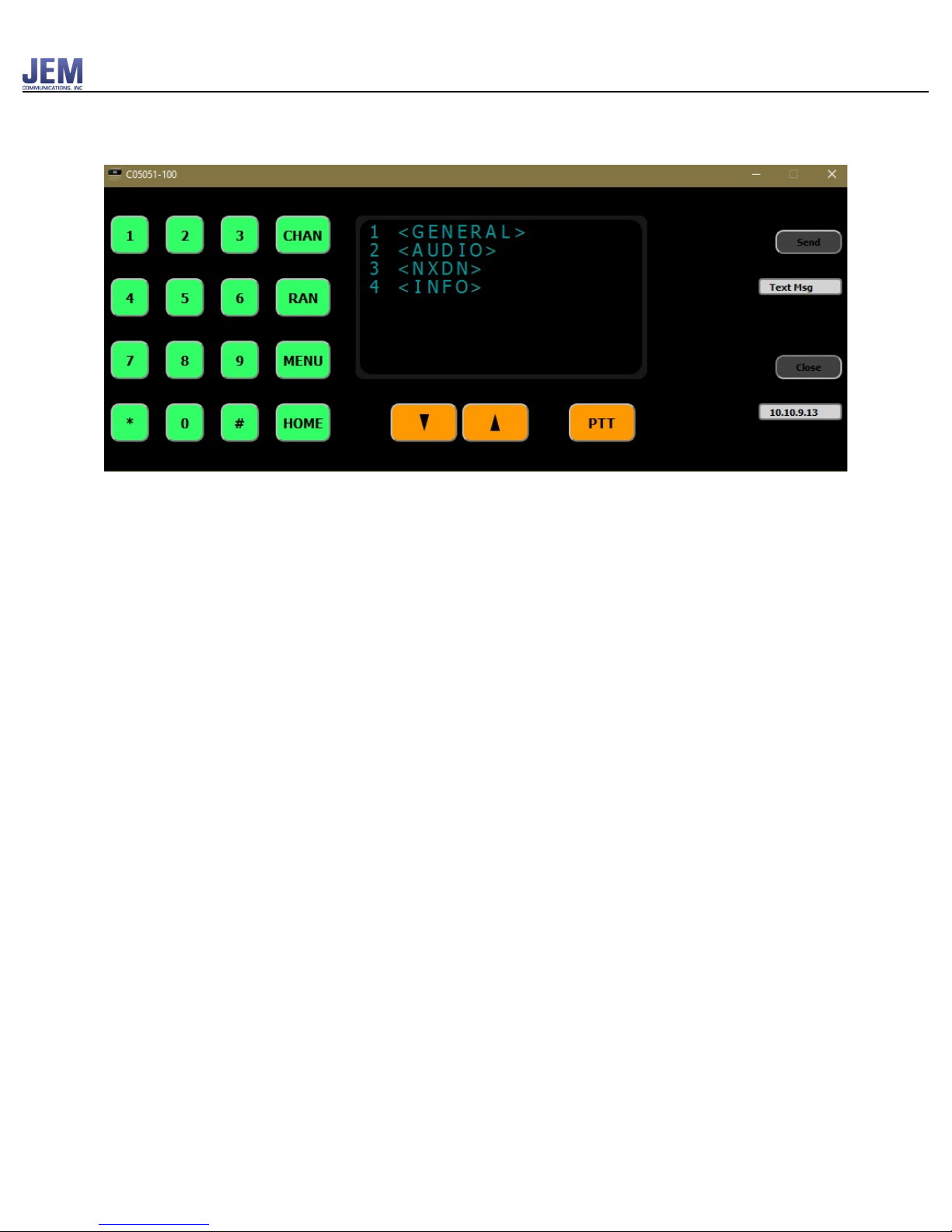
Menus
The menu key will bring up a list of options that can be selected with the number keys.
Once the option is selected, the value can be incremented or decremented by using the volume
control button. When menus are displayed, hitting the menu key again will exit the menu mode.
Hitting the CHAN, HOME, or PTT button will also exit menu mode. See (Appendix E) for the
menu hierarchy.
Note, some of these features can be disabled during programming if the customer does not want
users altering audio or NXDN settings. Please refer to the JEM Radio II Software Guide for more
information. "
8

JEM Radio II
Operation Guide
GENERAL
GENERAL
DESCRIPTON
1 BRIGHTNESS
Values (1 – 4) that control how bright the
display is
2 VOL OFFSET
Controls the relative volume of the speaker
outputs on pins M&N of the 12 pin connector
to the level of the panel speaker. A positive
value will make the volume louder than the
panel speaker. Value can range from (-10 to +
10).
3 SCRLL MSG
Set number to select any 0 -10 of the last
messages received where 1 selects the most
current message. Simply selecting the SCRLL
MSG line will trigger message 1 to scroll. A
value of 0 will cause all message to be
scrolled.
4 <SET DEFAULTS>
Sets all of the audio levels back to the default
states.
See (Appendix B)
9

JEM Radio II
Operation Guide
AUDIO
AUDIO
DESCRIPTON
1 <USER 1>
The connection to the 6 pin connector
2 <USER 2>
The connection to the 12 pin connector
3 <USER 3>
The connection to the 6 pin connector on the
back of the head when it is mounted
separately from the deck.
4 <FACTORY>
<USER 1> or <USER 2> or <USER 3>
MASTER
The main volume of this output
MY LEVEL
The level that is heard on the audio out pin
from the mic input of the same connector.
(Sidetone)
OTHER
The level that is heard on the audio out from
the mic inputs of the other 2 connectors.
<FACTORY>
From Radio
Level of audio coming from Radio when it’s
in RX mode
To Radio
Level going to the input of the internal radio.
(This will affect the deviation of the radio)
Panel Mic
Control sensitivity of the panel Mic. A value
of 20 is unity gain through the volume. A
higher value will make it more sensitive.
10

JEM Radio II
Operation Guide
NXDN
INFO
Error Messages
DIGIAL
DESCRIPTON
1 DEFLT RAN
RAN codes should be entered for each home
channel in the C05053 program on digital
channels. If no values are entered, it will by
default write RAN codes of 00 00 and a
parameter error will be displayed as a warning
when the data is written to the device.
INFO
DESCRIPTON
“Serial Number”
DECK VER
JEM supplied firmware for the deck of the
radio
HEAD 1 VER
JEM supplied firmware for the head of the
radio
HEAD 2 VER
JEM supplied firmware for the 2nd head of
the radio if there is one.
MODEL
Model of internal radio
RADIO FIRM
ICOM/KWND supplied firmware
Message
Cause
“NON-HOME ONLY”
RAN button is hit when on a home channel
“PTT is ON”
When the radio powers up and any of the PTT inputs are
low (active), the radio will print out the message “PTT is
ON” to alert the user that there may be a stuck PTT source.
The radio will not go into transmit mode until all of the PTT
inputs are first inactive.
11

JEM Radio II
Operation Guide
Cable Connectors
Remote Control Head Connector (19-Pin)
PIN
Signal
A
Audio Out
E
GND
F
Hook 1
J
VCC
K
VCC
L
Mic Audio 3
M
Speaker -
N
Speaker +
S
RXF 232
T
TXF 232
U
PTT 1
V
Mic Panel
12
JEM Radio II
Operation Guide
Power Connector (4-Pin)
!
Rear Handset Connector (6-Pin)
PIN
Signal
Description
A*
+ 74 Vdc
Primary isolated input voltage
B
- 13.6 Vdc
Radio common (chassis)
C*
- 74 Vdc
Primary isolated input voltage
D
+ 13.6 Vdc
Regulated radio voltage input
*Only one supply voltage can be
used at a time.
PIN
Signal
Description
A
Mic Audio
Modulation input from handset
microphone
B
Mic Ground
Mic Audio return (common
with radio chassis)
C
PTT
Push-To-Talk input
D
PTT Ground
PTT return path (common with
radio chassis)
E
Receive Audio
Audio input to receiver
element in handset
F
Hook Switch
Optional input connected to
the handset cradle switch
13

JEM Radio II
Operation Guide
Accessories Connector (12-Pin)
PIN
Signal
Description
A
Remote Mic
Remote microphone audio
input
B
Mic Ground
Remote microphone ground
C
Remote PTT
Input signal for remote
transmit activation
D
PTT Return
PTT reference (common)
E
Remote Audio
Low level audio output
F
+ 13.6 Vdc
Low power (1Amp max)
H
Audio Return
Remote audio common
J
13.6 Vdc Return
13.6 Vdc common (chassis)
K
#
Do Not Use
L
#
Do Not Use
M
External Speaker
Remote speaker
N
External Speaker
Remote speaker return
14

JEM Radio II
Operation Guide
(Appendix A)
PLL Frequency lookup table
When on an analog channel, PLL frequencies could be entered using the RAN button with the
following conversion table.
2 Digit Code
Frequency (Hz)
2 Digit Code
Frequency (Hz)
00
NO TONE
28
167.9
01
67.0
29
173.8
02
69.3
30
179.9
03
71.9
31
186.2
04
74.4
32
192.8
05
77.0
33
203.5
06
79.7
34
210.7
07
82.5
35
218.1
08
85.4
36
225.7
09
88.5
37
233.6
10
91.5
38
241.8
11
94.8
39
250.3
12
97.4
13
100.0
14
103.5
15
107.2
16
110.9
17
114.8
18
118.8
19
123.0
20
127.3
21
131.8
22
136.5
23
141.3
24
146.2
25
151.4
26
156.7
27
162.2
15

JEM Radio II
Operation Guide
(Appendix B)
Default Values
Setting
Value
Volume Offset
0
Audio Out 1
16
Audio Out 2
16
Audio Out 3
16
Mic 1
0
Mic 2
0
Mic 3
0
Mic 2/3
0
Mic 1/3
0
Mic 1/2
0
16

JEM Radio II
Operation Guide
(Appendix E)
!
1 <GENERAL>
2 <AUDIO >
3 <NXDN>
4 <INFO>
MAIN
1 BRIGHTNESS
2 VOL OFFSET
3 SCRLL MSG
4 <SET DFLTS>
5 <BACK>
GENERAL
SN
DECK VER
HEAD VER
HEAD2 VER
MODEL
RADIO FIRM
7 <BACK>
INFO
1 DFLT RANTX
2 DFLT RANRX
3 <BACK>
DIGITAL
1 <USER 1>
2 <USER 2>
3 <USER 3>
4 <FACTORY>
5 <BACK>
AUDIO
1 MASTER
2 MY LVL
3 OTHER
4 <BACK>
USER 1-3
CONFIRM?
2 YES
3 <BACK>
SET DFLTS
1 FROM RADIO
2 TO RADIO
3 PANEL MIC
4 <BACK>
FACTORY
17
Table of contents


