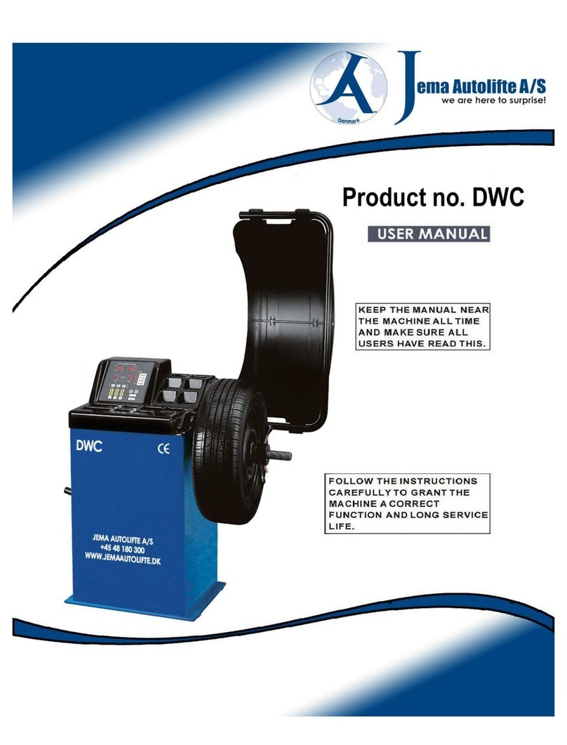
Jema Autolifte DWB-8-E User manual

Jema Autolifte A/S Industrihegnet 2 4030 Tune Denmark Tel. (+45) 48180300 [email protected] www.jemaautolifte.dk
Tyre changer
DWB-8-E
Euro line
OPERATING MANUAL

Jema Autolifte A/S Industrihegnet 2 4030 Tune Denmark Tel. (+45) 48180300 [email protected] www.jemaautolifte.dk
TABLE OF CONTENTS
1. General
page
3
2. Installation
page
3
3. Description
page
5
4. Demounting tyre
page
8
5. Mounting tyre
page
10
6. Operating considerations
page 11

Jema Autolifte A/S Industrihegnet 2 4030 Tune Denmark Tel. (+45) 48180300 [email protected] www.jemaautolifte.dk
1 GENERAL
Tyre changer / removal machine DWB-8-E is designed for fitting / removal of tube and tubeless tyres
on wheels of cars and vans. It may also be used for light - alloy wheels as its working parts do not
distort the delicate structure of such wheels.
DWB-8-E is capable of performing the following functions:
Basic version:
- separation of tyre from wheel rim
- tyre removal and fitting
- inflation by means of an air - gun with pressure gauge
Extended version - additionally:
- surge inflation of tubeless tyres
1. Set up machine on a hard, flat base
2. Connect supply cable to 3x380V/50Hz socket.
NOTE:
The machine is provided with a four - core supply cable. Green - yellow wire, connected to
machine housing is a protective wire. Other three wires are phase wires.
TECHNICAL DATA:
- tyre diameter range
- max tyre width
- wheel clamping on machine
- column deflection
- supply air working
- power supply
- power input
- motor rating
- separator pressure on tyre
- required floor space
- machine height
- machine weight
to 23 inches
12 inches
pneumatic
pneumatic
from 0,8 to 1,0 MPa
3 x 380V / 50Hz (+10%, -15%)
0,8 kVA
0,75 kW
1,5 tonnes (at 1 MPa)
800 x 900 mm
1450 mm
ok. 200 kg
2. INSTALLATION
3

Jema Autolifte A/S Industrihegnet 2 4030 Tune Denmark Tel. (+45) 48180300 [email protected] www.jemaautolifte.dk
NOTE:
The plug is not included in machine equipment. The user should procure a plug, suitable to the mains
socket, installed in his workshop.
After connecting to the power supply, check the sense of rotation of the motor: after depressing table
rotation pedal (item 19 fig 4) the worktable should rotate clockwise. If the table rotates anticlockwise
interchange two phase wires in the plug.
3. Connect compressed air hose to supply coupling (item 1 fig 1). Use pneumatic hose min. 1
MPa working pressure, 8 mm inside diameter. Check whether oiler 5 is filled with oil.
NOTE:
Top - up compressed air lubricator with oil periodically (item 5 fig 1 ). In lubricator lid two screws can
be seen; the smaller one is used for adjusting lubrication rate the larger one closes oil filler, through
which oil may be injected with a syringe. The transparent reservoir may also be c a r e f u l l y
unscrewed from the lubricator body and filled directly with oil. Use mineral oils, free of water and
acids, 2 to 4 Angler viscosity (at 50 degrees cent.). HL 32 hydraulic oil is recommended. Air filter -
water separator is maintenance - free - it is self - cleaning.
Fig. 1. Connections
1- supply coupling, 2- inflating coupling, 3- extra air outlet (to be used by the customer),
4- compressed air lubricator,5- extra electric protective terminal
4

Jema Autolifte A/S Industrihegnet 2 4030 Tune Denmark Tel. (+45) 48180300 [email protected] www.jemaautolifte.dk
3. DESCRIPTION
Tyre changer DWB-8-E is provided with an electro pneumatic drive. Separation of tyre from wheel rim,
column deflection, clamping the wheel on the worktable, locking the slide and arm with foot in working
position is performed by means of pneumatic actuators. The worktable is rotated by means of an
electric motor. Major machine units are shown in figs. 2, 3,4, and 5.
Fig 2 Major machine units
7-worktable, 8-table jaws, 9-column, 10-slide, 11-arm,
12-tyre separator, 13-tyre inflation gun,
Fig. 3 View of the back wail
6- Extra protective terminal,
15- supply table
5

Jema Autolifte A/S Industrihegnet 2 4030 Tune Denmark Tel. (+45) 48180300 [email protected] www.jemaautolifte.dk
16 17 18 19 Fig 4 Control pedals
Wheel clamping pedals (item.16)
Controls onward and inward movement of jaws of the worktable. It has three working positions:
1 - top position - jaws closed (shifted towards table centre )
2- mid position - shifting jaws outwards, to any distance.
How to operate pedal in mid position:
- press pedal gently until a click is heard
- remove your foot to lock pedal in mid position
Subsequent precision of pedal will stop jaw movements. Press pedal gently to avoid its shifting
to bottom position.
3- bottom position - full outward travel of jaws. Subsequent precision of pedal shifts it into top position.
Column deflection pedal (item.17)
Have three working positions:
1 - top position - column in working position (vertical)
2- mid position - backward deflection of column to any distance.
how to operate the pedal in mid position:
- press pedal gently until click is heard
- remove your foot to lock pedal in mid position
- subsequent precision of pedal will result in deflection of column and release of the pedal will
stop the movement. Press pedal gently to avoid its shifting to bottom position.
6

Jema Autolifte A/S Industrihegnet 2 4030 Tune Denmark Tel. (+45) 48180300 [email protected] www.jemaautolifte.dk
3- bottom position - max backward deflection of column. Subsequent depression of pedal shifts it to
top position 9 moves column to the vertical).
Tyre separator pedal (item.18)
Have two working positions:
1- top position (initial position ) - separator disengaged
2- depressing the pedal engages the separators, release of pedal disengages separator.
Worktable rotation pedal (item.19)
Has three working position:
1- mid position ( initial ) - table drive disengaged
2- pressing the pedal engages clockwise rotation of table (operating rotation), release of pedal
disengages rotation.
3- lifting the pedal with your foot from mid position engages anticlockwise rotation of table 9 emergency
rotation) release of pedal disengages rotation
Slide locking knob (item.20)
Turning the knob from its initial position to the left locks the slide and arm with foot in operating
position. Turning the knob to the left unlocks the slide and throws the arm with foot upwards.
Fig. 5. View of working head
7

Jema Autolifte A/S Industrihegnet 2 4030 Tune Denmark Tel. (+45) 48180300 [email protected] www.jemaautolifte.dk
4. DEMOUNTING TYRE
Switch machine and air supply on.
Pull tyre separator lever 21 back, insert wheel between separator arm and rubber cushion on machine
wall and move the arm to touch the tyre, close to wheel rim edge.
BE CAREFUL NOT TO REST THE ARM AGAINST WHEEL RIM
Holding separator arm in appropriate position, depress tyre separator pedal 18 and hold it until the
tyre is separated from wheel edge. If necessary, repeat the operation at several points of wheel
circumference. Then reverse wheel and separate in the same way tyre from wheel rim on the other
side of the wheel.
Fig 6. Separating the tyre
21 - tyre separator lever
By means pedal 17, deflect column backwards. With pedal 16 open table jaws (pedal in mid and
bottom positions). Set - up wheel on work table so that the tyre rests against jaws and shift pedal 16
to top position. Check if jaw hitches gripped wheel rim edge securely. Shift pedal 17 to top position
-the column will revert to the vertical working position). Grip, with your left hand, the top of lever 11
and with your right hand, the slide locking knob 20. Sliding the slide out, to an appropriate distance
and pressing the arm top, make the foot rest on the wheel rim edge, as in fig 9. Then turn knob 20 to
the right arm and slide will be loaded and the foot will automatically adopt the working position,
taking into account the necessary clearance between the foot and the wheel rim. Press tyre edge,
opposite to the foot into wheel rim recess. Rest tyre lever against the support of foot 22 and pull tyre
edge on bulb 23 - as in gigs 10 and 11.
8
Beadbreaker
function
Beadbreaker
function

Jema Autolifte A/S Industrihegnet 2 4030 Tune Denmark Tel. (+45) 48180300 [email protected] www.jemaautolifte.dk
Fig. 7. Foot parts: 22-support, 23-bulb, 24-shoe
Fig. 9. Foot in operating position
Fig. 8 Setting working head
Fig. 10 pulling tyre edge onto shoe
9

Jema Autolifte A/S Industrihegnet 2 4030 Tune Denmark Tel. (+45) 48180300 [email protected] www.jemaautolifte.dk
Bottom tyre edge is removed from the wheel rim without changing wheel clamping or foot position.
Remove only the tube, push tyre edge opposite the foot into wheel rim recess from underneath
and repeat tyre removal operation, as described above.
Unlock arm and slide with knob 20.
Deflect column backwards with pedal 17.
Open worktable jaws with pedal 16 and remove wheel rim from machine.
Deflect column backwards with pedal 17. With pedal 16 open table jaws (pedaling mid or bottom
position). Set - up wheel on worktable and shift pedal 16 to top position. Check whether jaw hitches
gripped wheel rim edge securely. Shift pedal 17 to top position - the column will return to vertical
(operating position).
Grip with your left hand the top of lever 11 and with your right hand - the slide locking knob 20. By
moving slide outwards to an appropriate distance and pressing the top of the arm, bring the foot to
rest against wheel rim edge, as shown in fig 9. Then turn knob 20 to the right - the arm and slide will
lock and the foot will automatically adopt operating position, taking into account the necessary
clearance between foot and wheel rim.
Place tyre on wheel rim.
Push bottom tyre edge, opposite the foot into wheel rim recess. Put opposite tyre edge on foot slide
24 and push under roller 23 - as shown in fig. 12.
5. MOUNTING TYRE
Fig.12. Mounting Tyre
10

Jema Autolifte A/S Industrihegnet 2 4030 Tune Denmark Tel. (+45) 48180300 [email protected] www.jemaautolifte.dk
Depressing pedal 19, rotate worktable clockwise until bottom tyre edge is placed on the wheel rim.
Should problems occur during fitting the tyre, e.g. jamming, release pedal and then lift it with your
foot.
Install tube.
Push top tyre edge opposite the foot into wheel rim recess and install top tyre edge on wheel rim,
proceeding in the same way as for the bottom edge.
Inflate tyre means of air gun with pressure gauge or by means of automatic inflator (description how
to operate the inflator will be found in the latter part of these instructions).
Unload arm and slide with knob 20.
Deflect column backwards with pedal 17
Open worktable jaws with pedal 16 and remove wheel from machine.
6. OPERATING CONSIDERATIONS
The worktable is driven by an electric motor through a worm gear, lubricated with Shell OMALAA
oil 680. After 4000 h operation (excluding breaks), clean the gear and change oil.
11
8. WARRANTY
Jema Autolifte provide 1 year warranty - All repairs and adjustments are to be made by the Jema Autolifte
Machine repairs during warranty period by users own means will result in cancellation of warranty.

Jema Autolifte A/S Industrihegnet 2 4030 Tune Denmark Tel. (+45) 48180300 [email protected] www.jemaautolifte.dk
Jema Autolifte
XXX-XXXX Co. Ltd.
MANUFACTURING PLANT & STORE
xx. xxxxxxx 11,11 - 111 Warsaw
POLAND
*****************************************************************************************************************************************
WHEEL BALANCING MACHINES TYRE CHANGERS EQUIPMENTS FOR TYRESHOPS
*****************************************************************************************************************************************
Statistic number : 001111111 Tax number : 111 - 111 - 11 - 11
*****************************************************************************************************************************************
CE Conformity Declaration
in accordance with directives : 98/37/CE and 89/336/CEE
We : XXX-xxxx Co. Ltd.
XX. XXXXXXX 11
01-932 Warsaw
Poland
declare, under our exclusive responsibility, that the product
Tyre changer type DWB-8-E
version standard
to which this declaration refers, is in conformity with the following provisions of law:
- directive 98/37/CE ( the safety of machinery );
- directive 89/336/CEE and following modifications ( the electromagnetic compatibility).
For verification of conformity with the provisions of law were consulted the harmonized standards or other norms
documents:
Basic concepts, general principles for design - Part 1;
Basic concepts, general principles for design - Part 2;
Generic emission standard, residential, commercial and light industry;
Generic emission standard, industrial environment;
Generic immunity standard, residential, commercial and light industry;
Generic immunity standard, industrial environment;
Safety distances to prevent danger zones being reached by the upper limbs;
Minimum gaps to avoid crushing of parts of the human body;
Marking electrical equipments with ratings to electrical supply - Safety
requirements.
Electrical accessories;
Safety of machinery - Safety requirements for fluid power systems and their
components - Pneumatics
- PN - EN 292 -1 / 2000
- PN - EN 292 - 2 / 2000
-PN-EN 50081 -1 /1996
-PN - EN 50081 - 2/1996
-PN-EN 50082 -1 /1999
-PN-EN 50082 -2/1997
-PN-EN 294/1994
-PN-EN 349/1999
-PN-EN 61293/2000
- 62 / 2002
-PN-EN 983/1999
This declaration is valid for all products which are produced in accordance with the technical documentation which
part of this declaration.
Warsaw, 01.05.2004
Signature

Jema Autolifte A/S Industrihegnet 2 4030 Tune Denmark Tel. (+45) 48180300 [email protected] www.jemaautolifte.dk
Jema Autolifte
xxx - xxxx Co. Ltd.
MANUFACTURING PLANT & STORE
xx. xxxxxxx 11,11 - 111 Warsaw
POLAND
******************************************************************* ■к**********************************************************************
WHEEL BALANCING MACHINES TYRE CHANGERS EQUIPMENTS FOR TYRESHOPS
******************************************************************************************************************************************
Statistic number : 001111111 Tax number : 111 - 111 - 11 - 11
******************************************************************************************************************************************
CE Conformity Declaration
in accordance with directives: 98/37/CE and 89/336/CEE
We : XXX-xxxx Co. Ltd.
XX. XXXXXXX 11
01-932 Warsaw
Poland
declare, under our exclusive responsibility, that the product
Tyre changer type DWB-8-E
version standard
to which this declaration refers, is in conformity with the following provisions of law :
- directive 98/37/CE ( the safety of machinery );
- directive 89/336/CEE and following modifications ( the electromagnetic compatibility).
For verification of conformity with the provisions of law were consulted the harmonized standards or other norms
documents :
Basic concepts, general principles for design - Part 1;
Basic concepts, general principles for design - Part 2;
Generic emission standard, residential, commercial and light industry;
Generic emission standard, industrial environment;
Generic immunity standard, residential, commercial and light industry;
Generic immunity standard, industrial environment;
Safety distances to prevent danger zones being reached by the upper limbs;
Minimum gaps to avoid crushing of parts of the human body;
Marking electrical equipments with ratings to electrical supply - Safety
requirements.
Electrical accessories;
Safety of machinery - Safety requirements for fluid power systems and their
components - Pneumatics
- PN - EN 292 -1 / 2000
- PN - EN 292 - 21 2000
-PN-EN 50081 -1 /1996
-PN-EN 50081 - 2/1996
-PN-EN 50082 -1 /1999
-PN-EN 50082-2/1997
-PN-EN 294/1994
-PN-EN 349/1999
-PN-EN 61293/2000
- 62 / 2002
-PN-EN 983/1999
This declaration is valid for all products which are produced in accordance with the technical documentation which
part of this declaration.
Warsaw, 01.05.2004
Wiesław Roguski
Chairman of Board
Signature

Jema Autolifte A/S Industrihegnet 2 4030 Tune Denmark Tel. (+45) 48180300 [email protected] www.jemaautolifte.dk
Industrihegnet 2
4030 Tune
Denmark
Tlf. (+45) 48180300
E-mail: [email protected]
Website: http://www.jemaautolifte.dk
Table of contents
Other Jema Autolifte Tyre Changer manuals
Popular Tyre Changer manuals by other brands

Hofmann
Hofmann monty 3550 Operation instructions, Spare parts list

Corghi
Corghi A 222 Operator's manual

Hunter
Hunter TCA34R Series Operation instructions

John Bean
John Bean QUADRIGA 1000 Operator's manual

WERTHER INTERNATIONAL
WERTHER INTERNATIONAL TITANIUM2000 Manual for the user

Cormach
Cormach FT 26S Use and maintenance manual

Ranger Products
Ranger Products R980AT Installation and operation manual

Hoffman
Hoffman monty 8600 Series Operation manual

Ranger Products
Ranger Products RX3040 Installation and operation manual

Zipper Mowers
Zipper Mowers ZI-RMM94H-230V Operation manual

Corghi
Corghi A 2024 LL Operator's manual

PELA
PELA 498192 manual