Jenaer Antriebstechnik EtherCAT CANopen ECOVARIO 616 User manual
Installation and Operating Instructions
ECOVARIO® 616
ECOVARIO® 616 D


Subject to change without notice!
Installation and Operating Instructions ECOVARIO® 616, 616 D
3
Edition Comment
April 2013 Preliminary version for prototypes
July 2013 Preliminary version for UL certification
Nov 2013 French translation of safety instructions added because of UL requirements
June 2015 Series; added: Profinet interface, RFI suppression filter
Published editions:
All rights reserved:
Jenaer Antriebstechnik GmbH
Buchaer Straße 1
07745 Jena
No parts of this original instructions may be translated, reprinted or reproducted on microlm or in other
ways without written permission by Jenaer Antriebstechnik GmbH.
e content of this document has been worked out and checked carefully. Nevertheless dierences from the
real state of the hard and soware can never be fully excluded. Necessary corrections will be carried out in
the next edition.
ECOSTEP®, ECOVARIO® und ECOLIN® are registered trademarks of Jenaer Antriebstechnik GmbH, Jena.
BISS® is a registered trademark of iC-Haus GmbH, Bodenheim.
CANopen® is a registered community trademark of CAN in Automation e.V., Nuremberg.
EnDat® is a registered trademark of Dr. Johannes Heidenhain GmbH, Traunreut
EtherCAT® is a registered trademark and patented technology, licensed by Beckho Automation GmbH,
Germany.
HIPERFACE® is a registered trademark of SICK STEGMANN GmbH, Donaueschingen.
Windows® is a registered trademark of Microso Corporation in the United States and other countries.

Installation and Operating Instructions ECOVARIO® 616, 616 D
4Subject to change without notice!

Subject to change without notice!
Installation and Operating Instructions ECOVARIO® 616, 616 D
5
Inhalt
1 About this manual ......................................................................................................................... 7
2 Safety instructions ......................................................................................................................... 7
2.1 Signal words and Symbols used .................................................................................................................7
2.2 General notes................................................................................................................................................8
2.3 Dangerous voltages ......................................................................................................................................8
2.4 Danger by hot surfaces ................................................................................................................................ 8
2.5 Danger by unintentional mechanical movements...................................................................................9
2.6 Prescribed use............................................................................................................................................... 9
3 Legal notes.................................................................................................................................... 10
3.1 Terms of delivery..........................................................................................................................................10
3.2 Liability..........................................................................................................................................................10
3.3 Standards and directives..............................................................................................................................10
3.3.1 UL/CSA conformity according to UL 508C (under preparation).........................................................10
3.3.2 CE conformity ..............................................................................................................................................11
4 Technical Data.............................................................................................................................. 13
4.1 Equipment.....................................................................................................................................................13
4.2 Rated data of the power stage..................................................................................................................... 14
4.3 General technical data................................................................................................................................. 15
4.4 Order key.......................................................................................................................................................16
4.5 Suitable types of motors .............................................................................................................................. 17
4.5.1 ECOSPEED motors .....................................................................................................................................17
4.5.2 Direct linear motors ECOLIN® ..................................................................................................................17
4.5.3 DC servo motors..........................................................................................................................................17
5 Installation................................................................................................................................... 18
5.1 Mounting.......................................................................................................................................................18
5.1.1 Inportant notes............................................................................................................................................. 18
5.1.2 Dimensions ...................................................................................................................................................18
5.1.3 Assembly .......................................................................................................................................................19
5.2 Electrical Installation...................................................................................................................................20
5.2.1 Important notes............................................................................................................................................ 20
5.2.2 EMC compliant installation........................................................................................................................ 20
5.2.3 Connection diagram.................................................................................................................................... 21
5.2.4 Types of lines ................................................................................................................................................ 23
5.2.5 Operation with residual current devices...................................................................................................23
6 Interfaces...................................................................................................................................... 24
6.1 Overview .......................................................................................................................................................24
6.2 Control signals.............................................................................................................................................. 26
6.2.1 X1A, X1B: Digital inputs and outputs, 24 V............................................................................................. 26
6.2.2 X2A, X2B: Digital Inputs ............................................................................................................................27
6.3 Power interfaces ...........................................................................................................................................28
6.3.1 X4: Ballast resistor........................................................................................................................................28
6.3.2 X5A/X5B: Motor connection .....................................................................................................................30
6.3.3 X6 Power Connection..................................................................................................................................31
6.3.4 X7A, X7B: Brake...........................................................................................................................................32
6.4 Safety functions ............................................................................................................................................33

Installation and Operating Instructions ECOVARIO® 616, 616 D
6Subject to change without notice!
6.4.1 Restart lock / Safe torque o (STO)........................................................................................................... 33
6.5 Encoders........................................................................................................................................................36
6.5.1 2-Axis Servo Ampliers ECOVARIO 616 D: X11, X12: Encoder ......................................................... 37
6.5.2 1-Axis Servo Amplier ECOVARIO 616: X11, X12: Encoder............................................................... 39
6.6 Serial interfaces ............................................................................................................................................41
6.6.1 X13: RS485/RS232 interface with 2 Capture Inputs................................................................................41
6.6.2 X14: Parameterizing USB interface ...........................................................................................................44
6.7 X21: CAN interface......................................................................................................................................45
6.8 Optional interfaces.......................................................................................................................................46
6.8.1 X22: Designs with encoder emulation ......................................................................................................46
6.8.2 X22: Designs with PROFIBUS DP-V0 interface......................................................................................47
6.8.3 X22: Designs with Ethernet interface........................................................................................................49
6.8.4 X22: Designs with EtherCAT® interface....................................................................................................52
6.8.5 X22: Designs with Pronet interface.........................................................................................................55
7 Commissioning............................................................................................................................ 58
7.1 Important notes before commissioning.................................................................................................... 58
7.2 Control and display elements.....................................................................................................................58
7.3 Work schedule commissioning ..................................................................................................................59
7.3.1 State display...................................................................................................................................................60
7.3.2 Error messages.............................................................................................................................................. 61
7.3.3 Setting and querying displaying parameters via the keys....................................................................... 64
7.3.4 Bootloader mode..........................................................................................................................................64
8 Parameter setting......................................................................................................................... 65
8.1 User interface ECO Studio..........................................................................................................................65
8.2 Setting the current allocation to the both axes of the ECOVARIO 616 D ...........................................65
9 Accessories ................................................................................................................................... 66
9.1 Supplementary parts.................................................................................................................................... 67
9.1.1 Shield set........................................................................................................................................................67
9.2 Ballast resistors .............................................................................................................................................68
9.2.1 Ballast resistors 200 W (500 W cooled) .................................................................................................... 69
9.3 Mating connector sets .................................................................................................................................70
9.4 Cables............................................................................................................................................................. 71
10 Appendix...................................................................................................................................... 72
10.1 Glossary......................................................................................................................................................... 72
10.2 Index of formulae......................................................................................................................................... 74
10.3 Index of standards and directives ..............................................................................................................74
Subject to change without notice!
Installation and Operating Instructions ECOVARIO® 616, 616 D
7
1 About this manual
is original instructions describe the servo amplier range ECOVARIO® 6xx. It concerns to all persons
who project, install and commission ECOVARIO® 616 or ECOVARIO® 616 D drives.
Further information:
Soware commissioning: „ECO Studio Operation Manual ECOVARIO®, ECOSTEP®, ECOMPACT®“
Programming: manual „Object Dictionary ECOVARIO® and ECOSTEP®“, soware tool ECO Studio
Application Notes ECOVARIO® and ECOSTEP®
Motor data: Product catalogue „ECOSTEP®/ECOVARIO®/ECOLIN® Drives“.
is manual makes the following demands on qualied personnel:
Transport: Personnel trained in handling electrostatic sensitive devices
Installation: Electrotechnically qualied personnel who know the security directives of electrical enginee-
ring and automation
Setup/Commissioning: Qualied personnel with a broad knowlege of the elds of electrical engineering,
automation and drives.
Knowledge of machine safety legislation is compulsory.
2 Safety instructions / Consignes de sécurité
2.1 Signal words and symbols / Mots d‘avertissement et symboles
Table 2.1: Signal words and possible symbols / Mots d‘avertissement et symboles
Description Description
DANGER Warning about a dangerous situation.
Disregarding this warning will lead to
death or serious, irreversible injuries.
Left symbol: General danger
Right symbol: Dangerous electrical
voltages
Indique une situation dangereuse. Le non-re-
spect de l’indication de danger mènera à la mort
ou à des blessures graves ou irréversibles.
Pictogramme de gauche : indication générale de
danger
Pictogramme de droite : Danger du au courant électrique
WARNING /
AVERTISSEMENT
Warning about a dangerous situation.
Disregarding this warning may lead to
death or serious, irreversible injuries
Left symbol: General danger
Right symbol: Dangerous electrical
voltages
Indique une situation dangereuse. Le non-
respect de l’indication de danger peut mener à la
mort ou à des blessures graves ou irréversibles.
Pictogramme de gauche : indication générale de
danger
Pictogramme de droite : Danger du au courant
électrique
CAUTION / ATTENTION Warning about a dangerous situation.
Disregarding this warning may lead to
minor injuries
Left symbol: General
Right symbol: Hot surfaces
Indique une situation dangereuse. Le non-
respect de l’indication de danger peut mener
à des blessures légères.
Pictogramme de gauche : indication générale
Pictogramme de droite : Attention aux surfaces
chaudes
NOTICE / PRUDENCE Disregarding this note may lead to
damages of things.
Indique une situation qui, si elle n’est pas évi-
tée, peut mener à la détérioration de matériel.
INFO / INDICATION
Not a safety instruction. However:
Important information on the use of
the servo amplier.
N’indique pas de situation de danger, mais
une information importante par rapport à
l’utilisation de l’amplicateur de servomoteur.

Installation and Operating Instructions ECOVARIO® 616, 616 D
8Subject to change without notice!
2.2 General notes / Indications générales
CAUTION /
ATTENTION
Improper handling of the servo amplier may
lead lead to injuries and material damage.
Read this documentation carefully before you install
and commission the device. The technical data and
the information on connection requirements (name-
plate and documentation) have to be adhered to.
Only properly qualied personnel are permitted
to perform activities such as transport, installati-
on, setup and maintenance of the servo amplier
ECOVARIO®.
L’utilisation non conforme des amplicateurs de
servomoteurs peut entrainer des blessures et des
dégâts matériels.
Veuillez lire la documentation avant d’installer et de
mettre en route l’appareil. Les données techniques
ainsi que les informations concernant le raccordement
(Plaque constructeur et documentation) doivent abso-
lument être respectées.
Le transport, l’installation, la mise en service de
l’amplicateur de servomoteurs ECOVARIO® ne doivent
être réalisés que par du personnel autorisé et qualié.
CAUTION /
ATTENTION
The manufacturer of the machine must generate
a hazard analysis for the machine and take appro-
priate measures to ensure that unforeseen move-
ments cannot cause injury or damage to any per-
son or property.
In case of modications or retrots with components
of manufacturers other than Jenaer Antriebstechnik,
please contact us to clarify that those components
are suitable to be assembled with our devices..
Le fabricant d’une machine ou d’une installation
doit réaliser une analyse des risques et en tirer les
conséquences qui assurent une utilisation en toute
sécurité de l’ensemble de l’installation.
Lors de modication ou intégration de matériels
d’autres fabricants, merci de nous contacter pour que
nous puissions vérier la compatibilité de ces éléments
avec nos composants d’entrainement.
2.3 Dangerous voltages / Danger dus à des tensions dangereuses
DANGER Never open the units during operation. There
is danger of life or a risk of serious health and
material damage.
Covers and cabinet doors have to be kept closed
during operation. With the opening of the device all
warranty and liability claims against Jenaer Antriebs-
technik GmbH are void.
Ne pas ouvrir l’appareil pendant l’utilisation. Il y a
danger de mort ou danger de graves dommages à
la santé et au matériel.
Les capots et portes d’armoires électriques doivent
restés fermés pendant l’utilisation. L’ouverture de
l’appareil entraine la perte de toute garantie et respon-
sabilité de Jenaer Antriebstechnik GmbH.
WARNING /
AVERTISSEMENT
The protective earth conductor has to be proper-
ly applied before applying a voltage.
If the protective earth conductor is not connected, in
case of a failure e.g. the housing of the servo ampli-
er can be at hazardous voltage level.
Un raccordement à la terre réglementaire doit
obligatoirement être raccordé avant la mise sous
tension de l’appareil.
Si cette mise à la terre n’est pas raccordée, le boitier de
l’amplicateur de servomoteur peut, en cas de prob-
lèmes, mener de dangereuses tensions.
WARNING /
AVERTISSEMENT
Never undo electrical connections while they are
live! There is a risk of arcing. Arcs can cause injury
and damage contacts.
During operation logic and power connectors are
live.
Ne pas eectuer de débranchements sous tension.
Il y a danger d’arc électrique qui peut blesser des
personnes et endommager des contacts.
Pendant l’utilisation les conducteurs de pilotage et de
puissance conduisent des tensions dangereuses.
WARNING /
AVERTISSEMENT
Directly after disconnecting the servo amplier
from the power supply never touch parts of
the device which potentially could be live (e.g.
contacts).
Wait at least six minutes. Capacitors can still have
dangerous voltages present. To be sure measure the
DC link circuit and wait till it has fallen below 40 V.
Ne touchez pas de pièces de l’amplicateur de
servomoteurs directement après l’avoir débranché
de l’alimentation électrique qui peuvent être po-
tentiellement conducteur de tension (par exemple
des contacts).
Attendez au moins 6 minutes. Les condensateurs
peuvent rester chargés aussi longtemps de tension dan-
gereuse. Mesurez par sécurité les tensions entre circuits
jusqu’à qu’elles soient inférieurs à 40V.

Subject to change without notice!
Installation and Operating Instructions ECOVARIO® 616, 616 D
9
2.4 Danger by hot surfaces / Dangers dus à des surfaces chaudes
CAUTION /
ATTENTION
Hot surfaces may cause burns to the skin.
As the housing of the ECOVARIO 6xx serves
also as heat sink during operation the surface
temperature may rise to more than 70°C.
Des surfaces chaudes peuvent entrainer des brulures.
Le boiter de l’ECOVARIO sert également de radiateur, ceci
entraine qu’il peut atteindre des températures de plus de 70°C
pendant l’utilisation.
2.5 Danger by unintentional mechanical movements /
Dangers dus à des mouvements involontaires
DANGER Unintentional movements of motors,
tools or axes may lead to death or serious
injuries.
ECOVARIO® drives can produce strong mecani-
cal powers and high accelerations. Avoid sta-
ying in the danger zone of the machine. Never
switch o safety equipment! Emergency-o
equipment must be workable in all operation
modes, especially during setup and mainte-
nance. Malfunctions should be repaired by
qualied personnel immediately.
Des mouvements involontaires de moteurs, d’axes ou
d’outillages entrainent un danger de mort ou de bles-
sures.
Les entrainements ECOVARIO® peuvent engendrer de très
fortes accélérations mécaniques ainsi que des forces très éle-
vées. Il faut éviter de se trouver dans la zone de danger de la
machine. Des équipements de sécurité ne doivent jamais être
mis hors service. Des équipements d’arrêt d’urgence doivent
rester opérationnels dans tous les modes de fonctionnement,
aussi pendant la mise en service ainsi qu’en mode mainte-
nance. Des dérangements doivent être résorbés sans délai par
du personnel qualié.
2.6 Prescribed use / Utilisation conforme
e servo ampliers ECOVARIO® are components which are built into electrical equipment
or machines and can only be used as integral components of such equipment. e leakage
current of ECOVARIO® is higher than 3.5 mA. All notes about technical data and ambient
conditions have to be observed. Note the requirements concerning mounting position and
reserved space for ventilation given in chapter 5.1.3.
Using the unit in hazardous locations and in ambients containing oil, gas, vapours, dusts,
radiations etc. is prohibited if it is not explicitly allowed.
e manufacturer of the machine must generate a hazard analysis for the machine and take
appropriate measures to ensure that unforeseen movements cannot cause injury or damage
to any person or property.
L’amplicateur de servomoteurs ECOVARIO® est un composant de systèmes d’entrainement, il
doit être installé en en monte xe dans une armoire électrique prévue à cet eet. Le courant de
terre de l’ECOVARIO® est supérieur à 3,5 mA.
Toutes les indications de donnée techniques et conditions d’implantation doivent absolument
être respectées. Veuillez respecter les positions de montage et les espaces nécessaires à l’aération
indiqués dans le chapitre 5.1.3.
L’utilisation de l’appareil est interdite dans des environnements aux risques explosifs, environne-
ments huileux, acide, gazeux, vaporeux, poussiéreux, radiants, etc… s’il n’est pas expressément
autorisé pour ces milieux.
Le fabricant de la machine ou de l’installation doit établir une analyse des risques et en tirer les
conséquences qui garantissent une utilisation en toute sécurité.

Installation and Operating Instructions ECOVARIO® 616, 616 D
10 Subject to change without notice!
If one or more servo ampliers ECOVARIO® are built into machines or plants the intended
operation of the servo amplier is forbidden until it has been established that the machine or
plant fullls the requirements of the EC Machinery Directive 2006/42/EC and the EMC Di-
rective 2004/108/EC. Further EN 60204 and ENISO 12100 parts 1 and 2 have to be observed.
La mise en service d’une installation ou une machine où sont intégrés un ou plusieurs ECOVARIO®
est interdite jusqu‘à ce qu‘il ait été établi que toutes les dispositions des directives européennes et
des règles de sécurité de protection contre les accidents spéciques au pays d’implantation soient
remplies. En particuliers, il s’agit en premier ordre de la Directive Machines 2006/42/CE et de la
Directive CEM 2004/108/CE. Puis DIN EN 60204 et DIN EN ISO 12100, parties 1 et 2.
Safety function „Safe Torque O“, STO (cf. chapter 6.4.1) / Fonction de sécurité „Safe
Torque O “, STO, chapitre 6.4.1
e safety function STO must be integrated into a safety circuit that meets the demands of the
safety standards of EN 60204, EN ISO 12100-1 and -2 and EN ISO 13849-1. It must only be
activated when the motor is not longer rotating. Drives with a suspended load must have an
additional safe mechanical blocking.
La fonction de sécurité STO doit être intégrée dans un circuit de sécurité, les exigences des direc-
tives DIN EN 60204, DIN EN ISO 12100-1 et -2 et EN ISO 13849-1 sont susantes.
Elle ne doit être activée que si le moteur est arrêté et isolé de toute force s’exerçant sur lui (par
exemple des charges suspendues) qui doivent être bloquées avec un dispositif mécanique com-
plémentaire.
2.7 Foreseeable misuse of the safety function STO /
Mauvaises utilisation prévisibles de la fonction de sécurité STO
e safety function STO must not be used if the drive is to be made inactive for the following
reasons:
cleaning, maintenance and repair operations
long inoperative periods
In such cases the entire system should be disconnected from the supply by the personnel,
and secured (main switch).
in emergency-stop situations
In emergency-stop situations the main contactor is switched o (by the emergency-stop
button or the BTB-contact in the safety circuit).
La fonction de sécurité STO ne doit pas être utilisée
pendant la mise à l’arrêt pour travaux de nettoyage, de maintenance, de
réparation ainsi que pour de longues interruptions d’utilisation : Dans ces
cas, l’installation doit être mise hors tension par le sectionneur principal
dans une situation d’arrêt d’urgence : dans ce cas, un relais d’arrêt d’urgence doit mettre
l’installation hors tension.

Subject to change without notice!
Installation and Operating Instructions ECOVARIO® 616, 616 D
11
3 Legal notes
3.1 Terms of delivery
Our terms of delivery are based on the „e General Terms of Delivery for Products and Services of the Elec-
trical Industry“ (German: ALB ZVEI) of the Central Association of the Electrical and Electronics Industry
(ZVEI e.V.) in their current version.
3.2 Liability
e circuits and procedures in this manual are proposals. Every user has to check the suitability for every
special case. Jenaer Antriebstechnik GmbH is not responsible for suitability. Especially Jenaer Antriebstech-
nik is not responsible for the following damage causes:
disregarding the instructions of this manual or other documents concerning ECOVARIO®
unauthorized modications of drive, motor or accessories
operating or dimensioning faults
Improper use of the ECOVARIO® components
3.3 Standards and directives
ECOVARIO® are components intended to be built into machines or plants for industrial purpose.
e units meet the following standards:
DINEN61800-5-1: Adjustable speed electrical power drive systems – Part 5-1: Safety requirements; Elec-
trical, thermal and energy
DINEN61800-3: Adjustable speed electrical power drive systems – Part 3: EMC requirements and specic test methods
DIN EN 60204: Safety of machinery - electrical equipment of machines - Part 1: General requirements.
3.3.1 UL/CSA conformity according to UL 508C (under preparation) /
Conformité UL/CSA d’après UL 508C (en préparation)
If ECOVARIO® servo ampliers are to be used in countries where UL (Underwriters Laboratories Inc.) or
cUL conformity resp. is required the appropriate type has to be selected (cf. chapter 4.3 „Order key“).
For further information see UL le number E244038 at www.ul.com.
Si les amplicateurs de servomoteur ECOVARIO® sont installés dans des pays où l’ UL ou une conformité cUL
est requise, le type exact qui est requis doit être précisé lors de la commande on choisissant le type exacte (voir
chapitre 4.3 clé du type). Vous trouverez des informations complémentaires sous le numéro de chier UL -
E244038 sur la page web www.ul.com.
e UL(cUL) certication (UL 840 and UL 508C in this case) is related exclusively to the mechanical and
electrical design of the device. UL(cUL) certied servo ampliers are in accordance with the respective
american and canadian re regulations.
La certication UL(cUL) (Dans ce cas UL 840 et UL 508C) se rapporte exclusivement aux caractéristiques de
constructions mécaniques et électriques de l’appareil. Les directives UL(cUL) xent entre autres les exigences tech-
niques minimales pour appareils électriques pour prévenir les risques d’incendie qui émanent d’appareils électriques.
e installation and safety precautions in this documentation have to be observed.
Les indications d’installation et de sécurité de ce document doivent être respectées.

Installation and Operating Instructions ECOVARIO® 616, 616 D
12 Subject to change without notice!
3.3.2 CE conformity
ECOVARIO® servo ampliers are components that are intended to be built into electrical plant and ma-
chines for industrial use. e manufacturer of the machine is responsible that the machine or plant fullls
the requirements of the EMC directive.
e servo ampliers have been tested by an authorized testing laboratory in a dened conguration with the
system components which are described in this documentation.
Any divergence from the conguration and installation described in this manual means that you will be
responsible for carrying out new measurements to ensure that the regulatory requirements are fullled. For
servo ampliers with integrated safety function the conformity assessment is carried out according to the
EC machine directive 2006/42/EC.

Subject to change without notice!
Installation and Operating Instructions ECOVARIO® 616, 616 D
13
Jenaer Antriebstechnik GmbH •Buchaer Straße 1 •07745 Jena
Tel.: +49 (0) 3641/63376-0 •Fax: +49 (0) 3641/63376-99 Internet: www.jat-gmbh.de •E-mail: info@jat-gmbh.de
EG – Konformitätserklärung
EC –Declaration of Conformity
Hiermit erklären wir / Herewith we
Jenaer Antriebstechnik GmbH, Buchaer Str. 1, 07745 Jena, Deutschland
in alleiniger Verantwortung, dass das gelieferte Modell / declare under our own responsibility that the supplied
model of
Servoverstärker mit Sicherheitsfunktion ECOVARIO
®
616 xR-xx-xxx-xxx
Servo amplifier with safety function
den Anforderungen der
EG-Maschinenrichtlinie 2006/42/EC
entspricht.
complies with
EC Machinery Directive 2006/42/EC
Hierfür wurden die folgenden harmonisierten Normen angewendet / For this, the following harmonized standards
were applied:
EN 60204-1:2006, EN ISO 13849-1:2008
EN 61800-5-2:2007, EN 61800-5-1 / VDE160
EN 61800-3:2004
Das Produkt ist nach Artikel 2, Buchstabe c der Richtlinie
2006/42/EG als Sicherheitsbauteil definiert. Es ist ausschließlich für
den Einbau in eine Maschine bestimmt. Die Inbetriebnahme ist so
lange untersagt, bis die Gesamtmaschine, in die das Produkt
eingebaut werden soll, den Bestimmungen der Richtlinie
2006/42/EG entspricht.
Die Sicherheitshinweise der Betriebsanleitung sind zu beachten.
The products are defined as safety components according to directive
2006/42/EC. They are exclusively intended for installation in machines.
Operation is prohibited until it has been determined that the machines
in which these products are to be installed, conform to the directive
2006/42/EC.
The safety instructions of the manual are to be considered.
Ort, Datum der Ausstellung Geschäftsführer Dokumentationsverantwortlicher
(Place and date of issue) (General Manager) (Responsible for documentation)
Jena, 07.01.2013
Dipl.-Ing. (FH) Stephan Preuß Dipl.-Ing. Gerald Bobe

Installation and Operating Instructions ECOVARIO® 616, 616 D
14 Subject to change without notice!
4 Technical Data
4.1 Equipment
Features:
Supply voltage range from 200 to 528 VAC 3-phase
Integrated support for 1Vp-p SinCos encoder, incremental encoder
Integrated support for BISS B, BISS C or HIPERFACE protocol
Integrated encoder emulation
Support for second feedback input
Internal brake resistor; external brake resistor connector.
Safety:
Integrated Safe Torque O (STO) function according to EN 61800-5-2 SIL 2
Sucient isolation distances / creepage distances for safe galvanic isolation according to EN 61800-5-1
between the supply connectors / motor connectors and the signal electronics.
Overvoltage detection, short-circuit protection, phase failure supervision
Temperature monitoring of the servo amplier and of the motor
Motor overload protection: I2t monitoring.
Parameterization:
Commissioning soware ECO Studio with wizard functions.
Controller data:
Digital current, velocity, and position control with position, speed and torque limiting, minimum cycle
time for current control: 62,5 µs
Digital lter functions eective on resonant loads
Parameterisable velocity proles with jerk limiting
256 motion proles storable.
In-/outputs:
8 digital inputs per axis, includes 1 Enable input
3 digital outputs per axis, includes 1 Ready output
1 STO input per axis
1 STO output contact per axis.
Field bus interfaces (dependent on the selected option):
CANopen
EtherCAT
Probus DP
Pronet.

Subject to change without notice!
Installation and Operating Instructions ECOVARIO® 616, 616 D
15
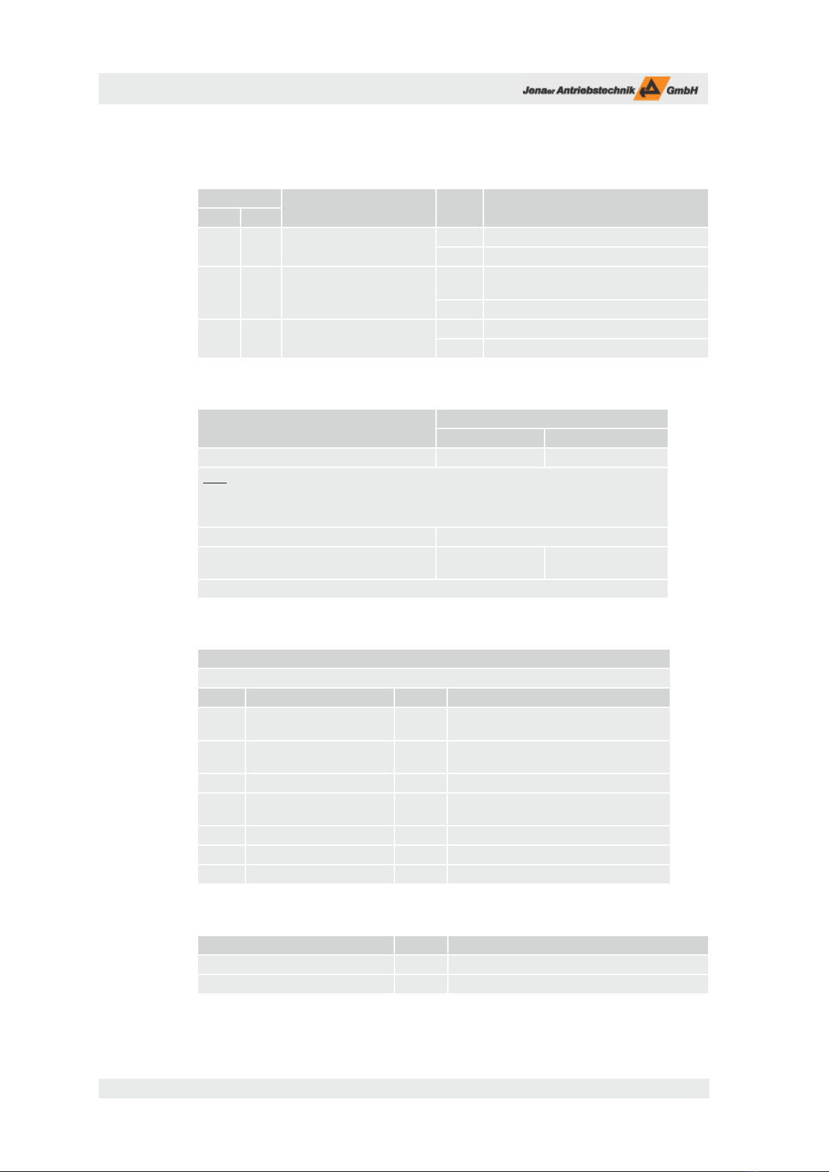
4.2 Rated data of the power stage
Table 4.1: Rated data of the power stage, AC supply at X6
Symb. Rated data Unit
616 AR 616 DR
3-phase AC supply
UNetz Rated supply voltage at AC input connector X6 VAC 3~ 400
(200 ... 528 V)
3~ 400
(200 ... 528 V)
fNLine frequency Hz 49 – 61 49 – 61
SNRated installed load kVA 8,2 8,2
PVN Rated losses W 280 280
UON Rated output voltage1) VAC 390 390
ION Rated output current4) total ARMS 3~ 8 3~ 8 3)
PON Rated output power1) total W 5400 5400 3)
Losses if diverging from nominal load: PV= PV0 + PVI + PVD
PV0 Basic losses W t.b.d. t.b.d.
PVI/IOCurrent-dependent losses per A W/A t.b.d. t.b.d.
PVD/POOutput power-dependent losses per 100 W W/100 W t.b.d. t.b.d.
Power stage
IOP Peak output current2) ARMS 3~ 16 3~ 16 3)
UBUSN Rated DC link voltage VDC 560 560
UBUSP Max. DC link voltage VDC 850 850
UPOvervoltage trip VDC 850 850
CLDC link capacity µF 470 470
EN-P Regenerated capacity Ws 96 96
RB EXT External ballast resistor Ω 40 40
PBP EXT Impulse power ext. ballast resistor kW 17 17
1) The data refers only to the internal data of the servo amplier. Modications of the input voltage due to line supply uctuations are not
taken into consideration. That means that with 15 % less input voltage the output data (UON, PON), on X5 have to be reduced by 15 %.
For motors with a low inductivity the motor dimensioning for the maximum velocity should be 25% to 50% below the specied voltages
(otherwise very high ripple current). For motors with a high inductivity even a higher reduction might be required in order to achieve an
acceptable dynamic performance.
At a heat sink temperature of more than 75 °C or at an ambient temperature of more than 40°C the power stage is switched o.
2) The DC link connection (X4) has no inrush-current limiting. Therefore appropriate circuits have to be integrated in the central power supply.
The power supply also has to be resistant against regenerated energy. It must regulate the DC link voltage during dynamic operation under
the limit UP
. If the regenerating energy (deceleration of the drive) is higher than the energy consumed by all units connected to the DC bus,
the power supply must have a load circuit.
3) For the 2-axis servo amplier ECOVARIO 616 DR the sum of the currents of both axes is listed here. The sharing to the axes can be parame-
terized.
4) Ambient conditions for cabinet dimensioning. The losses PVN refer to nominal operation with IONenn and the maximum output power PDC. In
case of deviations the losses can be estimated as shown here.
Installation and Operating Instructions ECOVARIO® 616, 616 D
16 Subject to change without notice!
4.3 General technical data
Table 4.3: General technical data, control signals
No. Control signal Unit
616 A 616 D
1 1 24 V supply (current draw
without outputs)
V24 ±10 %
A 0.8
8 16 Digital control signal inputs V0 ... 36 (Switching level: L->H: 11 V; H->L: 7 V
acc. to IEC 61131-2 type 3)
mA 10 (at 24 V)
3 6 Digital control signal outputs V 24
A 0.5
Table 4.4: General technical data, external fuses
616 AR 616 DR
AC supply
16 A (characteristic C)
16 A (characteristic C)
Note: When the device is used in an UL environment the overcurrent protection equipment has
to comply to UL489 (current ≤ 13 A) or UL Class CC (current ≤ 15 A, time delay current limiting)!
Alternatively a motor protection switch (self protecting motor controller, certified acc. to UL508,
type E) can be used.
24 V supply max. 12 A (fast)
external ballast resistance (not accessory resistors
DPRxx-xxx)1) t.b.d. t.b.d.
1) The accessory ECOVARIO®resistors DPRxx-xxx are intrinsically safe and therefore do not have to be fused
.
Table 4.5: General technical data, ambient conditions
Ambient conditions
ECOVARIO® is designed for ambient conditions of class 3K3 following EN 50178.
Symb. Condition Unit
TAAmbient temperature during
operation with nominal load
°C 5 – 40
Degree of humidity (not con-
densing)
% R. H. 5 – 85
p Air pressure mbar 860 – 1 060
Cooling the closed cubicle has to be sufficiently ven-
tilated.
h Installation altitude m up to 1 000 without restriction of power
Installation position The technical data refer to a vertical position.
Protection class IP20
Table 4.6: General technical data, dimensions and weight
Dimensions and weight Unit ECOVARIO® 616
Dimensions w x h x d mm 82 x 330 x 225
Weight of unit kg 4.0

Subject to change without notice!
Installation and Operating Instructions ECOVARIO® 616, 616 D
17
4.4 Order key
Table 4.7: Order key ECOVARIO® 6xx
ECOVARIO® x xx x x - x x - xxx xxx
No. of parameter set (three digits)
No. of firmware (three digits)
Approvals
A: CE, standard design
B - I: CE, special design
J: CE, UL, standard design
(UL approval under preparation)
K - Z: CE, UL, special design
(UL approval under preparation))
Type of field bus
A: CAN + RS485 + encoder emulation
B: CAN + RS232 + encoder emulation
F: CAN + RS485 + PROFIBUS DP-V0
G: CAN + RS232 + PROFIBUS DP-V0
H: CAN* + Profinet + RS485
I: CAN* + Profinet + RS232*
K: CAN + Ethernet + RS485
L: CAN + Ethernet + RS232
P: CAN + EtherCAT® + RS485
Q: CAN + EtherCAT® + RS232
Options
R: Safety function„Safe torque off“ (STO)
N: no option
Supply
A: 3-phase AC; 1-axis power stage
D: 3-phase AC; 2-axis power stage
Current rating (rms for 5 s)
16: max. 16 A
Voltage rating (DC bus)
6: max. 600V
Name of the unit
*) CAN/RS232 as service interface for ECO Studio only; no object dictionary acc. to CANopen DS402
Example ECOVARIO® 616 DR-AA-000-000:
ECOVARIO® servo amplier with:
max. 600 VDC DC link voltage
max. 16A output current (total)
AC supply 3-phase, 2-axis power stage
Safety function „STO“
CAN interface + RS485 interface
+ encoder emulation
CE appproval, standard design
Fig. 4.1: Name plate ECOVARIO®, dimensions 70 x 20 mm

Installation and Operating Instructions ECOVARIO® 616, 616 D
18 Subject to change without notice!
4.5 Suitable types of motors
With ECOVARIO® 6xx servo ampliers various types of motors can be operated. Rotative and linear 3-pha-
se motors of the motor series ECOSPEED and ECOLIN® as DC motors can be driven. e motors must be
equipped with encoders for commutation and for position and speed control. Incremental encoders, SIN-
COS encoders and absolute encoders can be evaluated.
It is not possible to drive motors with resolvers as measuring system.
e techical data in this manual refer exclusively to the servo motors mentioned in chap. 4.4.1 and 4.4.2.
If you want to drive DC motors with ECOVARIO® please contact our technical support (see http://www.
jat-gmbh.de/engl/service/service.html)
4.5.1 ECOSPEED motors
e motor series 60C, 80C, 110C and 150C contain rotative, 3-phase
low-pole servo motors with holding torques between 0.5 and 11 Nm.
For technical data and accessories for the motors see our product
catalogue „ECOVARIO®-/ECOMPACT®-/ECOSTEP® Drives“ or
our web site www.jat-gmbh.de
Fig. 4.1: Motor series 60C, 80C and 110C
4.5.2 Direct linear motors ECOLIN®
Series SLM contains iron core, 3-phase, encoder commutated syn-
chronous linear motors from 220 to 1450 N peak force. Series SLME
provides provides ironless direct linear motors from 150 N to 400 N
peak force.
For technical data and accessories of the motors see our product cat-
alogue „ECOVARIO®-/ECOMPACT®-/ECOSTEP® Drives“ or our
web site www.jat-gmbh.de.
Fig. 4.2: Direct linear motors SLM, SLME
4.5.3 DC servo motors
DC motors are not part of the delivery range of the Jenaer Antriebstechnik GmbH but can be operated with
ECOVARIO® ampliers. In this case we recommend strongly to contact our technical service.
e ECOVARIO® supports DC motors with brushes as well as brushless DC servo motors in conjunction
with RS422 compatible standard encoders.

Subject to change without notice!
Installation and Operating Instructions ECOVARIO® 616, 616 D
19
5 Installation
5.1 Mounting
5.1.1 Inportant notes / Informations importantes
Make sure that transport and storage did no damage to the units. /
Veillez à ce que le matériel n’a pas subi de dommages lors du transport ou du stockage.
e ambient air must not be polluted by dust, greases, aggressive gas etc. Eventually appro-
priate countermeasures have to be taken (installation of lters, frequent cleaning). /
L’air de ventilation ne doit pas être souillé (Poussière, graisses, gaz agressifs, etc.). Le cas échéant
prendre les mesures nécessaires intégration de ltres, nettoyage régulier)
e ECOVARIO with STO function has to be mounted in a cabinet which conforms to
protection class IP54 (or in a comparable environment) /
L’ECOVARIO avec fonction STO doit être monté dans une armoire électrique ou un environne-
ment équivalent qui présente un degré de protection minimum IP54.
Depending on the power losses an appropriate ventilation should be provided /
Il faut prévoir une ventilation susante pour compenser les pertes par échauement.
Observe the mounting spaces. / Les espaces libres doivent être respectés.
Use 60/75°C copper wire only. e accessory cables provided by Jenaer Antriebstechnik
fulll these requirements. /
N’utiliser que des câbles à âme cuivre qui résistent à une température de 60/75°C. Les câbles
proposés par Jenaer Antriebstechnik dans son programme d’accessoires, respectent ces exigences.
At installation locations with permanent vibrations or shocks damping measures should be
taken into consideration. /
Dans des implantions exposées à des vibrations continues ou des chocs, il faut vérier si des
mesure de réduction des phénomènes vibratoires doivent être prises.
5.1.2 Dimensions
330 mm
300 mm
375,5 mm
263 mm
15,6 mm
82 mm
225 mm
Fig. 5.1: Dimensions of ECOVARIO® 616 [mm], upper shield optional
330 mm
300 mm
375,5 mm
263 mm
15,6 mm
82 mm
225 mm

Installation and Operating Instructions ECOVARIO® 616, 616 D
20 Subject to change without notice!
5.1.3 Assembly
Basically, ECOVARIO® 6xx is intended for vertical mounting (motor connectors X5A, X5B on the bottom).
In this mounting position devices can be operated with built-in fan unit at ambient temperatures of up to
40°C. e ECOVARIO 6xx with STO function has to be mounted in a cabinet which conforms to protection
class IP54 (or in a comparable environment).
Cable clamps and side metal sheets assure that the connecting cables are laid EMC conform by connecting
the cable shield extensively to chassis earth.
e shields with cable clamps shown in g. 5.3 are available as accessories (see table 9.1). It is important that
the air ow is not disturbed by components above or below the servo ampliers. e distance between the
servo amplifers has to be at least 3 mm.
e surface of the mounting plate has to be conductive (e.g. zinc plated). Varnished mounting plates must
not be used.
INFO /
INDICATION
Make sure that no heat accumulation can
occur in the cabinet.
The servo amplier switches o at too high
temperatures in the cabinet (Error D02 or D03, =>
p. 57, Motor without torque).
Assurez une ventilation forcée suffisante de
l’armoire électrique.
L’amplificateur de servomoteur se coupe en cas de
température trop élevée dans l’armoire électrique
(Erreur D02 ou D03, => p. 57, Moteur sans couple).
Fig. 5.3: Mounting dimensions cabinet, width, minimum spacing [mm]
Kabelkanal
Kabelkanal
300
85
60
60
300 20
60
ECOVARIO®
616/616D
Kabelkanal
ECOVARIO®
616/616D
ECOVARIO®
616/616D
ECOVARIO®
616/616D
85
Cable conduct
Cable conduct
Cable conduct
This manual suits for next models
1
Table of contents
Popular Network Hardware manuals by other brands

NEC
NEC Aspire Series Networking manual

Lab.gruppen
Lab.gruppen NLB 60E Operation manual

Xentino
Xentino A405N Quick installation guide

Extron electronics
Extron electronics IP Link Accessory Power over Ethernet Inserter IPA T... Specification sheet

Ubiquiti
Ubiquiti PowerBeam PBE-5AC-400-ISO quick start guide

Crestron
Crestron Network Device PWE-4803RU installation guide


