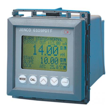
JENCO 6309PDTF User manual

OPERATION MANUAL
JENCO MODEL 6309 PDTF
MICROCOMPUTER BASED
pH/ DO/ Temperature
CONTROLLER
JENCO
ELECTRONICS,LTD
MANUFACTURER OFPRECISIONINSTRUMENTS

1
CONTENTS
Page
a.
INITIAL INSPECTION
a
n
d
ASSEMBLY
2
b.
GENERAL INTRODUCTION 3
c.
USING THE JENCO MODEL 6309PDTF 4
•FRONT PANEL
4
•NORMAL MODE
D
ISPLAY
6
•REA
R
CONNECTORS
8
•TURNING ON/OFF
T
HE
I
NSTRUMENT
1
0
d.
MODEL 6309PDTF
1
1
•NORMAL MODE
1
1
•CALIBRATION/SETTING MODE 11
•PASSWORD CHECK page 13
•USER SETTING page 13
•pH CALIBRATION page 14
Step by step pH calibration 15
•pH CONTROL
S
ETTING page
1
7
•DO CALIBRATION page
1
8
DO CALIBRATION PROCEDURES 19
•DO CONTROL
S
ETTING page
2
0
•CURRENT OUT page 21
•TEMP.
C
ONTROL page
2
2
e.
CONTROLLING
T
HE
R
ELAYS
2
3
•ISOLATION VOLTAGE 23
•OUTPUT LOAD
2
3
•RELAY ACTION, SET POINT & HYSTERESIS 23
•pH RELAYS
2
4
•DO RELAYS
2
5
•TEMPERATURE
R
ELAY
2
6
f.
4-20 mA OUTPUT
2
6
•ISOLATION
V
OLTAGE
2
6
•OUTPUT LOAD
2
6
•pH LINEA
R
OUTPUT
2
6
•DO LINEA
R
OUTPUT
2
8
•pH ANTILOG OUTPUT 28
g.
RS485 INTERFACE
O
PERATION
2
9
•INSTRUCTION
2
9
•PREPARING THE METER 30
h.
ERRO
R
DISPLAYS AND
T
ROUBLESHOOTING
3
1
i.
pH BUFFERS
3
2
X. DO ALTITUDE/PRESSURE
T
ABLE
3
3
a.
SPECIFICATIONS 34
b.
WARRANTY
3
6

2
a.
INITIAL INSPECTION and ASSEMBLY
Carefully unpack the instrument and accessories. Inspect for
damages made in shipment. If any damage is found, notify your
Jenco representative immediately. All packing materials should be
saved until satisfactory operation is confirmed.
MOUNTING PROCEDURE
•Makeacutouton
any panel, with a
thickness of 1/16 in.
(1.5 mm) to 3/8 in.
(9.5mm).
•Removethe
mounting assembly
from the controller
and insert the
controller into the
cutout.
•Replacethe
mounting bracket
assembly onto the controller and secure the controller to the
mounting panel.
Warnin
g
:
If the equipment is used in a manner not specified by the
manufacturer, the protection provided by the equipment may be
impaired.
Cleanin
g
the instrument:
a.
Be sure to remove the power before attempting to clean the
meter.
b.
Use a lint free cloth and clean water or neutral detergent.
c.
Wipe the outer surface of the instrument only.
d.
Wipe‐dry the instrument before powering again.

3
b.
GENERAL INTRODUCTION
The Jenco Model 6309PDTF (pH, DO and Temperature) System is a
rugged microprocessor based instrument assembled in a watertight
¼ DIN case, designed for use in laboratories and process control
applications.
The model 6309PDTF microprocessor allows the user to easily
recalibrate the parameters for the probes. The DO system requires
only a single point calibration, regardless of which dissolved oxygen
display you use. The microprocessor also performs a self‐
diagnostic routine every time you turn on the unit providing you
with basic information about the stability of the instrument.
The system simultaneously displays pH, DO, Temperature, Relay
status and current output in one LCD graphic screen. The LCD also
includes a backlight for low‐lit environments. This system uses
glass electrode for the pH, a “polygraphic clark” membrane for the
DO and a precise thermistor for temperature, providing you with
accurate readings for all your measurements.
The model 6309 PDTF is equipped with 5 relays (2 programmable
High/Low action relays for pH, 2 programmable High/Low relays
for DO and 1 programmable High/Low relay for Temperature); all
relays are hysteresis driven and configurable to CENTER or EDGE
mode. The system also has an isolated 4‐20mA analog output, offset
and span configurable for the pH or DO display.
The model 6309 PDTF comes with a RS485 interface which can
easily let the user log all data (from multiple model 6309 or
6308) with an IBM©PC/AT compatible computer. For

4
advanced users, the model 6309 PDTF may also be remotely
controlled from main display mode to all
calibration/setting
modes.
c.
USING THE
J
ENCO MODEL 6309 PDTF
J
ENCO
6
309PDT
M
ODE
C
AL.
V
IEW
C
URSO
p
H
R
ECAL.
a.
FRONT PANEL
•
The [
MODE/‐(
CURSOR
)] key.
1a. In
Normal
mode this key will change the DO display to DO %
or DO ppm.
1b. In Calibration/Settin
g
mode this key will move to the next
digit of the current active parameter.
1c. In Calibration/Settin
g
mode, pressing this key for two
seconds will move you back to the previous parameter.
•The[
CAL
/
VIEW]key.
2a. Pressing this key for about two seconds, during normal
display mode will switch to Calibration/Setting mode.

5
2b. During Calibration/Setting mode this key will switch to the
next available Calibration/Setting page. Pressing this key at
the last User/Calibration page will return the user to the
normal display mode.
•
The [
]
UP
key.
During Calibration/Setting mode this key will
increment
the
current blinking digit of the active parameter.
•The[
/
pH Recal.]DOWN key.
4a. During Calibration/Setting mode this key will
decrement
the current blinking digit of the active parameter.
4b. During pH calibration, you can press this key to recalibrate
the stand or slope buffer again.
•The[]ENTER key.
During Calibration/Setting mode, this key will save the current
modified parameter and move to the next parameter.
•The[ ]LIGHT key.
This key will turn on or turn off the backlight of the LCD.
The backlight will automaticall
y
turn off if there is no key activity
within two minutes.

6
b.
NORMAL MODE DISPLAY
2
3
4
5
6
7
1
8
9
a.
:
‐ This will be displayed if Calibration/Setting
pages are
p
assword locked meaning the user can’t change the
values unless the correct 4 digit number has been entered.
b.
RELAY:
‐ This will show the status of the relays. At Power‐ON
a“
DISABLED
” message will be displayed for about three
seconds beforegoingto
NORMAL
or
CHECKSTATUS
operation. After exiting the Calibration/Setting pages and the
unit is not password locked, a “
FROZEN
”messagewillbe
displayed for about three seconds before returning to
NORMAL
or
CHECK STATUS
operation. IF no relay is ON then the
“
NORMAL
” message will be displayed. IF any relay is ON then
the “
CHECK STATUS
”willbedisplayed.
c.
CURRENT OUT:
‐Thiswilldisplaytheactualoutputofthe4‐
20 mA output. At POWER‐ON this will show “
OFF
” for about
three seconds before going to normal operation. After exiting
the Calibration /Setting pages a “
FROZEN
” message will be
displayed for about 3 seconds before returning to normal
operation. An “ERROR” display here means that the absolute
difference between 4mA and 20mA is less than 1.0 pH (if pH

7
LINEAR or pH ANTILOG is selected) or less than 1.0 % (if DO
LINEAR is selected and RELAY/mA is set at %) or 0.10 ppm (if
DO LINEAR is selected and RELAY/mA is set at ppm) and that
the current output is disabled.
d.
H,L: ‐ One or both of these annunciators will be displayed if the
left side reading (LARGE FONT DISPLAY) triggered the
respective relay settings. The rightmost character will indicate
RELAY 1 if the display is pH or RELAY 3 if the display is DO The
leftmost character will indicate RELAY2 if the display is pH or
RELAY 4 If the display is DO If the display is DO the
annunciators will only indicate the unit selected at the
RELAY/mA option in the DO CALIBRATION page.
H:
High action relay and the relay is energized.
L:
Low action control and the relay is energized.
e.
LARGE FONT DISPLAY ‐ This reading uses the biggest font and
the reading here is the onl
y
one that will a
ff
ec
t
the analo
g
out
p
ut. You can only select the DO or pH reading to be shown
here by changing the Transmitter Out
p
ut option.
f.
H,L: ‐ One or both of these annunciators will be displayed if the
left side reading (MEDIUM FONT DISPLAY) triggered the
respective relay settings. The rightmost character will indicate
RELAY 1 if the display is pH or RELAY 3 if the display is DO.
The leftmost character will indicate RELAY2 if the display is pH
or RELAY 4 If the display is DO. If the display is ORP the
annunciators will only indicate the unit selected at the
RELAY/mA option in the DO CALIBRATION page.
H:
High action relay and the relay is energized.
L:
Low action control and the relay is energized.
g.
MEDIUM FONT DISPLAY‐this is the secondary reading and

8
no
analog output is supplied.
h.
H,L: ‐ One of these annunciators will be displayed if the
temperature reading triggered the temperature relay setting. The
temperature relay setting can be configured to HIGH or LOW.
H: High action relay and the relay is energized.
L:
Low action control and the relay is energized.
i.
Temperature ‐ the current temperature of the solution.
C. REAR CONNECTORS
Before wiring the probes, relays, analog output, RS485 and power
cord be sure that you are connecting to the right terminal as
shown below (be sure the ac‐plug is not plugged‐in). Remember
that the unit is ON once the user plugs in the power cord to an
AC power supply.

9
A.
Connect the AC line to the rear of the instrument. The model
6309 PDTF can be used with110VAC or 220VAC 50/60 Hz .
Power consumption is 6 watts. Make sure the EARTH
connector is connected to the earth lead of the AC power line.
B.
Connect the proper load to the output relays. Make sure that the
load does not exceed the relay rating, 5 Amp at 115VAC and 2.5
Amp at 230 VAC.
C. Set the proper load to the 4‐20mA‐output connector. Make sure
that the load impedance is less than 500 Ohms.
CAUTION:
MAKE SURE YOU CONNECT THE AC POWER CORD TO THE
CORRECT AC TERMINALS. CONNECTING INCORRECTLY
MAY DAMAGE THE UNIT PERMANENTLY.

10
D. TURNING ON/OFF THE INSTRUMENT
By just plugging the unit to a
correct AC voltage the unit
will be ready for use. There is
no Power key so unplugging
and plugging the unit will
turn OFF or turn ON the unit
respectively.
After the unit is turned on, it
will perform some basic self‐ diagnostics and will display “OK” or
“BAD”. If you received any “BAD” messages turn OFF the unit and
turn it ON again. (See VIII. ERROR DISPLAYS AND
TROUBLESHOOTING).
If the message persists then you might need to call your
distributor. (See XII. WARRANTY).
After the self‐diagnostic is complete the temperature will be
displayed on the lowest part of the screen and you are ready to
make DO or pH measurements. Just immerse the probes halfway
to the liquid. If possible do not allow the probes to touch any
solid object in the solution. There should be no air bubbles
around the probes either. Shaking or moving the probes
vigorously before recording any measurement will dislodge any
bubbles formed in the probes.

11
d.
MODEL 6309 PDTF
A. NORMAL MODE
Turning ON the unit will always
display in normal mode.
The position of pH and DO
display can be switched
depending on the selected
analog output on the CURRENT
OUT SETTING page of the
Calibration/ Setting mode. (See
CALIBRATION
/
SETTING mode)
This instrument is designed
to provide 4 distinct measurements:
A.
Tem
p
erature
‐Currenttemperatureofthesolution,whichis
always displayed
B.
p
H– The degree of acidity or alkalinity of the solution (with
automatic temperature compensation).
C. Dissolved Ox
yg
en % ‐ A measurement of oxygen in percent
saturation.
D. Dissolved Ox
yg
en
pp
m‐ A measurement of oxygen in ppm.
Temperature, pH, and DO (% or ppm) are always simultaneously
displayed in the graphic LCD screen in normal mode. You can
select which DO unit to display by pressing the [
MODE/‐
]key.
B. CALIBRATION/SETTING MODE
Pressing the [CAL/VIEW] key for about two seconds during normal
mode will bring‐up the first page of seven pages of the
Calibration/Settin
g
mode. Pressing [CAL/VIEW]keywillswitchto

12
thenextpageuntilthelastpage,wherepressing[CAL/VIEW]again
will return the user to normal mode.
You can change any blinking words or digit by pressing the [
]or
[
] keys. For options in digit format you need to press the
[
MODE/‐(
CURSOR)
] key to move to the next digit. If you are
satisfied with the selection you made you need to press the [
]
ENTER
key to save the changes and move to the next option. If you
don’t need to change the current blinking option just press the [
]
ENTER
key to move to the next selection.
Below is a simple flowchart showing the path of the [CAL/VIEW]
key:

13
V.
PASSWORD CHECK page ‐
You will only see this
page if the unit is password
locked. To change any
settings or calibration you
need to unlock the system to
remove the “PASSWORD
LOCKED” message. You
need to enter the correct 4‐
digit number on the “ENTER
PASSWORD”input.Youcanstillviewallthepagesof
Calibration/Setting mode ifthesystemispasswordlockedby
just pressing the [CAL/VIEW] key on this page. If the unit is
“PASSWORD LOCKED”goingtoCalibration/Setting mode
will not affect the function of the relays.
CAUTION: If the unit is not locked then every time the user
enters the Calibration/Settin
g
mode the relays and analog out
will be frozen.
VI.
USER SETTING page –
You will only see this page if
the unit is not password locked.
This page is just a warning,
telling you that all relays are
frozen, and that you can calibrate
and change the settings.
NOTE:
FROZEN
MEANS ALL

14
THE RELAYS AND THE ANALOG OUT WILL MAINTAIN
THEIR LAST STATUS UNTIL THE USER RETURNS TO
NORMAL DISPLAY MODE.
VII.
pH CALIBRATION
page ‐ ATC TEMP.–Thecurrent
temperature of the solution.
•
BUFFER 1
‐Inthisoptionyou
can select which buffer to use for
thestandardizationcalibration.
You can choose
7.00
pH or
6.86
pH by using the [
]and[
]
keys and pressing the []keyto
save your choice.
•BUFFER 2 ‐ After you selected the buffer 1 this option will let you
select the second buffer to use to calibrate the slope. You can
choose 4.00pH, 4.01pH, 9.18pH or 10.01pH by using []and[]
keys and pressing the [] to save your choice.
•
STAND
‐ This is the actual pH calibration process, this line will
display the buffer to be used for STAND (OFFSET) calibration,
depending on the choice you made in
BUFFER 1
.(SeeStepby
step pH Calibration)
•
SLOPE
‐ This is part 2 of the pH calibration process, this line will
display the buffer to be used for SLOPE calibration, depending on
the choice you made in
BUFFER 2
.(SeeStepbysteppH
Calibration.)

15
Step by step pH calibration
4.
Press the [CAL/VIEW] key to go to pH Calibration page. If the
unit is password locked, remove the password lock first.
5.
Select buffer 1 (7.00 or 6.86), by using the []or[/pH‐Recal.]
keys, then press the [
] key to save your selection.
6.
Select buffer 2 (4.00,4.01,9.18 or 10.01), by using the []or
[/pH‐Recal.] keys, then press the []keytosaveyour
selection.
7.
Clean the pH electrode and temperature probe with de‐ionized or
distilled water.
8.
Place the pH electrode and Temperature probe into buffer 1.
9.
Press the [
]key.A“
WAIT
” message will blink indicating that
the instrument is waiting for a stable reading. The display will be
locked to the buffer value corresponding to the temperature of
buffer 1 (See
IX.
p
H Buffers
). When a stable reading is reached,
the unit will blink a “
SAVE
” message.
10.
Press the [] key to save the STAND calibration and
prepare to do a SLOPE calibration or press the [/pH‐Recal.]
key to recalibrate buffer 1 and repeat from step 6.
If “OVER”or“UNDER”(SeeVIII. ERROR DISPLAYS AND
TROUBLESHOOTING)isdisplayedorablinking“
SAVE”does
not show after more than few minutes then something is wrong
with your buffer 1 or electrode. Be sure your buffer 1 is correct or
change a new electrode and repeat from step 4.

16
11.
Clean the pH electrode and temperature probe with the
de‐ ionized/distilled water.
12.
Place the pH electrode and Temperature probe into buffer 2.
13.
Press the [
]key.A“
WAIT
” message will blink indicating that
the instrument is waiting for a stable reading. The display will be
locked to the buffer value corresponding to the temperature of
buffer 2 (See
IX.
p
H Buffers
). When a stable reading is reached,
the unit will blink a “
SAVE
” message.
14.
Press the []keytosavetheSLOPEcalibration or press the
[/pH‐Recal.] key to recalibrate buffer 2 and repeat from step 8.
If “OVER”or“
UNDER”(
VIII. ERROR DISPLAYS AND
TROUBLESHOOTING)isdisplayedorablinking“
SAVE”does
not show after more than few minutes then something is wrong
with your buffer 2 or electrode. Be sure your buffer 2 is correct or
change a new electrode and repeat from step 4.
15.
Set‐up your Relay, mA OUT and Temperature control.
16.
The unit is ready for measurement and control.
EFFICIENCY – After saving the SLOPE a new efficiency will be
displayed for about 4 seconds and then will move to the next page.
(Efficiency = (new slope/ ideal slope)* 100%)
We recommend that you use a new electrode, if the electrode
efficiency is lower than 80%.

17
VIII.
p
H CONTROL SETTING page ‐
•
RELAY1
‐Thecontroltypefor
this relay is changeable, you
can choose “
HI
”‐type or “
LO
”
type. (In HI‐type, relay1 will
turn
ON
if the pH is greater
than the RELAY1 setting, in
LO‐type, relay1 will turn
ON
if
the is than
RELAY
settin which
modified by the hysteresis value and hysteresis mode.)(See
section V. CONTROLLING THE RELAYS )Use[
]and[
]to
change the RELAY1 type then press []tosave.Afteryouselect
the RELAY1 type you can now select the RELAY1 setting. Use
[]and[
] keys to change the blinking digit; use the [MODE/‐]
key to select another digit and the [] key to save the new
setting.
•RELAY2 ‐ The control type for this relay is changeable, you can
choose “HI”‐type or “LO” type. (In HI‐type, relay2 will turn ON
if the pH is greater than the RELAY2 setting, in LO‐type, relay2
will turn ON if the pH is less than the RELAY2 setting, which is
modified by the hysteresis value and hysteresis mode.)(See
section V. CONTROLLING THE RELAYS)Use[
]and[
]to
change the RELAY2 type then press []tosave.Afteryouselect
the RELAY2 type you can now select the RELAY2 setting. Use
[]and[
] keys to change the blinking digit; use the [MODE/‐]
key to select another digit and the []keytosavethenew
setting.

18
•
HYSTERESIS(mode)‐ThisisthehysteresismodeforpHRELAY1
and pH RELAY2. You can choose “CENTER” or “EDGE”. (See
section V. CONTROLLING THE RELAYS)
•HYSTERESIS (value) ‐ This is the actual value of the hysteresis.
You can change this value from 0.01pH to 3.99pH. .(
See section
V. CONTROLLING THE RELAYS)
IX.
DO CALIBRATION page ‐
ATC
TEMP.
‐
The current
temperature of the solution.
•
PRESSURE
‐user
changeable pressure, range
from600to1100mBarforDO
computations. If you use
other pressure unit, please
check X. DO ALTITUDE
/
PRESSURE TABLE.
•
SALINITY
‐ User changeable salinity range from 0 to 49.9 ppt for
DO computations.
•
RELAY/mA UNIT
‐ This is the unit which the DO
RELAY3
and
DO
RELAY4
will be based upon. The DO RELAY3 and DO
RELAY4 values for
%
and
pp
m
are saved in different memory
(EEPROM) location.
•CAL VALUE: this is the DO calibration option. If you move the
pointer to this line a flashing [ ] icon will appear. Pressing the
[] ENTER key will start the DO calibration. The unit of this
calibration will depend on the unit of DO at normal mode. To

19
accurately calibrate the model 6309 PDTF/6309PDTF‐1 you will
need the following information:
• The approximate pressure (in mbar) of the region (See section
X. DO ALTITUDE/PRESSURE TABLE)inwhichyouplanto
take your dissolved oxygen measurements.
•
The approximate salinity of the water you will be analyzing.
Fresh water has a salinity of approximately zero. Seawater has a
salinity of approximately 35 parts per thousand (ppt).
DO CALIBRATION PROCEDURES
3.
Connect the DO probe to the unit. Rinse the probe well with
distilled water. For best accuracy, wipe the end of the probe dry.
Do not touch the membrane. Hold the probe in the air gently with
the sensor facing down.
4. Wait around 30 minutes for the dissolved oxygen and
temperature readings to stabilize. Pressing the []ENTER key
will start the calibration.
5. If you are calibrating in % then the 100% calibration will be
displayed. An error will be displayed if the input is not within the
normal DO range. A [] icon will flash, pressing the []ENTER
key will start the calibration. If the input is not within the DO
calibration limit then an error message will be displayed. If all is
well then it will save the new calibration and move to the next
page.
6. If you are calibrating in ppm then the current reading in ppm
will be displayed. If you press the [
]ENTER key, the unit
will capture the current value and then you can change the value
by using the [MODE/‐],[
]UPand[
]DOWNkeys.Ifyouare
Other manuals for 6309PDTF
1
Table of contents
Other JENCO Controllers manuals
