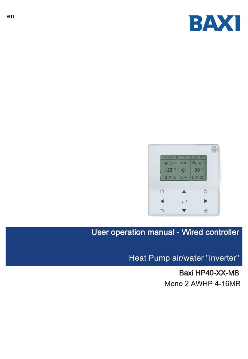
Baxi HP40-XX-MB User manual

Installer operation manual - Wired controller
Heat Pump air/water "inverter"
en
Baxi HP40-XX-MB
Mono 2 AWHP 4-16MR

• This manual gives detailed description of the precautions that should be
brought to your attention during operation.
• In order to ensure correct service of the wired controller, please read this
manual carefully before using the unit.
• For convenience of future reference, keep this manual after reading it.
CONTENTS
1 GENERAL SAFETY PRECAUTIONS 1
• 1.1 About the documentation .................................... 1
• 1.2 For the user ........................................................ 2
2 A GLANCE OF THE USER INTERFACE 3
• 2.1 The appearance of the wired controller............... 3
• 2.2 Status icons......................................................... 4
3 USING HOME PAGES 5
• 3.1 About home pages ............................................. 5
4 MENU STRUCTURE 7
• 4.1 About the menu structure ................................... 7
• 4.2 To go to the menu structure ............................... 7
• 4.3 To navigate in the menu structure ...................... 7
5 BASIC USAGE 8
• 5.1 Screen Unlock .................................................... 8
• 5.2 Turning ON/OFF controls .................................... 9
• 5.3 Adjusting the temperature ................................ 13
• 5.4 Adjusting space operation mode ...................... 14
6 INSTALLATION MANUAL 16
• 6.1 Safety precaution ............................................. 16
• 6.2 Other Precautions ............................................ 18
• 6.3 Installation procedure and matching setting
of wired controller..............................................19
• 6.4 Front cover installation ...................................... 23
7 MODBUS MAPPING TABLE 24
• 7.1 Modbus Port Communication Specication ..... 24

1
Indicates a situation that could result in equipment or property
damage.
1 GENERAL SAFETY PRECAUTIONS
1.1 About the documentation
• The precautions described in this document cover very important topics,
follow them carefully.
• All activities described in the installation manual must be performed by an
authorized installer.
1.1.1 Meaning of warnings and symbols
DANGER
Indicates a situation that results in death or serious injury.
DANGER: RISK OF ELECTROCUTION
Indicates a situation that could result in electrocution.
DANGER: RISK OF BURNING
Indicates a situation that could result in burning because of
extreme hot or cold temperatures.
WARNING
Indicates a situation that could result in death or serious injury.
CAUTION
NOTE
Indicates a situation that could result in minor or moderate injury.
INFORMATION
Indicates useful tips or additional information.

2
• Units are marked with the following symbol:
• Do NOT place any objects or equipment on top of the unit.
• Do NOT sit, climb or stand on the unit.
1.2 For the user
• If you are not sure how to operate the unit, contact your installer.
• The appliance is not intended for use by persons, including children, with
reduced physical, sensory or mental capabilities, or lack of experience
and knowledge, unless they have been given supervision or instruction
concerning use of the appliance by a person responsible for their safety.
Children must be supervised to ensure that they do not play with the
product.
CAUTION
Do NOT rinse the unit. This may cause electric shocks or re.
NOTE
This means that electrical and electronic products may not be mixed with
unsorted household waste. Do not try to dismantle the system yourself: the
dismantling of the system, treatment of the refrigerant, of oil and of other parts
must be done by an authorized installer and must comply with applicable
legislation. Units must be treated at a specialized treatment facility for reuse,
recycling and recovery. By ensuring this product is disposed of correctly, you
will help to prevent potential negative consequences for the environment and
human health. For more information, contact your installer or local authority.

3
2 A GLANCE OF THE USER INTERFACE
2.1 The appearance of the wired controller
Enter the menu
structure from
the home page
Navigate the
cursor on the
display/navigate
in the menu
structure/adjust
the settings
Come back to
the up level
Go to the next step when
programming a schedule in
the menu structure / conrm a
selection/enter a submenu in
the menu structure
Turn on or o the
space operation
mode or DHW
mode turn on or
o the function in
the menu structure
Long press for un-
locking /locking the
controller unlock /
lock some function
such as ‘’DHW
TEMP. ADJUST’’

4
Lock icon Weekly schedule icon
Timer icon
Outdoor ambient temp.
WLAN icon
Domestic hot water
DHW tank temp.
Additional heat source
The solar energy is activated
Tank heater is activated
Error or protection icon
Smart grid icon
The disinfect
function is activated
Turn o
Turn on
At the next scheduled action, the
desired temp. will decrease.
the desired temp.
will not change.
the desired temp.
will increase.
Radiator
The oor heating
Water ow desired temp.
Room desired temp.
Heat mode
Cool mode
Auto mode
Additional heat source
Electric pipe heat source
The compressor is activated
The pumpi is activated
Fan coil
the desired temp.
will decrease.
7
Prevent
freezing mode
is activated
Defrost mode
is activated
Holiday away
/home is
activated
Silent mode
is activated
ECO mode
is activated
Fan coil Radiator The oor heating Domestic hot water
ON
OFF
Free electricity Valley electricity Peak electricity
Smart grid FREE VALLEY PEAK
2.2 Status icons

5
3 USING HOME PAGES
3.1 About home pages
You can use the home pages to read out and change settings that are meant for
daily usage. What you can see and do on the home pages is described where
applicable. Depending on the system layout, the following home pages may be
possible:
• Room desired temperature (ROOM)
• Water ow desired temperature (MAIN)
• Domestic Hot Water (DHW) tank actual temperature (TANK)
home page1
If you have set the WATER FLOW TEMP. as YES and ROOM TEMP. as
NON, the system functions include oor heating and making hot water.
The following page will appear:
NOTE
All the pictures in the manual are shown for explanatory purposes, the actual
screens may dier.
home page2
If you have set the WATER FLOW TEMP. as NON and ROOM TEMP. as
YES, the system functions include oor heating and making hot water. The
following page will appear:
NOTE
The wired controller should be installed in the oor heating room to check
the room temperature.

6
home page3 :
If the DHW MODE is set NON , and if ‘’WATER FLOW TEMP.’’ is set YES,
‘’ROOM TEMP.’’ is set YES,There will be a main page and an additional one.
The system functions include oor heating and space cooling for fan coil,
home page 3 will appear:
MAIN
PAGE
ADDITIONAL
PAGE
2

7
ADDITIONAL
PAGE
4 MENU STRUCTURE
4.1 About the menu structure
You can use the menu structure to read out and congure settings that are
NOT meant for daily usage. What you can see and do in the menu structure
is described where applicable.
4.2 To go to the menu structure
From a home page, press ‘’MENU’’. Result: The menu structure appears:
4.3 To navigate in the menu structure
Use’’▼’’、 ‘’▲’’ to scroll.
home page4 :
If the DHW MODE is set YES. There will be a main page and an
additional one. The system functions include oor heating, space
cooling for fan coil and domestic hot water, home page 4 will appear:
MAIN
PAGE
MENU
OPERATION MODE
PRESET TEMPERATURE
DOMESTIC HOT WATER(DHW)
SCHEDULE
OPTIONS
CHILD LOCK
ENTER
MENU
SERVICE INFORMATION
OPERATION PARAMRTER
FOR SERVICEMAN
WLAN SETTING
ENTER
2

8
5 BASIC USAGE
5.1 Screen Unlock
If the icon is on the screen, the controller is locked.
The following page is displayed:
Press any key, the icon will ash. Long press the key. The
icon will disappear, the interface can be controlled.

9
• Use the interface to turn on or o the unit for space heating or cooling.
The ON/OFF of the unit can be controlled by the interface if the ROOM
THERMOSTAT is NON. (See ‘’ROOM THERMOSTAT SETTING’’ in
«Installation, User and Service Manual»).
• Press ‘’◄ ‘’、 ‘’▲’’ on home page,the black cursor will appear:
Long press
Long press
The interface will be locked if there is no handing for a long time(about 120
seconds) If the interface is unlocked, long press , the interface will be
locked.
5.2 Turning ON/OFF controls

10
1 ) When the cursor is on the temperature of space operation mode side (In-
cluding heat mode , cool mode and auto mode ), press key to
turn on/o space heating or cooling.
If the TEMP. TYPE is set ROOM TEMP., the following pages will display:
If the DHW TYPE is set NON,the following pages will display:
OFF

11
Use the room thermostat to turn on or o the unit for space heating or cooling.
①The room thermostat is set to YES(see ‘’ROOM THERMOSTAT SETTING’’
on «Installation, User and Service Manual») the unit is turned on or o by the
room thermostat, press on the interface, the following page will display:
Turning on or o cooling/ heating
mode is controlled by the room
thermostat. Please turn on or
o cooling/ heating mode by the
room thermostat.
CONFIRM
②DUAL ROOM THERMOSTAT is set YES(see ‘’ROOM THERMOSTAT
SETTING’’ in «Installation, User and Service Manual»). The room thermostat
for fan coil is turned o ,the room thermostat for the oor heating is turned
on,and the unit is running, but the display is OFF. The following page is
displayed:
2
2
OFF

12
If the space operation mode is OFF,the following pages will display:
Use the interface to turn on or o the unit for DHW.Press ‘’►’’、 ‘’▼’’on home
page,the black cursor will appear:
2)When the cursor is on DHW operation mode. Press key to turn on/o
the DHW mode.
If the space operation is ON,the following pages will display:

13
• If the cursor is on the temperature, use the ‘’◄’’、‘’►’’ to select and use
‘’▼’’、 ‘’▲’’ to adjust the temperature.
5.3 Adjusting the temperature
Press ‘’◄‘’、 ‘’▲’’ on home page, the black cursor will appear:

14
5.4 Adjusting space operation mode
• Adjusting space operation mode by interface. Go to ‘’MENU’’ > ‘’SPACE
OPERATION MODE’’ . Press , the following page will appear:
15
OPERATION MODE
Operation mode setting:
HEAT
CONFIRM
AUTOCOOL
A
23
2

15
• There are three modes to be selected including HEAT, COOL and AUTO
mode. Use the ‘’◄’’,‘’►’’ to scroll, press to select. Even if you don’t
press button and exit the page by pressing button, the mode would
still eective if the cursor have be moved to the operation mode.
If there is only HEAT(COOL) mode, the following page will appear:
• The operation mode can not be changed see cool MODE SETTING on
Installation, User and Service Manual.
OPERATION MODE
Operation mode can only be set
heat mode:
CONFIRM
HEAT
CONFIRM
COOL
If you
select…
heat
cool
A
auto
Then the space operation mode is
Always heating mode
Always cooling mode
Automatically changed by the software based on the
outdoor temperature (and depending on installer settings of
the indoor temperature), and takes monthly restrictions into
account.
Note: Automatic changeover is only possible under certain
conditions.
See the FOR SERVICEMAN> AUTO MODE SETTING in
«Installation, User and Service Manual».
OPERATION MODE
Operation mode can only be set cool
mode:

16
• Adjust space operation mode by the room thermostat, see ‘’ROOM
THERMOSTAT’’ on «Installation, User and Service Manual».
Go to MENU>OPERATION MODE, if you press any key to select or adjust,
the following page will appear:
6 INSTALLATION MANUAL
6.1 Safety precaution
• Read the safety precautions carefully before installing the unit.
• Below statements are important safety issues that must be obeyed.
• Conform there is no abnormal phenomena during test operation after
completion, then hand the manual to the user. Meaning of marks:
Cool/heat mode is controlled by
the room thermostat.
Please adjust the operation mode by
the room thermostat.
CONFIRM
WARNING
Means improper handling may lead to personal death or severe
injury.
CAUTION
Means improper handling may lead to personal injury or property
loss.

17
Please entrust the distributor or professionals to install the unit.
Installation by other persons may lead to imperfect installation,
electric shock or re.
Strictly follow this manual.
Improper installation may lead to electric shock or re.
Reinstallation must be performed by professionals.
improper installation may lead to electric shock or re.
Do not disassemble your unit at will.
A random disassembly may cause abnormal operation or heating,
which may result in re.
Do not install the unit in a place vulnerable to leakage of
ammable gases.
Once ammable gases are leaked and left around the wired
controller, re may occur.
The wiring should adapt to the wired controller current.
Otherwise, electric leakage or heating may occur and result in re.
The specied cables shall be applied in the wiring. No external
force may be applied to the terminal.
Otherwise, wire cut and heating may occur and result in re.
Do not place the wired remote controller near heat sources*,
to avoid the remote signal of the controller to be disturbed.
*fireplace, heaters, lamps, candles, direct sunlight
WARNING
CAUTION

18
6.2 Other Precautions
6.2.1. Installation location
Do not install the unit in a place with much oil, steam, sulfide gas.
Otherwise, the product may deform and fail.
Install in the room where the user spends most of their time, in a
draught-free environment.
Check that the distance between the thermostat and the appliance does
not exceed 50 meters (maximum cable length).
6.2.2 Preparation before installation
1) Check whether the following assemblies are complete.
6.2.3 Note for installation of wired controller:
1) This installation manual contains information about the procedure of
installing Wired Remote Controller. Please refer to the Installation, User and
Service Manual» of the outside unit for connection between Wired Remote
Controller and Indoor Unit.
2) Circuit of Wired Remote Controller is low voltage circuit. Never connect it
with a standard 220V/380V circuit or put it into a same Wiring Tube with the
circuit.
No. Name Qty. Remarks
1 Wired Controller 1
2Cross round head wood
mounting screw 3 For Mounting on the Wall
3Cross round head
mounting screw 2For Mounting on the
Electrical Switch Box
4Installation, User and
Service Manual 1
5 Plastic bolt 2
This accessory is used when
install the centralized control
inside the electric cabinet
6 Plastic expansion pipe 3 For mounting on the Wall
Table of contents
Other Baxi Controllers manuals