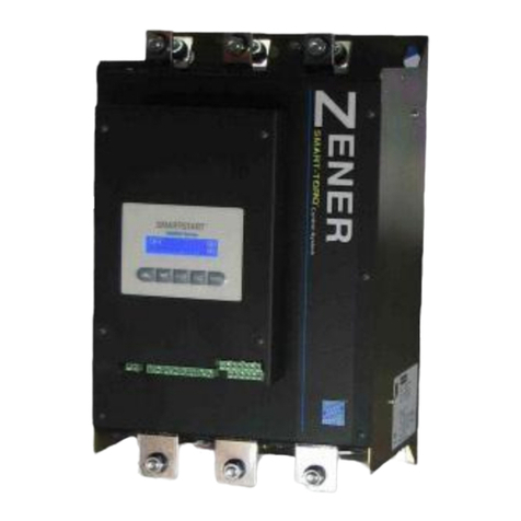
Zener SMARTSTART 6000 User manual

ZENERVARIDRIVESOLUTIONS
ZENERSMARTSTART®6000
SoftStarterInstructionManual


InstructionManual:Smartstart®6000IMI0042revK
Contents
Introduction 2
Receiving………2
Handling&Storage………2
HandlingonInstallation………2
Software………2
TheSmartstart®60003
SoftStarterOperation………3
‘SMART‐TORQ’TorqueControl………3
Installation4
MechanicalInstallation………4
HeatDissipation&ventilation………4
MechanicalDimensions………5
PowerWiring‐General………6
SemiconductorFuses………6
PowerWiring–15A‐80A………7
PowerTerminals–100Aandabove………8
PowerTerminals–6wire&CTrelocation………10
ControlWiring………13
Communications………15
Programming16
LocalControlPanel/Display………16
TripLog/Resetting………18
MenuMap………19
1Setupmenu–Display(D01‐D20)………20
2Setupmenu–Motor(M01–M04)………21
3Setupmenu–Control(C01‐C22)………21
4Setupmenu–Protection(P01‐P73)………23
5Setupmenu–Reset(R01‐R13)………26
6Setupmenu–Input(X10‐X22)………27
7Setupmenu–Output(Y10‐Y52)………27
8Setupmenu–Advanced(A10‐A61)………29
9Setupmenu–Network(N01‐N20)………31
10Setupmenu–Commands ………32
11Setupmenu–StarterDiagram………32
12Setupmenu–NetworkDiagram………33
Relayfunctions,I/Ofunctions,
Alarm&TripMessages……...34‐36
BrakefailProtection………37
Specifications………38
ThermalProtection………39
Unitratings………40
Shipping/PackagingDetails………41
Options………42
Appendix–
A–Smart‐Torque/Typicalstartparameters………44
B‐ApplicationDiagrams………46
C–RemoteConsoleInstructions……..49
D–DataLoggerOptionBoard…….50
E–6WireusinginternalCT’s…….52
SetupRecordSheet………53
Read&familiariseyourselfwiththewarnings
detailedonPage1ofthemanualbefore
proceeding.
Readalloperatinginstructionsbeforeinstalling,
wiring,operating,servicingorinspectingthe
Smartstart.Ensurethattheinstructionmanualis
madeavailabletothefinaluseroftheproductas
wellasallpersonnelinvolvedinanyaspectof
installation,adjustmentormaintenance.
Thissymbolidentifiestheessentialparametersfo
r
quicksetup.
(High Voltage Warnin
g
)
(General Warning)

IMPORTANT – Read this first !!
InstructionManual:Smartstart®6000IMI0042revK
Page1
Readalloperatinginstructionsbeforeinstalling,wiring,operating,servicingorinspectingtheSmartstart®6000.Ensurethat
theinstructionmanualismadeavailabletothefinaluseroftheproductaswellasallpersonnelinvolvedinanyaspectof
installation,adjustmentormaintenance.
YourSmartstart®6000mustbeappliedandinstalledbyasuitablyqualifiedandexperiencedelectricaltradespersonin
accordancewiththismanual,goodengineeringpracticeandalllocalrulesandregulations.
TherearehazardousvoltagesinsidetheSmartstart®6000wheneveritisconnectedtoanelectricalsupply.
TheSmartstart®6000containshighenergycircuitsthatmaybehazardous.Donotoperatewiththecoversremovedorthe
doorsoftheenclosureinwhichitisinstalledopen.DonottouchtheterminalsoftheSmartstart®6000oranyassociated
motorandwiringwhenitisenergised,eveniftheSmartstart®6000andmotorarestopped.Electricshockmayresult.
Donotmodifythisequipmentelectrically,mechanicallyorotherwise.Modificationmaycreatesafetyhazardsaswellas
voidingtheULlistingofmodelssolisted.
TheSmartstart®6000isdesignedtodriveanappropriatelyratedandotherwisesuitable3phaseinductionmotor.Itisnot
suitableforsinglephasemotorsorothertypesofmotorornon‐motorload.Usewithinappropriateloadtypesmaycreate
asafetyhazard.
WheretheSmartstart®6000isusedasacomponentpartofanotherproduct,itisthepurchaser'sresponsibilitytoensure
thatthefinalproductmeetsallofthenecessarysafety,EMC,regulatory,operationalandotherrequirementsforthat
product.Requirementsforthepurchaser'sfinalproductmaybesubstantiallydifferenttotherequirementsforstand‐
aloneinverters.
TheSmartstart®6000isintendedforuseonlyinfixedwiringapplications.Itisnotintendedforuseonaflexiblesupply
cable.
MounttheSmartstart®6000onavertical,incombustiblesurfacesuchasmetalormasonry.Donotplacecombustibleor
flammablematerialneartheSmartstart®6000.Failuretoobservetheseprecautionsmaycreateafirehazard
TheSmartstart®6000ismanufacturedunderstrictqualitycontrolarrangements,howeveradditionalandindependent
safetyequipmentmustbeinstallediftheapplicationissuchthatfailureoftheproductmayresultinpersonalinjuryor
propertydamage.
EnsuretheSmartstart®6000isappliedinamannerthatdoesnotadverselyaffecttheproperoperationofother
equipmentorsystems,particularlythosethathaveasafetyfunction.
InstallemergencystopcircuitrythatremovespowerfromtheSmartstart®6000anddoesnotdependonanyfeatureofthe
productforproperandsafeoperation.
TheSmartstart®6000hasfeaturesthatmaybeusedtocauseanautomaticrestartincertaincircumstances.Theoverall
application(machineetc)mustbedesignedsuchthatautomaticrestartisnothazardous.
Donotinstallthisequipmentinlocationswheremechanicaldamagetotheenclosureispossible.Inparticular,consider
vehicles,vandalismandattackbyinsectsoranimals.Severeequipmentdamageandsafetyhazardsmayresult.
TheSmartstart®6000offersanEssentialServicesOver‐ride(ESO)modeofoperation.Thismodeofoperationintentionally
ignoressomemotorandstarterprotection.Asaresulttheequipmentmayoperateoutsideitsthermalratingandvoid
anywarranty.

Introduction
InstructionManual:Smartstart®6000IMI0042revK
Page2
Receiving:
InspecttheSmartstart®6000foranyshippingdamage.Ifany
damageisfound,reportittothecarrierimmediately.
Removecoverofstarterandvisuallycheckfordamage.
DonotattempttooperatetheSmartstart®6000ifany
obviousdamageexistsorsuspectdamagehasoccurred.
Aftertheinitialinspection,theSmartstart®6000canbe
repackedandstoredinaclean,drylocationuntilitis
requiredforuse.
Handling&Storage:
Toensurethestarterisprotectedbeforeinstallation,
handleandstoretheequipmentinitspackaging.
DONOTstorethisequipmentinanareawherethe
ambienttemperaturewillfallbelow‐20ºCorriseabove
70ºC.DONOTstorethisequipmentinareasthatare
subjecttocondensationorcorrosiveatmosphere.Proper
storageisnecessarytoensuresatisfactorystartupand
performance.
HandlingonInstallation:
TheSmartstart®6000rangecomprises5sizeswithvarious
weightsanddimensions.
Anappropriatehandlingdevicemustbeusedwithlarge
starters.‘Handlingpoints’havebeenprovidedtoaid
lifting.
Theprecautionsdescribedbelowmustbefollowed:
DONOThandlethestarterbythepower
terminals/busbar.
Usehandlingpointswhereprovidedto
liftlargerunits.
Software:
ThismanualappliestotheSmartstart®6000series
softwarerevisionV1.31.TheSoftwarerevisioncanbe
viewedonthe‘DashBoard’(Display)oftheStarter.

TheSmartstart6000
InstructionManual:Smartstart®6000IMI0042revK
Page3
BasicSoftStarterOperation
TheZenerSmartstart®6000isareducedvoltagecontroller
designedforstartingstandard3Phaseinductionmotors.
Theunitissolidstate,usingamicroprocessortocontrol
inverseparallel(backtoback)pairsofSCR’s.
AnSCR/thyristorisasemiconductordevicethatlatches
whentriggered.Oncetriggereditallowscurrenttoflow
inonedirectiononlyandturnsoffatzerocurrent.
ThefiringangleoftheSCR’sarecontrolledtoachievethe
desiredaccelerationofthemotor.
SoftStartersprovidethefollowingbenefits:
1. Reducedstressesandwearonthe
mechanicsofthesystem
2. Reducedstartingcurrents
3. Minimizevoltagedipsonthesupply
4. LoweredPeakdemandcharges
5. Eliminatebeltslippageonfans
6. Smoothaccelerationofmotor/load
SMART‐TORQ®TorqueControl
TheZenerSmartstart®6000incorporatesaclosedloop
torquecontrolsystemtoprovidebettercontrolover
starting&stopping3phaseinductionmotors.
Conventionalvoltagerampcontrolsystemstypically
producelowtorqueatlowspeeds.Whenstarting&
stoppingvariabletorqueloads(e.gPumps)thiscan
resultsinaveryrapidaccelerationordecelerationwitha
nonlinearchangeinmotorspeed.
TheSmartstart®6000seriesovercomestheseissuesby
regulatingthetorqueinthemotortomatchtheload
typeduringtheacceleration&deceleration.This
essentiallyallowsaconstanttorquetobeproducedin
themotor.Thecontinualmonitoringofthemotor
characteristicsduringtherampalsoallowsinstantaneous
adjustmentofthestarteroutputtoallowforchangesin
loadconditions.
The‘SMART‐TORQ®’controlsystemprovidessmooth
starting&stopping,allowingrampprofilingtoproducea
linearaccelerationanddecelerationofthemotorspeed.
Therearemanybenefitswithvariabletorqueloads(such
aspumpsandfans)byachievingalinearrampprofileand
greatercontroloverdeceleration.Withpump
applicationsthisprovidesbettercontroltominimize
waterhammerproblems.
SMART‐TORQBenefitsinclude:
1. Atruelinearaccelerationoftheloadandmotor
forallloadtypes.
2. Reducedpeakinrushstartingcurrents.
3. Reducedstressesandwearonthemechanicsof
thesystem
4. Rampprofilingtobettermatchtypeofloadsuch
asvariabletorqueloads.Bettercontrolof
pumpsandfans,withoutrapidinitialrampbut
linearramp.
5. Reducedheatinginmotoratlowspeeds.
6. Noinstabilityduetochangingpowerfactor.
Closedloopsystemtomonitorandreactto
changingpowerfactor.
7. Noinstabilityduetoslotripplein3wireand6
wireoperation.
8. Bettercontrolofdecelerationthroughclosed
looptorquecontrolsystem.
TheSmartstart®6000offersuseraccesstorampprofiling
parameterstofinetunetheTorqueControlSystemto
achievemoreapplicationspecificperformance
requirements.SeePage44formoreinformation.

Installation‐Mechanical
TechnicalManual:Smartstart®6000IMI0042revK
Page4
MechanicalInstallation
TheSmartstart®6000shouldbeinstalledbyqualified
electricalpersonnelonly.Thefollowingshouldbe
consideredwheninstalling.
Mountinavibrationfreeenvironment.
Mountverticallyandawayfromheatradiating
sources.
Donotmountindirectsunlightoronhotsurfaces.
Mountinasuitableenclosurefortheenvironment
inwhichitistooperate,thetotalheatdissipation
mustbeconsidered.
DonotdrillholesintotheSmartstart®6000
enclosure.
Donotallowmetalshavingsoranyother
conductivematerialtoentertheenclosureor
damagemayresult.
Clearancesforairflow:
Models:6R15/30/60/80Only:
BelowillustratestheclearancestoallowaccesstoPortsif
fitted;
i) RemoteConsole(RJConnection)
ii) SDCardSlot
iii) EthernetPort
HeatDissipation
TheSmartstart®6000iscooledbytemperaturecontrolled
internalfans.Installingabypasscontactorwillreducethe
heatdissipatedandtheventilationrequired.SoftStarters
generallydissipateapproximately4.5wattsperAmp
whenoperatedwithoutabypasscontactor.
Theheatdissipatedcanbecalculatedby;
ContinuousDuty:
P =(FLCx4.5)
BypassDuty:
P=(FLCxSCx4.5xtxN)/3600
Where;
P=PowerdissipatedinWatts
FLC=NameplateFLCofMotor
SC=Averagestartingcurrent
expressedperunitofFLC
t=Startingtime
N=Numberofstartsperhour
WheninstallingtheSmartstart®6000inanenclosureor
switchboarditisnecessarytoconsidertheheat
dissipatedandthentheventilationrequired.
Thefollowingformula’swillassistindetermining
whetherventilationisrequiredandhowmuch.
VentilatedEnclosure:
V=(3.1xP)/T
Where;V=Airflowrequiredinm3/hour
P=PowerdissipatedinWatts
T=Temperaturedifferentialin°C
(inside–outside)
NonVentilatedEnclosure:
A=P/(Txk)
Where;A=Exposedsurfaceareaofcabinet(m2)
P=PowerdissipatedinWatts
T=Temperaturedifferential(°C)
(inside–outside)
k=Heattransmissionconstant
(5forPaintedmetal)
> 75mm
> 75mm
> 20mm
> 75mm
> 75mm

Installation‐Mechanical
TechnicalManual:Smartstart
®
6000IMI0042revK
Page5
Dimensions
(AllDimensionsinmm)
MountingHoles:
MountingHoles:
MountingHoles:
Model:ChassisABC D Depth
6R005B2B2335162315 111 174
6R015B2B2335162315 111 174
6R030B2B2335162315 111 174
6R060B2B3440162420 111 174
6R080B2B3440162420 111 174
Model:ChassisA BC D Depth
6R10000A2430248400 216 244
6R19000A2430248400 216 244
6R22000A2430248400 216 244
6V09000A2+430248+55400 216 244
Model:ChassisABC D Depth
6R36000A3670375640 159 285
6R58000A3670375640 159 285
6R83000A3670375640 159 285
6V20000A3+670375640 159 305
6V40000A3+670375640 159 305

Installation‐PowerWiring
TechnicalManual:Smartstart
®
6000IMI0042revK
Page6
PowerWiring
TheZenerSmartstart®6000isinstalledbetweenthe
mainsandcabletothemotor.Ifamainsorisolation
contactorisuseditisbestcontrolledbythestarters
‘Linerelay’.
3Wireor6wire:Thestandardconnectionofan
electronicsoftstartertoamotoris3wire.
Analternativeconnectionis6wireorinsidedelta
connection.Thisiscommonlyusedwhenreplacinga
star/deltatypemotorstarter.
Bypass/Continuous:TheSmartstart®6000can
operatewithorwithoutabypasscontactor.Some
modelsincludeanintegralbypasscontactor.The
bypasscontactorreducestheheatdissipationofthe
softstarterasthesemiconductorsarebypassedafter
theramptime.
Selectcables&installincompliancewith
localregulations
MotorProtection:
TheSmartstart®6000providesadvancedmotor
protectionwithuserselectableoverloadclasses,over
&undercurrentprotection,phaseimbalanceand
thermistorprotection.Itisimportantthatthepower
wiringisfollowedcorrectlytoensureproper
protectionandstarterperformance.
Refertopage23‐26and39formoredetailsregarding
motorprotection.
SemiconductorFuses
Semiconductorfusesarerecommendedforall
electronicsoftstarterstoprovideprotectionofthe
thyristorsintheeventofanoutputshortcircuit.
Semiconductorfusesarestronglyrecommendedfor
applicationssuchassubmersiblepumps.
Semiconductorfusesareoptionalwithallmodels.
Forsmallermodels(15–80Amp)fusekitsare
available.
Forlargermodelssemiconductorfusekitsare
availablewhichmounttothe‘Line’Busbar.
Refertopage43formoredetailsonsemi‐
conductorfuses.

Installation‐PowerTerminals
(upto80Amp)
TechnicalManual:Smartstart
®
6000IMI0042revK
Page7
3WirewithintegralBypass
OnlyModels;6R015B2&6R005B2
6R030B2
6R060B2
6R080B2
PowerTerminations
Model:MaxcablesizeTightening
Torque
6R005B26mm21.5–1.8Nm
6R015B26mm21.5–1.8Nm
6R030B26mm21.5–1.8Nm
6R060B235mm23.2–3.7Nm
6R080B235mm23.2–3.7Nm
EarthM6stud‐
SemiconductorFusekit(Optional)
RefertoPage43forselection.
SemiconductorFuseReplacement
RefertoPage43forreplacementfuses.
Refer to page 13-14
For Control Wiring
(1) OptionalFastActingSemiconductorFusesselectedtosuitthe
SCRdevicesused.
(2) LineContactorcontrolledbytheSoftStarter.
(seeControlwiringonPage13&14andapplicationdrawings
onPage46‐48)
(3) Models6R5to6R80includeanintegralBypassContactor.With
thesemodelsanexternalbypasscontactorisnotrequired.

Installation‐PowerTerminals
(100Amodelandabove)
TechnicalManual:Smartstart
®
6000IMI0042revK
Page8
PowerTerminations
(Allsoftstartersincludeaboltkit)
ChassisA2:
ChassisA3:
SemiconductorFusekit(Optional)
FusekitincludesFusesandadditionalbusbar
Model:DescriptionPartNo.
6R10000FuseKittosuit6R100TQ60025
6R19000FuseKittosuit6R190TQ60026
6R22000FuseKittosuit6R220TQ60027
6R36000FuseKittosuit6R360TQ60028
6R58000FuseKittosuit6R580TQ60029
6R83000FuseKittosuit6R830TQ60030
SemiconductorFuseReplacement
Model:DescriptionPartNo. Qtyper
Starter
6R10000SemiconductorFuse(200A)TF22200 3
6R19000SemiconductorFuse(400A)TF22400 3
6R22000SemiconductorFuse(400A)TF22400 3
6R36000SemiconductorFuse(630A)TF23630 3
6R58000SemiconductorFuse(500A)TF23500 6
6R83000SemiconductorFuse(700A)TF23700 6
Model:ChassisBusbarHoleBoltSize EarthStud
6R10000A21x8.5mmM8 M8
6R19000A21x10.4mmM10 M8
6R22000A21x10.4mmM10 M8
6V09000A2+1x8.5mmM8 M8
6R36000A32x10.4mmM10 M8
6R58000A32x10.4mmM10 M8
6R83000A32x10.4mmM10 M8
6V20000A32x10.4mmM10 M8
6V40000A32x10.4mmM10 M8
6V60000A42x10.4mmM10 M8

Installation‐PowerWiring
(100Amodelandabove)
TechnicalManual:Smartstart
®
6000IMI0042revK
Page9
3WireBypass
3WireContinuous
(WithoutBypassContactor)
NOTE:TheSS6000musthavetheappropriateratingto
operatewithoutabypasscontactor.
Refertopage13&14
ForControlWiring
Refertopage13&14
ForControlWiring
(1) OptionalFastActingSemiconductorFusesselectedtosuitthe
SCRdevicesused.
(2) LineContactorcontrolledbytheSoftStarter.
(seeControlwiringonPage13&14andapplication
drawingsonPage46‐48)
(3) BypassContactorcontrolledbytheSoftStarter.
(seeControlwiringonPage13&14andapplication
drawin
g
sonPa
g
e46‐48
)
(1) OptionalFastActingSemiconductorFusesselectedto
suittheSCRdevicesused.
(2) LineContactorcontrolledbytheSoftStarter.
(seeControlwiringonPage13&14andapplication
drawingsonPage46‐48)

Installation‐PowerWiring
(100Amodelandabove)
TechnicalManual:Smartstart
®
6000IMI0042revK
Page10
Using6wireConfiguration
TheSmartstart®6000canbeconfiguredtooperatein
6wiremode.6wiremodemaybethepreferred
methoddueto:
1. Possiblereductioninthesizeofstarterrequired,
savingonspaceand/orcost.
2. Wiringmayalreadybepresentifastart/deltatype
starterwaspreviouslyused.
3. Reducedmotorcablesize.
ThemajoradvantageisthatthecurrentintheSCRis
58%lessthanitwouldbeforthesamemotor
connectedin3wire.Thediagrambelowillustrates
howthemotorisconnectedin6wire,alsoknownas
insidedelta.
Thefollowingillustratesthedifferencebetween3wire&6
wireconnection:
CurrentMonitoring&TorqueControl:
ForthetorquecontroltooperatecorrectlytheC.T’sneed
tomonitorthe‘line’currentandnotthe‘Phase’currents.
ForthisreasontheC.T’snormallysuppliedinternally,need
toberelocatedexternaltothesoftstarter.
ItiscriticalthattheC.T’sbeinstalledinthecorrectphase
andinthecorrectdirection.Page12providesinstructions
astowheretheC.T’saretobelocated.
Refertopage12
FordetailsoncorrectlyinstallingexternalC.T’s
InsomecasestheCT’scanbeinternal
.
RefertoAppendixEonpage52for
details

Installation‐PowerWiring
(100Amodelandabove)
TechnicalManual:Smartstart
®
6000IMI0042revK
Page11
Standard6wireBypass
Standard6wireContinuous
Refertopage13&14
ForControlWiring
Refertopage13&14
ForControlWiring
Refertopage12
Fordetailsoncorrectlyinstallin
g
externalC.T’s
Refertopage12
Fordetailsoncorrectlyinstallin
g
externalC.T’s
(1) OptionalFastActingSemiconductorFusesselectedtosuittheSCR
devicesused.
(2) LineContactorcontrolledbytheSoftStarter.
(seeControlwiringonPage13&14andapplicationdrawingson
Page46‐48)
(3) BypassContactorcontrolledbytheSoftStarter.
(seeControlwiringonPage13&14andapplicationdrawingson
Pa
g
e46‐48
)
(1) OptionalFastActingSemiconductorFusesselectedto
suittheSCRdevicesused.
(2) LineContactorcontrolledbytheSoftStarter.
(seeControlwiringonPage13&14andapplication
drawingsonPage46‐48)

Installation‐PowerWiring
(100Amodelandabove)
TechnicalManual:Smartstart
®
6000IMI0042revK
Page12
RelocatingtheInternalCurrent
Transformersfor6wireoperation.
TheSmartstart®6000comesstandardwithinternal
CurrentTransformers(C.T’s)formonitoringthe
currentduringacceleration,decelerationandwhenin
bypass.
ItisimportantthattheSmartstart®6000bewiredina
mannertoensuretheC.T’sarealwaysmonitoringthe
motorcurrent.Forthisreason9terminalsare
provided.Thisisimportanttoensurecontinual
protectionofthesoftstarter,themotorandtheload.
ThecorrectinstallationoftheC.T’siscrucialfor
optimumperformanceofthetorquecontrolsystem.
In6wireoperation,itisnecessarytorelocatetheC.T’s
externaltothestarter.For6wireoperationtheC.T’s
aretobeinstalledontheincominglinesupplycables
sothatthelinecurrentismonitored(notthephase
currents).
TheSmartstart®6000mustbepurchasedwithC.T’s
externalbyordering‘preparedfor6wire’;
Partno.Description:
TF60015Preparefor6wire:6R100‐220
TF60016Preparefor6wire:6R360‐830
NOTE:6WireusingInternalCT’s
InsomecasestheCT’smayremaininternal.Thisissubject
totheMotorFLCandtheSoftStarterRating.Referto
AppendixEPage52formoredetails.
InstallationofexternalC.T’s
WhenrelocatingtheC.T’sexternaltothesoftstarterit
isimportanttoensurethefollowing:
1. C.T’sareinstalledonL1&L3
2. C.T’sareinstalledincorrectdirection
P1label=lineside
3. C.T’sareterminatedwithcorrectphasing.
S1=Red
S2=Black
TheC.T’ssuppliedwiththeSmartstart®6000hasa
labelwhichshowsthecorrectphaseanddirection.
IftheC.T’sarenotinstalledcorrectlythestarterwill
displayafaultora‘C.TPhaseerror’.
Programming:
Programthestarterfor3wireor6wireoperation.The
selectionavailablefor6wireis‘Standard6wire’or
‘alternate6wire’,dependingonthewiring
configurationused.Thewiringinthismanualisdrawn
forStandard6wire.Refertopage21:parameter‘M04
MotorWiring’.
Energisethe3Phasesupplytothestarterwithout
attemptingastart.Lookfora“W05MOTORWIRING”
warningandcheckthe“MTRWIRINGCHK”is
‘CORRECT’inthediagnosticmenu.
Checkforcorrectinstallation
TheCorrectCTconnectioncanbecheckedafterthe
firstmotorstart.ACTphaseerrormaybeidentified
underthemenu‘StarterDiagnosis’.‘+L1/+L3’should
bedisplayed.
>IfL2isdisplayedmovetheCTfromL2phase.
>Ifa“‐“signisdisplayed,thedirectionofthe
correspondingCTneedstobereversed.
IncorrectCTinstallationwillresultina“W07CT
PHASING”warningandaffecttheoptimumstartingof
themotor.

ControlWiring
TechnicalManual:Smartstart
®
6000IMI0042revK
Page13
+
-
TypicalConfigurationofControlTerminals.
ReferTopage45‐47forguidance
towiringfordifferent
applications
Refer to page 14 for alternative
start/stop control wiring.

ControlWiring
TechnicalManual:Smartstart®6000IMI0042revK
Page14
Default/StandardControl:
1. StandardPower‐upStart(noSoftStop)
2. StandardRun/Stopusingenableinput
(SoftStart/SoftStoporCoast)
C20DecelRamp :0.0forcoast
:Adjustforsoftstop(>0)
Ifenableislefton,power‐upstartwillbesupported
3. StandardRun/stopusingbuilt‐in24hourcycletimer
Start/stopbyinternaltimer.Seepage28fordetails
Alternativeconfigurationavailable:
1. 3wireStart/Stop
A53StartLogic :‘edgesensed’
X10DigIn1:Enabled
X11DigIn1Variable:Start(latching)
X11DigIn1Delay:0.0sec
UseenableorDIGin2forstop:
X20DigIn2:Invert
X21DigIn2Variable:Stop
X22DigIn2Delay:0.0sec
C20DecelRamp :0.0forcoast
:Adjustforsoftstop(>0)
2. DelayedSoftStartand/orSoftStop
MultiplepumpcontrolsystemsorprestartwarningA
X10DigIn1:Enabled
X11DigIn1Variable:Start(latching)
X11DigIn1Delay:Adjusttosuit(0‐300seconds)
X20DigIn2:Invert
X21DigIn2Variable:Stop
X22DigIn2Delay:Adjusttosuit(0‐300seconds)
(AdjustAccelandDeceltosuitapplication)
ControlSupply
24VDC12/13
ENABLE14
DIGIn115
DIGIn216
RUN/STOP
ControlSupply
24VDC12/13
ENABLE14
DIGIn115
DIGIn216ControlSupply
24VDC12/13
ENABLE14
DIGIn115
DIGIn216START
STOP
ControlSupply
24VDC12/13
ENABLE14
DIGIn115
DIGIn216
START
STOP
ControlSupply
24VDC12/13
ENABLE14
Relay3or4
‘TIMERRELAY’

NetworkConnections
TechnicalManual:Smartstart®6000IMI0042revK
Page15
ModbusRS485
TheSmartstart®6000comesstandardwithModbusRS485
serialcommunications.TypicalwiringforRS485shown
below.
Thefollowingprecautionswillhelpminimizetheriskof
networkfailure:
Usetwistedpairshieldedcommunicationscable
Eachlengthofcableshouldhaveitsshieldconnected
togroundatoneendonly(recommendedatthe
computerorcontrollerend)
Itisrecommendedtousetwotwistedpairs,onepair
forcircuit‘common’,andanotherpairforbalanced
datalines.
The‘common’circuitmustbeconnectedtoall
devicesonthebusandconnecteddirectlyto
protectiveground(atonepointonly,typicallynear
themasterdevice).‘Screen’terminalprovidesalocal
protectiveground.(Eg.Forcableshield)
Toreducenetworknoiseplacealineterminatornear
eachofthetwoendsofthebus.A120Ohmresistor
isrecommendedforbothlineterminators.A
capacitor(1nf)inserieswiththeresistormayalso
improveperformance.
Linepolarization(450–650Ohmspull‐upandpull
down)isalsorecommended,typicallyin/nearthe
masterdevice.
Avoidlayingcommunicationscablesadjacentto
powercables.
Ifpossiblecommunicationscablesshouldcrosspower
cablesatrightangletoeachother.
Upto64nodes(equipment)maybeconnectedtothe
samenetworkwithoutanRS485repeater.
ModbusEthernetTCP
AnEthernetoptioncardisavailablewhichprovidesan
Ethernetsocket.WhentheEthernetcardisfittedthe
RS485connectionwillnotoperate.
AcomprehensiveNetworkGuideisavailableonour
website:www.zener.com.auorcontactusformore
details.
PLC/
Computeror
RS232/485
converter
A
B
Com
A
B
Com
A
B
Com
A
B
Com
ZENERSS6000
ZENERSS6000
ZENERSS6000
120Ohm
A
B
Com
Com
A
B
Com
Com
PLC/
Computer
ZENERSS6000ZENERSS6000
ETHERNETHUB

Programming
TechnicalManual:Smartstart®6000IMI0042revK
Page16
LocalControlPanel/RemoteConsole
Thelocalcontrolpanelconsistsof5pushbuttonsand
aplainEnglishdisplaytosimplifyprogramming.
Increasethevalueorchangeselection.
Navigateupthroughmenu/submenus.
Decreasethevalueorchangeselection.
Navigatedownthroughmenu/submenus.
Allowsaccesstomenu,submenus&
savestheparameterentered.
Escapesfromcurrentmenuposition
withoutsaving.
Manualresetofatrip(ifenabled).This
alsotakesyoudirecttothetriplog.
TheDASHBOARD
TheSmartstart®6000providesacomprehensive
displayofoperatingvariables,statusandalarms.The
screenscanbescrolledthroughusingtheUP/DOWN
pushbuttons.TheseDASHBOARDscreensarealso
accessibleevenwhenthemenulockoutisenabled.
Anyofthesescreensmayalsobeconfiguredasthe
defaultscreenonpower‐up.
DefaultScreen:
TheDashBoard
Off ## % #V
#%
StatusdisplayedinPlain
EnglishSeepage17for
moredetails
SupplyVoltageor
MotorCurrent
BarGraphValue
Default‘Motorcurrent%’.
SeeD03Page20
BarGraphtoprovidevisual
indication.SeeD04Page20
InterlockorWarning
messagesdisplayed
ENTER
11 : 44 : 43 Net*
19 AUG 2013 Idle
% Thermal 100 STR
Capacity 100 MTR
415v 50Hz 100A
1-2-3 56kW
56 kW % Pwr
0.9 PF % Trq
Volt Imbal 0%
415 415 415V
Curr Imbal 0%
100 100 100A
0 Starts
0 Trip
0.8 Hrs
400 kWh
TRIP LOG [ENTER]
T00 NO TRIP ALM
Esc Main Menu
Off 100A
80%
Note1.:
Thedefaultscreencanbe
changed.Seemenuitem‘D02
DefaultScreen’.
Note2.:
ThebargraphVariablecanbe
changed.Seemenuitem‘Bar
graphVar’.
Note3.:
UserAccesstothemenumay
berestricted.Seemenuitem
‘D01MenuAccess’.
NetworkStatusIndication:
Thetime&Clockscreenalso
displaysthenetworkstatus.
Net*‐Indicatesrateof
Networktransactions
Off‐Networkisdisabled
Idle‐NoActivity
Down‐NetworkDown
Live‐Networkisactive,but
notreceiving
ERR!‐Communicationerror
messagecorrupt
BAD!‐Invalidrequest
RxOK‐Requestprocessed
normally
Ctrl‐Controlvianetworkis
enabledandonline.
SMARTSTART 6000
6R030 V1.32
Thissymbolidentifiesthe
parametersforquicksetup.
The‘!’symbolisdisplayedinthetoprightcornerof
thedisplaywhenthestarterhasoperatedinESO
modeandthestarterhasbeen‘stressed’.Thiscan
onlyberesetbyZenerElectricandmayvoidany
productwarranty
%oftotalaccelerationor
ramptime

Programming
TechnicalManual:Smartstart®6000IMI0042revK
Page17
OperatingStatusIndication
‘Off’:TheSmartstart®6000hascontrolpowerapplied
butnotenabledandnolinesupply.
‘Standby’:TheSmartstart®6000hasbeenenabledto
startandtherunrelayenergizedtobringintheline
contactor(ifinstalled).TheSmartstart®6000will
initiateastartimmediately3phasesupplyisapplied.
‘Ready’:Linesupplyonbutnorenabled.
‘ACCEL##%’:TheSmartstart®6000isacceleratingthe
motor.Ramptimecompleted(%)&MotorCurrent(A)
displayed.
‘AtSpeed##%’:Themotorisatfullspeed,theaccel
timeperiodmaynotbecomplete.Ramptime
completed(%)&MotorCurrent(A)isdisplayed.
‘RunBypassorRunCont.’:Theramptimeiscomplete
andthebypasscontactoroperatedorSCR’sareinfull
conduction.MotorCurrent(A)isdisplayed.
‘DECEL##%’:TheSmartstart®6000isdeceleratingthe
motor.Ramptimecompleted(%)&MotorCurrent(A)
displayed
‘StartReq’:Enabled,butstartdelayed/postponeddue
tocoolingorstarttimerdelay.
‘KickStart’:Kickstartisactive.
‘MotorOff’:Briefmessageasmotordefluxesor
Pendingmotorlosstrip.
‘Tripped’:Systemhastripped.(NotseeninAutoretart)
‘Cooling’:Startertoohottostartorduring“Minimum
offtime”.
‘Shutdown’:PSUundervoltagedetected
(SMARTSTARTshuttingdown).
‘Brownout’:SustainedPSUundervoltagecondition
(supplyproblem/fault).
‘ARPending’:Systemtrippedbutwaitingforauto
restart.
‘ARLockout’:FinaltripafterallARattempts
exhausted.
Warnings,AlarmsandMessages:
TheSmartstart®6000hasbeendesignedtoprovidethe
userwithacomprehensivedisplayofitsoperating
status.MessagesinplainEnglishareflashedacrossthe
screen(ifenabled)toalerttheuserofitscurrent
status,anywarnings,tripsorpendingactions.The
codewillhaveaprefixofT(trip),W(Warning)orI
(Interlock).
Example1:Ifautorestartisselecteditwillflash:
‘ARPENDING’,thenumberofrestartsandtime
beforearestart.
Example2:Ifthemotororstarterhasreacheda
thermalstatewherecannotrestartitwillflash:
‘PENDING,I30MTROVERLOAD’
‘FLASHALERTS’(TopLineofDisplay)
TheSmartstart®6000canbeconfiguredtoFlash
Warning&Alarmmessagesirrespectiveofthe
DASHBOARDscreencurrentlyactive.
See‘D05Warningalarms’onpage21.Thesealerts
include:
PENDING
WARNING
TRIPPED
OVERRIDE
AR#12in1234s
AR#12Anytime
LOCKOUT
Refertotable4onpage34forexplanationofeach.
‘ALARMSandinterlockMessages
TheSmartstart®6000canbeconfiguredtoDisplaythe
TripcodeandDescriptionoverthebargraphonthe
defaultscreen.Interlockmessagescanalsobe
displayed.See‘D06Almoverbar’onpage21.
InterlockMessages
Whenthisfeatureisenabled(ie.D06‐‘AllAlarms’)
interlockmessagesaredisplayedonthe2ndline.Referto
‘D06WarningAlarms’formoreinformation).Interlock
messageshavean‘I’prefix.Eg.‘I70EnableOFF’.These
messagesprovidemoreinformationaboutthecurrent
statusofthestarterandprovidediagnosticstowhythe
motormaynotbeoperating.
Refertopage35&36forexplanationofthesemessages.
ACCEL 50 % 250A
300%
Currentstatus %ofAccelor
Deceltime ActualCurrent
Currentas%ofmotor
FLC.(Programmable)
BarGraphdisplaying
current%
Other manuals for SMARTSTART 6000
1
Table of contents
Other Zener Controllers manuals