_i_I!!_I__!
ii iii
,n,ouoozoota,o,eo oceeenee00ea00,ii'iI
ance and combustibleconstructionextendingfromthe cooking
surfaceto 18"(45.7 cm) above the cookingsurface is:
15/16" (2.38 cm) at rear
2"(5.08 cm) at sides
Note: This isnotthe recommendedclearance,butminimumal-
lowableclearance.3ee pageone, =Sideclearance".)
-_, , Reach throughLowerCabi-
net Doors and check Con-
(45trolPanelalignmentboltsto
be sure they are snug. If AIIgnmentBolt
--_'_/_=m_(_) _)_) (_'_.=_atlo,_,'o_n_e I Ioose,tightentol/2 tumpast
handtight. Fig.3.
I_,uo_ _ MIn. clearance 6"recommendedfotma .re pe a .
*A =30" (76.2 cm) minimumverticalclearance between cooking Fig.3
surface and constructionabove the appliance.
B=13"(33.02 cm) maximumdepthof cabinetsinstalledabove Note: Forsomecabinetstyles,it may be necessarytoreinforce
cookingtop. I_the frontofthe cabinet by attaching a bracefrom front to rear
Dottedlines insidethe cabinet underthe BurnerBox.
indicate
Avoid use ofcabinetsaboverangehood Installductworkper ductinginstructionsprovided.Ducto_
construction in cabinet are shown n the drawng onpage 1. Make electrica|
cooktop for storage space to l,
eliminateassociatedpotential _and gas connectionsas described be own this sectionof the
hazards such as reaching instructions.
over open flames. The installationofthis appliancemust conform withlocal codes
or, in the absence oflocal codes, with the latest editionof thei
*To eliminatethe risk ofbums or fireby reaching over heatedsur- NationalFuelGas Code,ANS Z 223.1 USAor currentCAN/CGA-_i
face units, cabinet storage space located above thesurface units B149 INSTALLATIONCODE.
shouldbe avoided. If cabinet storageistobe provided,the riskcan
be reduced by installinga range hood that projectshorizontallya The electdcalsupplyrequiredis 110/120-Volt, A.C., !5 amp,_
minimumof5 inches beyondthe bottomofthecabinets. Hz. Thisappliance isequippedwitha groundedtype powe_
A groundedoutletmustbe provide_
CabinetsAbove Cooking Top venience, thisoutletbe locatedin the area shownin
Maximumdepthofcabinetsinstalledabovecookingtopis13 inches, illustration. Thisappliance,when installed, mustbe
groundedin accordancewithIO-
CAUTION: SOME CABINETS AND BUILDING MATERIALS ARE cal codes or, in theabsenceof _ _ O
NOTDESIGNEDTOWITHSTANDTHE HEATPRODUCEDBYTHE localcodes, with thelatest edi-
NORMALSAFE OPERATIONOF ALISTED APPLIANCE.DISCOL-tion ofthe National Electrical
ORATIONOR DAMAGE,SUCH ASDELAMINATION,MAYOCCUR. CodeANSI/NFPA No.70 USAor
currentCSASTANDARD C22.1
CanadianElectricalCodepart1....
Installation of Appliance
Follow accompanying ducting instructionscarefully. Connecting Appliance to Gas _y=i"
A TRAINED SERVICEMAN ORGAS APPL_CE INST--"
This applianceisdesignedto always be ventedoutdoors. MUST MAKE THE GAS SUPPLY CONNEC11ON. Leak _ i
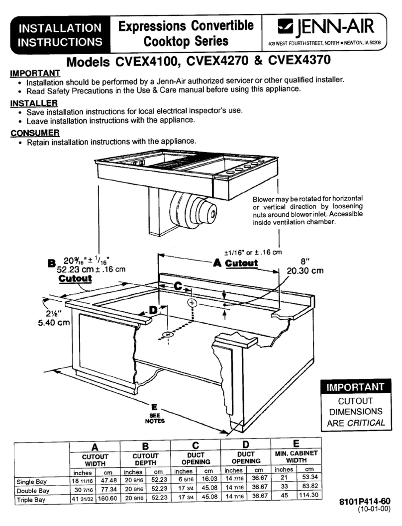
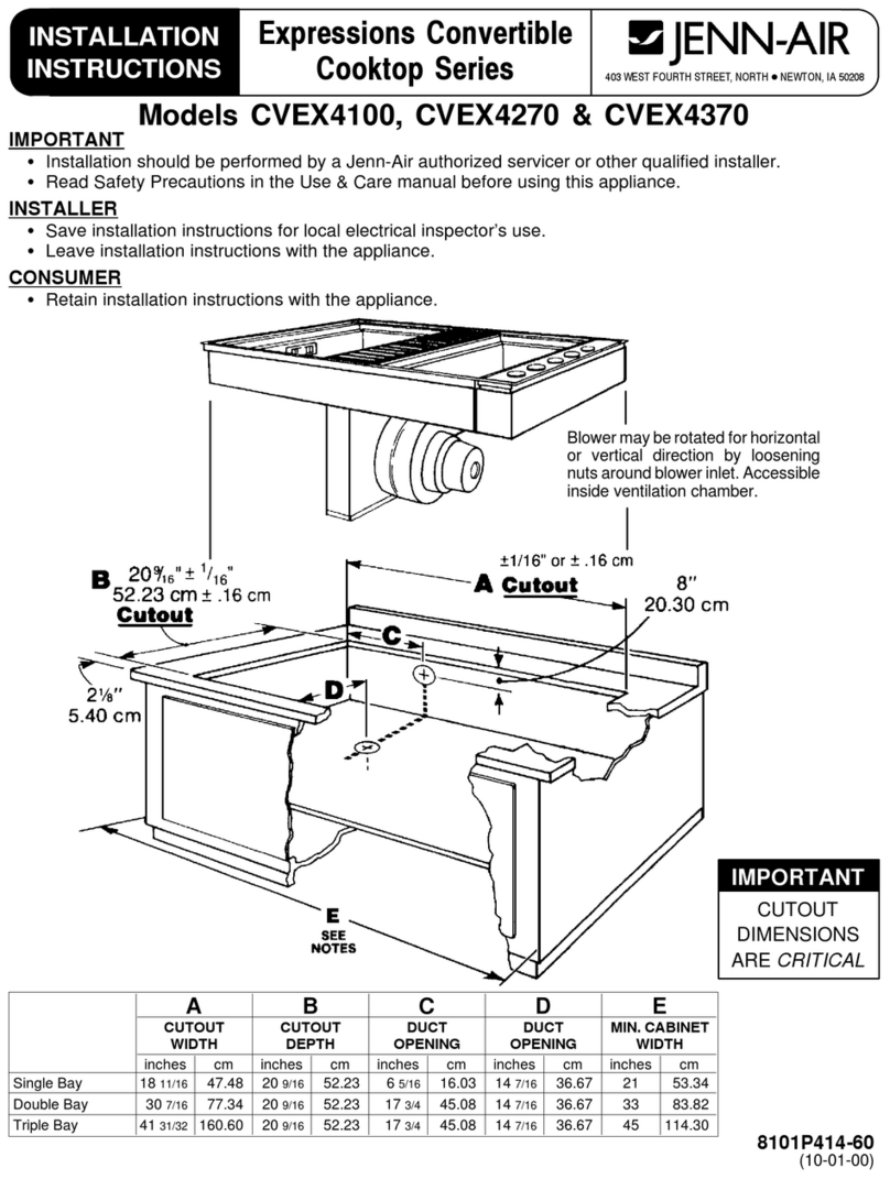
The CountertopCutout,Cabinet FrontCutout and DuctOpening oftheapp lance shall be conducted by the installer a_
shouldbe preparedaccordingtothe Illustrationon page1 and 2. ing to the instructions given. -;
Installthe LowerControlPanel in the bottomoftheCabinet
Cutoutas shownusingscrewsfrom Hardwarepack. (Fig.l) Installa manualshutoffvalve inan accessiblelocationin,tl_:g_,
ne extema to ths appliancefor the purpose ofturning on!.or_
TopV_, LOWtRco_rmoLP_eL shuttingoffgas tothe appliance. :
Make the gas connectionto the inletofthe apptiance p_
regulatoron this appliancewith a ½" malepipe thread, Us_;
approvedpipejointcompoundresstanttothe actionofLP gas_!i
pipe connections.Test all joints for gas leaks with a
watersolutionorotheracceptedleakdetectionmeans_
forgas eaksw th an openflame . ::.. __ :-.:y_:'_:t_t
Fig.1ii
Positionunitin the CountertopCutout.Main ControlPanel should
overlaptop ofLowerControlPanelas shown.(Fig.2)
:!
