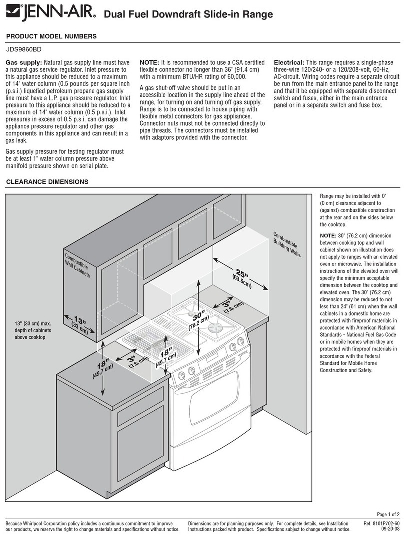
15. P.._onnectElectrical (Four Conductor Wire) (Figure 15)
•CAUTION: Make sure power to cable isOFF.
•Remove the range electrical service cover, located on the back, lower
left-hand corner.
• Remove the groun strap screw and bend the strap up as shown. Install a3/4"
(1.91 cm) cable clamp in the hole provided, below the terminal block.
• Strip 3" (7.62 cm) of outer insulation from the cable.
•Strip 1/2" (1.27 cm) of insulation from each wire.
•Pull the cable through the cable clamp.
•Make aloop inthe bare ground wire and attach ittothe range withthe screw
that held the ground strap.
° Attach the BLACK, RED, and WHITE wires (see #14.) Tighten the terminal
block nuts and the cable clamp.
•Tape the ground strap to the WHITE wire as shown. Install electrical cover.
16. Install Options (Figure 16)
• If the backsplash or side panels are to be used, install according to
instructions included in those accessories.
17. Position Range (Figure 17)
•Free-Standing. Adjust the range feet sothe range and cabinet height willbe
approximately the same. Slide the range into place, taking care not to
damage floor covering.
•Slide-In. Adjust range feet so that range top clears countertop. Slide/lift
range into place. Adjust feet so range is adjacent to countertop surface.
18. Anti-Tip Device Installation
NOTE: A risk of range tip over exists if the appliance is not installed in
accordance with the installation instructionsprovided. The proper use of these
devices minimizes the risk of TIP-OVER. In usingthese devices the consumer
must stillobserve safety precautions as stated inthe USE and CARE MANUAL
and avoid using the oven door and/or lowerdrawer as a step stool.
Instructionsare provided for installation in either awood or concrete floor. Any
othertype ofconstructionmay requirespecial installationtechniques as deemed
necessary to provide adequate fastening of the ANTI-TIP bracket to the floor.
STEP 1 - Locating The Brackets
•Place the unit in itsfinal location.
•Remove the storage drawer or lower door panel (depending on model
being installed.)
•Mark the floor at the right and leftwhere the range front meets the floor.
NOTE: Protect the floor with masking tape prior to marking.
•Remove the range for access to the bracket mounting positions. Use
care to avoid damage to floor.
•Draw a lineon the floor at the back ofthe cutoutwhich isoffset23-5/16"
from the marks made at the front of the range (see illustration.)
•Locate the center (side to side) of the cutout. See illustration for
free-standing and slide-in dimensions.
•Positionbrackets 13-7/8" from center line and flush to the back line as
shown in the illustration.
•Use the bracket to mark holes for drilling. Proceed to STEP 2.
STEP 2- Installing The Brackets
•Wood Construction: Drill a 1/8" pilot hole in the center of each of the
marked holepositions(a nailorawl may be used ifa drillisnotavailable.)
Secure the ANTI-TIP brackets with the screws provided. Proceed to
STEP 3.
•Cement or Concrete Construction: Suitable screws for concrete
constructioncan be obtained at a hardware store. Drillthe requiredsize
hole for the screw obtained in the center of each of the marked hole
positions. Secure the ANTI-TIP brackets to the floor.
STEP 3- Range Installation
•Alignthe range to itsdesignated locationand slide itback intoposition.
Make sure that the rear levelingfeet are fully inserted intoand secured
by the ANTI-TIP brackets. NOTE: Leg levelers must be screwed out
1-1/2 turns.
BEND
(Figure 15)
(Figure 16)
(Figure 17)
A'TE,,AT_SC"E*"O'E,r _ooo7
rL_.EO.AW.A_ /
_._ \ REARor a_OUT
"_k BACK OF CUTOUT /
g
OF °
°°' /
_[7D.48 cm] "1 [59.21 ¢m]
FDRAV#_ LlNES AT
FRONT OF RANGE
"A" MIM *B"
30 1/8" t5 1116"
FRE£-STANDING (76.52 ¢m) (38.26 o_)
29 7/8 14 18116
SLIDE-IN (75.88 cm) (37.94 cm)
(Figure 18)
UEGt._I1B._RS

