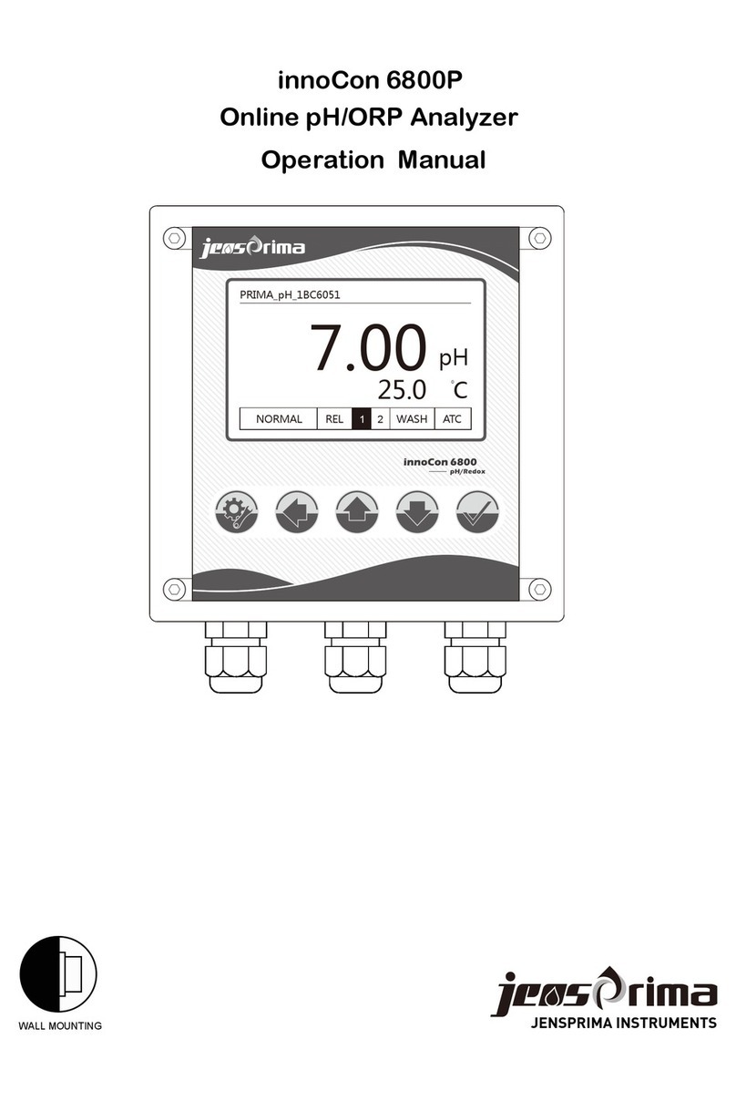
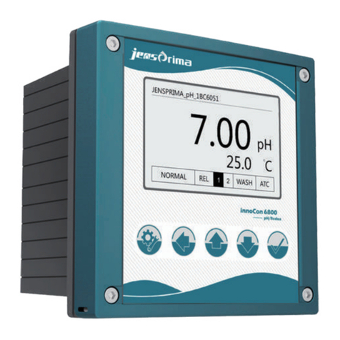
JensPrima innoCon 6501P User manual

WALL MOUNTING
innoCon 6501
CAL


innoCon 6501 Monitor Manual
www.jensprima.com
Contents
Safety 2
3
5
5
6
7
8
9
10
11
12
13
17
............................................................
Product Introduction....................................................
Installation
.................................................................
...................................................
Display
Electrical Connection
...................................................................
Configuration Mode...................................................
Calibration Mode .......................................................
Maintenance
.........................................................
P010 Temperature parameter setting
.................................
Controller Installation.................................................
Sensor Installation
....................................................
P020 Relay 1 parameter setting
.......................................
15
15
16
pH Calibration
.......................................................
ORP Calibration
.....................................................
P030 Relay 1 parameter setting
......................................
P040 Current output parameter setting
P050 Offset parameter setting
P060 Measurement parameter selection
P070 Factory Reset
.......................................
13
14
14
..............................
..............................
...................................................
Page 1

innoCon 6501 Monitor Manual
Page 2www.jensprima.com
Safety
Legal requirements
Sensor
Signs
√ This manual introduces all the risks that may arise during the use of this equipment,
√ Please make sure this manual is delivered to the third party along with innoCon 6501.
.
Please use sensors manufactured by JENSPRIMA; Damages to the instruments caused
by the use of sensors not manufactured by JENSPRIMA within the warranty period will
not be covered by the warranty.
Only technicians authorized by jensprima can modify and update the instrument.
of corresponding regions and countries.
This sign is used to instruct the operator.
!

innoCon 6501
CAL
innoCon 6501 Monitor Manual
Product Introduction
General Information
The innoCon 6501P economical controller is designed for online monitoring of water
treatment and industrial process, matching with innoSens pH / ORP electrodes for
measuring pH / redox potential and temperature in water. Pt 1000 automatic
temperature compensation, installation methods of panel/pipe way, standard with
one line of 4-20mA output and two lines of relay output.
Applicaitons
Sewage / wastewater treatment, environmental monitoring, industrial processes,
swimming pools etc.
Supply
1. innoCon 6501P Controller
2. Fixed bracket
3. Operation Manual
4. innoSens pH/ORP Sensor (Need to purchase separately)
Features
√The latest wide power input, economical, 4-20mA output
√Teflon terminal, super anti-interference ability
√Large-screen backlit LCD shows measured values, temperature and relay status
√Password protection, to prevent unauthorized operation
√Pt 1000 automatic temperature compensation function
√IP65 protection class, a variety of installation methods
√2 lines of High/ Low relay output
√One key to restore factory settings
www.jensprima.com Page 3

innoCon 6501 Monitor Manual
www.jensprima.com Page 4
±0.2 C
Technical Parameters
Parameters
Measurement range
Resolution
pH ORP Temperature
-10.0~120.0 C
-10.0~120.0 C
0~60.0C
-10~60.0 C
>10 Ω
12
°
°
°
°
°
-2000~2000mV-2.00~16.00pH
0.01pH
±0.01pH ±1mV
Pt 1000
1mV 0.1 C
°
Accuracy
Temp.Compensation
method
Temp.compensation
range
Ambient Temp.
Storage Temp.
Resistance input
Display
Isolated 4-20mA output, can set pH/ORP, max.500Ω
90-260VAC,50/60Hz;24VDC optional
IP65
90 x 90mm
96 x 96 x 140mm
innoSens 120 pH Sensor
Applicable to pH measuremnet of the general
water treatment and high pollution wastewater
innoSens 210 ORP Sensor
Applicable to ORP measuremnet of the general
water treatment and high pollution wastewater
innoSens 125 pH Sensor
Applicable to pH measurement of high
temperature and high pollution wastewater
such as pulp, electroplating, desulfurization
wastewater
innoSens 130 pH Sensor
Applicable to pH measurement of high temperature
sterilization, high temperature fermentation etc.
innoSens 145 pH Sensor
Applicable to pH measurement of pure water,
RO water and other low range conductivity water
innoSens 150 pH Sensor
Applicable to pH measurement of hydrofluoric acid water
0.5Kg
2 sets of ON/OFF contacts, independent setting of High
/Low alarm point, with hysteresis function; 5A/250VAC;
5A/30VDC
English/Chinese
Panel/Pipe
Backlit super large lattice LCD
Analog output
Language
Power supply
Protection class
Alarm output
Installation method
Dimension
Panel cut size
Weight
innoCon 6501P Controller Parameters:
innoSens pH/ORP Electrode:
Please refer to the
relevant technical
documents to select
the appropriate
electrode.

innoCon 6501 Monitor Manual
www.jensprima.com
Installation
The instrument can be panel mounted and pipe mounted.
Make a hole of 90 x 90mm on the instrument case, put the instrument into the case
from the front of the panel of the case, insert screws from the back cover, and then
lock the fastening block to the fastening bar from the back of the panel.
Panel Mounting
Dimension
Pipe Mounting
Page 5
Cut Size Bracket Used for Panel Mounting
Bracket
90mm
90mm
U-tube from Pipe Mounting
innoCon 6501
CAL
96mm
96mm
140mm

Installation of Sensor
JENSPRIMA has many types of industrial electrodes that have a specific connection
function. The most common installation methods are: immersion type, pipe type,
flow type, tank installation and live bolt assembly type electrode tube installation.
Note:The above-mentioned connecting parts must be tightened to prevent water from damaging the electrodes
Protection Cover Components and Installation
innoCon 6501 Monitor Manual
www.jensprima.com Page 6
innoSens 120 pH Electrode
pH 0~14, -5~70℃
Controller: innoCon 6800 & innoCon 6501
Sensor: innoSens pH/ORP Sensor
Flange type
Side wall
welding seat
Pipe type
Immersion type
Bypass type
Round junction box upper cover
innoSens 120 pH Electrode
pH 0~14, -5~70℃
El
O ring
O ring
Electrode protection tube
Protection cover
Molded shell electrode(3/4”thread)
Recommend to wrap the thread with tape
Glass electrode
Rubber seat
Fixed bracket
Water-proof cable connector
Round junction box lower ring
innoCon 6501
CAL

innoCon 6501 Monitor Manual
www.jensprima.com
Electrical Connection
Central axis connected
with cable Connect 90-260VAC
Ntework cable
conntected with cable
Relay 1
Probe connected with
temperature Relay 2
4-20mA Output
The connectors of the controller are located behind the instrument cover,
only trained personnel can open the cover for wiring power, relay and signal
outputs. Use a screwdriver to unscrew the four screws on the back cover for
electrical connection.
Terminals
Page 7
Extension of electrical wire:
When opening the wire, make sure
to remove the black conductive rubber
cover outside the central axis.
Network
Cable
Central
Axis
mA-
mA+
Pt1000
4-20mA: Isolation Max. Load 600 ohm
Relay: 5A/250VAC 5A/30VDC
pH/ORP
Ref
Relay2
Relay1
90-260VAC
50/60Hz
!
90-260VAC
50/60Hz
!Relay1
Relay2
Pt1000
pH/ORP
Ref
mA-
mA+
Danger:
Electrical connections must be
carried out by technicians who
got special trainings.
Note:
Power supply must be cut off
prior to any connection, otherwise
the instrument and the sensor are
likely to be damaged.

innoCon 6501 Monitor Manual
www.jensprima.com
Display
Front View of the Controller
Relay Indicate
Unit
Temperature
Secondary display area
Main
display
area
Calibration
ATC -- Temperature
compensation mode
ATC ( Auto)/MTC (Manual )
Button Functions:
Menu/Back
Key
Calibration
Key
Enter
Key
Arrows
Key
Under measurement interface, press and
hold this button for 3 seconds to enter the
setup menu and return to the previous menu.
Under measurement interface, press and
hold this button for 3 seconds to enter the
calibration menu
Accept input value or selected menu
Under measurement interface, press this key
Press this button to switch the display backlight
Browse menus, change settings, and input
value,under measurement interface
Press this button to switch measurement
value and current
Enter the setting mode with password 0011.
Any time press can exit the calibration mode or go back to the previous
menu. Press same key to the measuring mode.
Page 8
Current Indicate
innoCon 6501
CAL
CAL

innoCon 6501 Monitor Manual
www.jensprima.com
Under measurement menu,press and hold
Passord Setting
Ralay 1 parameters setting
Offset parameters setting Measuremen
Selection
t Parameter Restore factory reset
Relay 2 parameters setting Current output parameters
setting
Temperature parameters
setting
Press input correct
password: 0011
key to enter password interface(The
backlight is automatically lit at this time.)
Press Enter key (If there is no button operation within 3 minutes, it will automatically
return to the measurement interface.)
Page 9
1
Press input password: 0011, then press enter setting menu,
When incorrect password is input, it will automatically leave and return to
measurement mode.
Any time press can exit the calibration mode or go back to the previous
, you can also back to the measurement mode by pressing same key.

Automatic temperature measurement offset correction: range ±10.0
°C, Press key and select, press key to store and
enter the next setting, press key to select not to store and exit
the parameter setting.
innoCon 6501 Monitor Manual
www.jensprima.com
P010 Temperature Parameters Seng
Page 10
Temperature parameter setting main screen, press enter P011
, press exit parameter setting.
。
Measurement setting of temperature by manual.When the instrument
is not connected to the temperature sensor, under the measurement
mode, the instrument will use this temperature as the temperature of
the liquid to be tested, the setting range is -10.0~+120.0°C. Press
key to select, Press to store and enter the next
setting, Press key to choose not to store and exit the parameter
setting.
Calibration setting of temperature by manual: When the instrument is
not connected to the temperature sensor, under the calibration mode,
the instrument will use this temperature as the calibration temperature,
the setting range is: 0.0~60.0 ° C. Press key to select,
Press key to store and enter the next setting, Press key to
choose not to store and exit the parameter setting.
Damping coefficient setting: setting range: 0~50. Press
key to select, Press key to store and enter the next setting,
Press key to choose not to store and exit the parameter
setting.

innoCon 6501 Monitor Manual
www.jensprima. com
Parameter Seng of P020 Relay 1
Page 11
Main screen of Relay 1 Parameter setting:Press key to enter
the P021, press key to exit the parameter setting.
Switch selection of Relay 1: Press key to select the relay
to open or shut down. Press key to store and enter the next
setting. Press key to choose not to store and exit the parameter
setting.
Action mode selection of Relay 1: Press and Select relay
is high action or low action. Press to store and enter the next
setting, press key to choose not to store and exit the parameter
setting.
Operating point setting of Relay 1: Press key to select the
action of the relay. Press to store and enter the next setting,
press key to choose not to store and exit the parameter setting.
Hysteresis setting of Relay 1: Press key to select the
hysteresis amount of the relay. Press key to store and enter
the next setting, Press key to choose not to store and exit
the parameter setting.

innoCon 6501 Monitor Manual
www.jensprima.com
Parameter seng of P030 Relay 2
Page 12
Main screen of Relay 2 parameter setting: Press key to enter
P031. Press key to exit the parameter setting.
Switch selection of Relay 2: Press key to select the relay
to open or shut down. Press key to store and enter the next
setting. Press key to choose not to store and exit the
parameter setting.
Action mode selection of Relay 1: Press and select the
relay is high action or low action. Press to store and enter the
next setting. Press key to choose not to store and exit the
parameter setting.
Operating point setting of Relay 2: Press key to select
the action point of the relay, pH: -2.00~16.00 / ORP: -2000~+2000.
Press to store and enter the next setting. Press key to
choose not to store and exit the parameter setting.
Hysteresis setting of Relay 2: Press key to Select the
hysteresis amount of the relay. Press to store and enter next
setting. Press key to choose not to store and exit the
parameter setting.

innoCon 6501 Monitor Manual
www.jensprima.com
Parameter seng of P040 current output
Parameter seng of P050 offset
Page 13
Main screen of pH measuring current setting: Press key to
enter P041. Press key to exit the parameter setting.
Corresponding value setting of 4mA output: Press key
to select, range is -2.00~15.00,-2000~+1900mV. Press key to
store and enter the next setting. Press key to choose not to
store and exit the parameter setting.
Corresponding value setting of 20mA output: Press key
to select, range is pH:-1.00~16.00,-1900~+2000mV. Press
key to store and enter the next setting. Press key to choose
not to store and exit the parameter setting.
Main screen of pH offset setting: Press key enter P051. Press
key exit the parameter setting.
Press the key and select, range:±2.00pH. Press
key to store and enter the next setting. Press key to choose
not to store and exit the parameter setting.

innoCon 6501 Monitor Manual
www.jensprima.com
Measurement parameter setting of P060
P070 restore factory setting
Page 14
Main screen of pH/ORP measurement selection: Press key
and enter P061, press key and exit the parameter setting.
Press key and select. Press to store and enter the
next setting. Press key to choose not to store and exit the
parameter setting.
If you select the pH mode in P091, then need to select the sensor
type in P092, there are glass sensor(GLSS) and antimony sensor
(Anti). Press key and select. Press key to store and
enter the next setting. Press key to choose not to store and
exit the parameter setting.
Main screen of restore factory setting: Press key and enter
P071. Press key and exit the parameter setting.
P
execute and exit. Press key to choose not to execute and exit
the parameter setting
ress key and select YES or NO. Press key to

Under the measurement interface, press key and hold the calibration button CAL for 3
seconds to enter the calibration mode, the backlight will automatically light up.
CAL
innoCon 6501 Monitor Manual
Calibration Mode
Page 15www.jensprima.com
Note: Wash and dry the sensor before adding each standard solution.
Enter Calibration Mode
pH Calibration
1
After the two-point calibration is completed, the percentage of the slope
of the calibrated electrode is displayed. It is recommended to replace the
electrode when it is lower than 80%. Press the key to return to the
measurement mode.
The screen shows the percentage of the slope after the last
calibration. Press key to enter the next screen, press
key to leave the calibration mode.
Display the first standard solution value (buffer 1), press
button to select 7.00 or 6.86, the next time you enter, the last option
will be automatically remembered, press key to enter the
automatic calibration, the calibration icon in the lower left corner of
the screen will flash, the reading value will be automatically locked,
and it will automatically enter the next screen after locking, press
key to leave the calibration mode.
Press key to select the 2nd standard solution value
(buffer 2), The last option will be automatically remembered when you
enter next time, press key to enter the automatic calibration, the
calibration icon in the lower left corner of the screen will flash, the
reading will be automatically locked. After locking, it will automatically
enter the next screen and press key to leave the calibration
mode.
flash aut
rocess.

In the ORP measurement mode, clean the electrode and put it into the ORP standard
solution. Press the key to change the value of the secondary display area
(range: -300mV~+300mV) until the value of the main display above is same as the
ORP standard solution. Press to store and return to measurement mode, press
does not store and leaves calibration mode.
innoCon 6501 Monitor Manual
Page 16www.jensprima.com
ORP Calibraon
Less than the standard solution value Greater than the standard solution value
Error Indicaon
The calibraon icon will
flash automacally during
the calibraon process.
During calibration, when the value read by the electrode is not within the range of
the standard solution, when it is greater than the standard solution value, it shows Or.
When it is less than the standard solution value, it whows Ur. If it still cannot be
calibrated in 3 minutes (the reading value cannot be stabilized or is not in the range
of the standard solution), the calibration program will automatically jump out and
return to the measurement mode.

innoCon 6800 Monitor Manual
Page 16
Maintenance
Periodic electrode calibration
Periodic Calibration:Correct the above mentioned two kinds of errors , to ensure accurate
measurement;
Calibration cycle: calibration requirements are different based on different applications.
Recommend to calibrate once between 7-15 days in general industrial
wastewater.
Calibration solution: Use a qualified buffer solution and ensure that the buffer solution does
not expire.
When PH / ORP electrode is used i n different conditions and environment, the reference
oozing interface will be polluted and blocked, or the surface of sensing glass film is
contaminated and covered, all these will lead to measurement error.
Periodic Cleaning of the electrode
It is recommended to periodically clean the electrode according to water quality at site,
remove the electrode from them edium, wipe with a clean wet tissue and rinse with
clean water. use a cleaning reagent to clean if the electrode is very dirty,
Regular cleaning :
Keep the exudation interface of the referen
ce electrode clean;
Keep the glass film clean.
Cleaning Cycle:Cleaning requirements are different based on different applications.
Recommend to clean once between 7-15 days in gener al industrial
wastewater.
Cleaning reagent : Clean wate r , 3 ~ 5% dilute hydrochloric acid, 3 ~ 5% NaOH and so on.
Periodic electrode maintenance
When the electrode is used in the strong acid, alkali or high temperature and other
applications, the ion balance of the glass membrane surface is changed, and will lead to
measurement drift or measurement error.
Regular maintenance:
Help to restore the electrode's ion balance and the precise temperature measurement;
Help to improve the electrode's life.
Maintenance cycle: usually sa
me as regular cleaning cycle.
Maintenance reagent: 3mol / L KCl solution
When the water is stopped for long time
Close the water sample
Turn off power supply;
Plug off the electrode cable and store the electrode in a special protective solution. Do not
store the electrode in a dry environment or place the electrode in purified water.
Store the glass electrode dow nin a not frozen indoor.
www.jensprima.com

JENSPRIMA INSTRUMENTS LIMITED
Web:www.jensprima.com
Email: [email protected]
© 2017 JENSPRIMA INSTRUMENTS, all rights reserved
Table of contents
Other JensPrima Measuring Instrument manuals