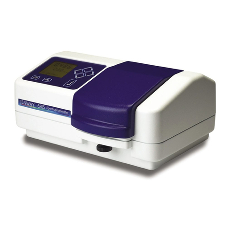
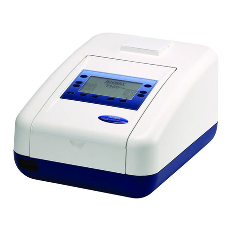
jenway 6405 User manual

MODELS 6400/6405
SPECTROPHOTOMETERS
OPERATING MANUAL
640 050/REV B/11-99

MODELS 6400/6405
SPECTROPHOTOMETERS
OPERATING MANUAL
CONTENTS
SAFETY
SECTION 1 INTRODUCTION
Instrument Description 1.1
Instrument Specification 1.2
SECTION 2 INSTALLATION
Unpacking 2.1
Installation 2.2
Controls 2.3
Inputs/Outputs 2.4
SECTION 3 OPERATION
Operating Overview 3.1
Instrument Set-up Menu 3.2
Photometrics 3.3
Spectrum Mode 3.4
Multi-Wavelength Mode 3.5
Kinetics Mode 3.6
Quantitation Mode 3.7
Good Practice Guidelines 3.8
SECTION 4 MAINTENANCE
General 4.1
Tungsten Halogen Lamp Replacement 4.2
Deuterium Lamp Replacement 4.3
SECTION 5 ACCESSORIES
Accessories 5.1
Spares 5.2
SECTION 6 INTERFACING
Serial Interface 6.1
RS232 6.2
Recorder Output 6.3
SECTION 7 EXAMPLE PRINTOUTS
Photometrics Mode 7.1
Spectrum Mode 7.2
Multi-Wavelength Mode 7.3
Kinetics Mode 7.4
Quantitation Mode 7.5
640 050/REV B/11-99

SECTION 8 WARNING AND ERROR MESSAGES
Messages relating to Power On Self Test a)
Photmetrics, Spectrum, Multi-Wavelength,
Kinetics and Quantitation Modes b)
Photometrics Mode c)
Spectrum Mode d)
Multi-Wavelength Mode (please refer to a) e)
Kinetics Mode f)
Quantitation Mode g)
Accessories h)
EC Declaration of Conformity
640 050/REV B/11-99

SAFETY
Please read this information carefully prior to installing or using this equipment.
1. The units described in this manual are designed to be operated only by trained personnel. Any
adjustments, maintenance or repair must be carried out as defined in this manual by a person
qualified to be aware of the hazards involved.
2. It is essential that both operating and service personnel employ a safe system of work in
addition to the detailed instructions specified in this manual.
3. The covers on the units should only be removed by personnel who have been trained to avoid
the risk of shock.
4. References should always be made to the Health & Safety data supplied with any of the chemicals
used. Generally accepted laboratory procedures for the safe handling of chemicals should be
employed.
5. If it is suspected that safety protection has been impaired in any way, the unit must be made
inoperative and secured against any intended operation. The fault condition should be
immediately reported to the appropriate servicing authority.
640 050/REV B/11-99

SECTION 1
INTRODUCTION
1.1 INSTRUMENT DESCRIPTION
The Models 6400 and 6405 incorporate a wide range of features designed to satisfy the needs of users
seeking to maximise the efficiency of routine and specialised UV and Visible spectroscopy tasks.
Menu based operation guides the user through all the available modes and ensures that unfamiliar
operators are able to complete satisfactory analyses. Multi-language capability allows screen instructions
to be presented in a choice of English, French, German, Italian, Spanish, Swedish or Portuguese.
The 6400 and 6405 spectrophotometers incorporate an innovative optical system which reduces stray
light and enhances overall reliability by minimising the number of optical elements employed. The
sample chamber allows total sample presentation flexibility with cells from 100mm path length down
to micro-sample capacity being readily accommodated. Eight position motor driven multi-cell changer
and sipper pump accessories are available, either factory fitted or as user installable options. In addition,
an electronically temperature controlled Peltier cell holder is available for situations where a constant
temperature is essential.
A scanning facility is provided on both the 6400 and 6405. The scan range, speed and resolution can
be user adjusted and the resultant scan, which appears in real time on the graphics display, can be auto
scaled to give enhanced visibility. Peaks and valleys are labelled with wavelength and absorbance
values and can be readily down loaded to the optional internal printer or, via the serial interface, to a
PC. A cursor facility allows the user to interrogate specific parts of the scanned data.
Full kinetics capability is incorporated into each unit and allows, usually in conjunction with the
Peltier cell block, full analysis of timed reactions.
Methods producing non-linear results can also be accommodated by using powerful in-built software
in conjunction with the multi-cell changer. Up to seven data points can be determined automatically
and used to construct a curve. A variety of statistical methods are available to ensure a close correlation
to all curve shapes.
Design of the units is such that minimal routine maintenance will be necessary in normal use.
This manual has been produced to help guide you through the many operating modes and features
available on the 6400 and 6405. Our hope is that operation of the units is such that reference to this
manual will be required only rarely. It is our aim to ensure that all information needed to operate these
products satisfactorily is contained within. If, however, you experience any difficulties please contact
the manufacturer or your local distributor for guidance.
640 050/REV B/11-99
1

1.2 INSTRUMENT SPECIFICATIONS
Transmittance
Range: 0 to 199.9%T
Resolution: 0.1%T
Accuracy: ±0.1% @ 10%T
Stray Light: <0.05% @ 340nm
Absorbance
Range: -0.300 to 3.000A
Resolution: 0.001A
Photometric Accuracy: ±0.005Abs @ 1.0Abs
Drift: <±0.001Abs/hour after 15 minute warm up
Concentration
Range: -300 to 9999 (resolution dependant)
Resolution: 0.001/0.01/0.1/1
Units: ppm, mg/l-1, g/l-1, M, %, blank
Factor: 0.000 to 9999.99
Wavelength
Range: 320 to 1100nm (6400) 190 to 1100nm (6405)
Resolution: 0.1nm
Accuracy: ±1.0nm
Bandwidth: 5nm
Maximum Scan Speed: 1400nm/min
Readout: 240x128 pixel reflective LCD
Outputs: Analogue / RS232 serial port
Light Source: Tungsten Halogen (6400/6405)
Deuterium (6405)
Input Voltage: 115Va.c. / 230Va.c. ±20%
Input Power: 100VA (6400) 200VA (6405)
Size: 520 x 330 x 180mm
Weight: 15Kg
640 050/REV B/11-99
2

SECTION 2
INSTALLATION
2.1 UNPACKING
Remove the Model 6400/6405 from the packaging and ensure the following items are present:
1. Model 6400 / 6405 Spectrophotometer
2. Mains cable
3. Pack 100 disposable cuvettes
4. Optional accessories (as ordered)
Any shortages or damage should be reported immediately to the manufacturer or your local
distributor.
2.2 INSTALLATION
The 6400 / 6405 are designed to operate on 230V or 115V (50/60Hz) mains supply.
The standard 2 metre cable supplied with the unit is fitted with an IEC type connector which can be
plugged directly into the POWER IN socket on the rear panel.
The mains fuse is housed within the POWER IN socket. When replacing the fuse the unit should be
disconnected from the mains supply.
In the event of the fuse failing after replacement, it is advisable to consult with the manufacturer or
your local distributor before proceeding further.
Fuse rating: 1.6A (T-type) for 230V operation
3.15A (T-type) for 115V operation
NOTE: The unit should be positioned within 1.5 metres of an earthed mains supply.
VOLTAGE SELECT
NOTE: When changing the voltage select switch position always ensure the fuse rating is
correct.
Before attempting to change the voltage select, disconnect the unit from the mains supply. Withdraw
the fuse holder from the power input socket and remove the fuse. Extract the grey fuse retainer and
rotate so that the correct voltage is visible through the aperture in the fuse holder. Replace the fuse
retainer in its holder, fit the correct fuse and push the assembly back into the power input socket.
MAINS CONNECTIONS
The unit may have been supplied with a moulded connector suited for use with your local supply
outlet. If, however, it has been supplied without a plug fitted, a suitable plug for your local supply
should be wired as follows:
The wires are colour coded to conform to the internationally recognised standard such that:
BROWN LIVE
BLUE NEUTRAL
GREEN/YELLOW EARTH
IMPORTANT: THE UNIT MUST BE EARTHED
The green/yellow wire in the a.c. supply must be connected to a properly grounded terminal.
640 050/REV B/11-99
3

2.3 CONTROLS
Print key - Provides a mode dependent printout - refer Section 7 for examples.
Cal key - performs a photometric calibration at the current wavelength.
Goto key - used to set wavelength.
used to select the displayed menu option and for entering values.
used to move horizontally and vertically between menu options. Up and down
arrow keys are also used to select non-numeric set up parameters.
Icons
The following icons may appear on the instrument display during operation.
UV lamp on (6405 only)
This icon will flash during pre-strike warm up.
Tungsten Halogen lamp alight. If the lamp(s) fail the symbol will
not be shown.
Current cell holder position in multi-cell holder (0 - 7).
0 = position 0 which is the default for blank.
Recalled scan in Spectrum mode or calibration curve in Quantitation
mode.
640 050/REV B/11-99
4

2.4 INPUTS / OUTPUTS
Fig. 2.4.1 Rear Panel Layout
1. LAMP ACCESS PANEL This panel allows the user to gain access to the lamps
when replacement is necessary.
NOTE: The lamp access panel and all ventilation slots must not be covered or obstructed
at any time.
2. Aux. SOCKET 7 pin DIN socket. Serial communications port for the
auxilliary peltier control unit.
3. Analog SOCKETS 2 x 4mm pin sockets for analogue output.
4. RS232 SOCKET 25 way output socket for RS232.
5. ROCKER SWITCH On/Off switch for the unit.
6. POWER IN SOCKET IEC type connection socket for mains cable.
7. FUSE HOLDER Fuse ratings - 1.6A T-type for 230V
3.15A T-type for 115V
640 050/REV B/11-99
5

SECTION 3
OPERATION
3.1 OPERATING OVERVIEW
This section has been provided as an overview of the product functions. For specific instructions on
each mode of operation please refer to the appropriate section as detailed in the Contents section at the
front of this manual.
Power On Systems Test
These test the instrument’s memory and lamp. Wavelength calibration is also performed by finding
the peak transmittance at 0nm. An initial baseline is also acquired.
A failure will be be shown by a X appearing in the box to the side of the parameter under test, together
with an error message.
(Refer to Section 8 Warning and Error Messages for explanatory notes and action)
Operating Mode Menu
Photometrics
This is the basic measurement mode that displays transmittance, absorbance or concentration at a
single wavelength.
Calibration is performed using the Cal key.
Wavelength is set using the Goto key or the up and down arrow keys.
Concentration is calculated from absorbance multiplied by a factor plus a user entered offset. Readings
can be printed to the in-built printer or serial port.
640 050/REV B/11-996

Spectrum
This mode allows samples to be scanned between two user set wavelengths at 5nm, 1nm or 0.2nm
intervals. The highest scan rate is attained by scanning at 5nm intervals.
Scan statistics which list peaks and valleys can be displayed.
An optional peak and valley filter can be employed which only lists peaks and valleys that exceed a
percentage of the difference between the maximum peak and the minimum valley.
A movable cursor (left and right arrow keys) can be used to take readings directly from the scan in
increments of the scan interval.
The scan axis can be automatically re-scaled on completion of a scan.
Two scans can be stored.
A baseline can be manually acquired.
The instrument can be set to repeat a scan at a user set interval for a user set number of times.
The instrument can be set to print out on completion of an auto-repeat scan.
Printed information includes the scan parameters and the statistical information. The in-built printer
allows graphical printout of the spectrum. Spectrum data points are printed over the serial port.
Multi Wavelength
This mode allows transmittance or absorbance measurement at two user set wavelengths. Difference
and ratio of the two readings are also displayed.
The user initiates a measurement at the two wavelengths by selecting the sample menu option.
Calibration is also performed automatically at the two wavelengths.
640 050/REV B/11-99
7

Kinetics
This mode allows kinetics rate measurements to be made. Absorbance or transmittance versus time is
displayed graphically.
The user can enter the kinetics lag time and run time.
Alternatively, the kinetics run time can be set to commence when the absorbance or transmittance
exceeds or falls below a user set level.
The kinetics factor can be set by the user.
The graphical axis can be set to automatically re-scale on completion of the kinetics run.
A line of best fit can be displayed. The line of best fit can be restricted to a user set portion of the
kinetics run.
Post-kinetics statistics, which includes the initial absorbance or transmittance level, the change in
absorbance or transmittance, the kinetics value and the equation of the line of best fit (y=mx + c).
The in-built printer allows graphical printout of the kinetics run.
Quantitation
This mode is only available when the instrument is fitted with a multi-position cell holder.
This mode allows a calibration curve of absorbance or transmittance versus concentration to be
constructed.
Sample concentrations are displayed using the relationship of concentration versus absorbance or
transmittance derived from the calibration curve. The calibration curve is displayed graphically.
The multi-position cell holder forms an integral part in the operation of quantitation mode. Two to
seven calibration standards are loaded into the cell holder in positions 1 to 7. The user enters the
number of calibration standards used and their concentrations (using the cell holder to identify each
standard). Cell holder position 0 is reserved for zero absorbance calibration or for subsequent sample
measurement.
The curve fit employed for constructing the calibration curve can be selected between linear interpolation
(straight lines between calibration points), linear regression (line of best fit) or linear regression through
zero (line of best fit that passes through point 0,0).
The concentration graph axis can be automatically recalled on completion of a calibration. Two
calibration curves can be stored, together with the calibration standards used to construct the curve.
640 050/REV B/11-998

3.2 INSTRUMENT SET-UP MENU
Language
Allows selection of the instrument operating language.
Instrument ID Number
Allows entry of a value between 1 and 999999 that appears on all printouts. This can be used to
provide identification of the instrument.
Printer Form Feed
Advances paper in the in-built printer by four lines. Used when fitting a new paper roll.
Clock...
Allows access to the clock set-up menu.
Time
Allows entry of the time (24 hour clock).
DateFormat
Allows selection between European date format (day/month/year) or American date format (month/
day/year). The selected format is applicable to all displayed dates.
Date
Allows entry of the date (in the selected format).
Display
Allows choice of time, date or neither display in measuring modes.
640 050/REV B/11-99
9

UV Lamp Save...
Allows access to the UV lamp save menu.
Enable
Turns the lamp save feature on or off. When on, the deuterium lamp will only be switched on when the
wavelength (or scan range in spectrum mode) falls below the wavelength set in this menu. When off,
the deuterium lamp is permanently on.
Wavelength
The wavelength below which the UV lamp will be switched on. This is only used if the UV lamp save
feature is enabled.
ContrastAdjustment...
Allows adjustment of the display contrast. The left and right arrow keys can also be used for contrast
adjustment when the instrument is in the operating mode menu.
640 050/REV B/11-99
10

3.3 PHOTOMETRICS MODE
Having selected the Photometrics Mode from the Main Menu options the following display will be
shown:
It is recommended that set-up parameters be reviewed prior to calibration or measurement to ensure
the selected measurement mode and values are correct.
Select SET UP mode using the key and press
MEASURE MODE
Select %Transmittance, Absorbance or Concentration -
CONCENTRATION SETUP...
CalStandard
Allows entry of the calibration standard that is calibrated to by pressing the Cal key when the measure
mode is set to Concentration. Absorbance is calibrated to this standard by calculating the multiplication
factor that produces the calibration standard concentration.
Factor
Allows direct entry of the absorbance multiplication factor for concentration measurement mode.
640 050/REV B/11-9911

Offset
Allows the zero absorbance concentration to be offset by the value entered. The offset is set to zero by
calibration to a standard.
Resolution
The maximum resolution that concentration readings are displayed to can be set up to three decimal
places. The instrument will automatically display concentration readings to the maximum possible
resolution using this parameter. For example, a concentration value of 1 can be displayed as 1, 1.0,
1.00 or 1.000, depending on the resolution set. This parameter does not affect the measuring range for
concentration: a concentration value of 1999 will be displayed as 1999, regardless of the resolution
setting.
Units
Allows selection of the displayed concentration units.
Each parameter can then be set using the keys and pressing to confirm value entered.
To exit the CONCENTRATION MENU use the key and then press to return to the main
set up options.
To select the INSTRUMENT SET UP MENU ... use the key and press . The instrument
will enter the menu.
For details on setting up these parameters refer Section 3.2. .
NOTE: ACCESSORY SET UP... will only be displayed if an accessory is fitted to the
instrument.
Preparing to Make a Measurement
Select the required wavelength using the up/down keys, or by pressing the Goto key and entering
the required value using the numeric keypad. Press to confirm.
Open the sample chamber lid and place a blank sample in position. Close the sample chamber lid
and press the Cal key. The display will momentarily show - Calibrating Dark Level and then
Calibrating Light Level. The display will then update to show 100.0%T or 0.000Abs, depending on
mode selected. Remove the blank sample from the sample chamber.
The instrument is now ready to perform a measurement.
Place the unknown sample into the sample chamber and close the lid. The instrument display will
show the sample value directly as %T or Absorbance, as appropriate.
640 050/REV B/11-99
12

3.4 SPECTRUM MODE
Having selected the Spectrum Mode from the Main Menu options the following display will be shown:
Spectrum Mode Pre-Scan Menu
A blank graph is displayed, using the current settings for measurement mode, the y-axis range and the
scan wavelength range.
Mode
Takes the instrument back to the operating mode menu.
Set-up
Allows access to the spectrum mode set-up menu and instrument set-up menu.
Scan
Executes a scan between the current start and end wavelengths at the scan interval. Zero transmittance
is calibrated prior to starting the scan. The scan can be paused and continued, or can be aborted.
Recall
Allows a previously saved scan to be recalled onto the display. The time and date at which the scan
was saved are momentarily displayed. Recalling a scan does not change the next scan set-up parameters.
Up to two saved scans can be recalled, plus a current scan if one has been performed (current scan data
is lost if the operating mode is changed, or if the instrument is switched off).
Baseline
Acquires a new baseline over the operating wavelength range for the instrument.
It is recommended that set-up parameters be reviewed prior to calibration or measurement to ensure
the selected measurement mode and values are correct.
Select SET UP mode using the key and press
640 050/REV B/11-99
13

Set Up Menu
Each parameter can then be set using the keys and pressing to confirm value entered.
Measure Mode
Selects between transmittance or absorbance for the scan y-axis.
StartWavelength
The wavelength at which the scan will commence.
EndWavelength
The wavelength at which the scan will finish.
ScanInterval
The wavelength interval at which the instrument will scan.
Storing Warning Messages
When a scan is saved with two scans already saved, the instrument prompts to confirm the new scan
save since the oldest saved scan will be overwritten. This message can be suppressed by setting the
storing warning messages to off. With the storing messages off, a scan save will automatically overwrite
the oldest previously saved scan with no further user intervention.
Record Range...
Allows access to the spectrum record range menu option which allows the y-axis range to be set.
Y-Axis Max
The highest absorbance or transmittance (depending on the measurement mode) that is displayed on
the scan axis.
Y-Axis Min
The lowest absorbance or transmittance (depending on the measurement mode) that is displayed on
the scan axis.
640 050/REV B/11-99
14

NoiseFilter
The post-scan statistical feature will list all turning points (peaks and valleys) when the noise filter is
set to off. If the noise filter is set to fine, medium or coarse then peaks and valleys which deviate from
the preceding peak or valley by a percentage of the total excursion of the scan (the difference between
the highest peak and the lowest valley) are omitted from the statistcal peaks and valleys tables. More
peaks and valleys will be omitted if the noise filter is set to coarse (only those peaks and valleys which
exceed 10% of the total excursion) than for medium (5%) or fine (1%) settings.
AutoRe-Scale
This feature can be turned on or off. When auto re-scale is on, the instrument will automatically
change the Y-Axis minimum and maximum points to display the scan to it’s greatest resolution. If set
to off, then the Y-Axis will use the user set maximum and minimum points.
Repeat Scan Time...
Allows access to the repeat scan set up menu, which allows the instrument to automatically repeat a
scan a number of times at a user set time interval.
AutoRepeatScan
Turns the automatic feature which repeats a scan at a user set time interval on or off.
Interval (Sec)
Allows entry of the time interval (in seconds) at which the instrument will repeat a scan when this
feature is turned on. The interval between scans begins upon completion of the first user initiated scan,
including the time to print the scan if the automatic print feature is turned on.
Repeat Scans
The number of times a scan will be repeated when the automatic repeat scan feature is turned on. This
does not include the first scan, which must be initiated by the user.
AutoPrint
If this option is turned on and the automatic repeat scan feature is turned on, then the instrument will
automatically print the scan (either to the in-built printer or to the serial port) upon completion of a
scan.
Instrument Set Up...
Allows access to the instrument set up menu.
For details of setting up these parameters refer Section 3.2.
Accessory Set Up...
This will only be displayed if an accessory is fitted to the instrument.
640 050/REV B/11-99
15

It is recommended that a new baseline scan is carried out prior to performing spectrum scans.
Select BASELINE from the menu options at the bottom of the display using the left arrow key and
then press . A baseline scan will now be executed.
Select SCAN from the menu options at the bottom of the display using the right arrow key.
Open the sample chamber lid and place the sample in position. Close the sample chamber lid.
Press SCAN and then the key to confirm. The instrument display will then show a blank graph
with the option to PAUSE or ABORT the scan.
On completion, the display will update to show the performed scan.
Performing a Scan
Spectrum Mode - Post Scan Menu
Once a scan has been performed or recalled, the following additional menu options are displayed.
Displayed < and > symbols indicate that further menu options are available and can be accessed using
the left and right arrow keys.
Save
Allows the displayed scan to be saved in non-volatile memory. A recalled scan cannot be saved. If
saving a scan will overwrite an already saved scan then a warning message will be displayed, requiring
a confirmation to overwrite the old scan. This message can be disabled, negating the need to confirm
the save scan option.
640 050/REV B/11-99
16
This manual suits for next models
1
Table of contents
Other jenway Measuring Instrument manuals
Popular Measuring Instrument manuals by other brands
SPECS
SPECS KolibriSensor user manual
Hanna Instruments
Hanna Instruments HI706 instruction manual
NUCLEONIX SYSTEMS PRIVATE LIMITED
NUCLEONIX SYSTEMS PRIVATE LIMITED GR612 instruction manual
Bruker BioSpin
Bruker BioSpin minispec mq60 user manual
HK Instruments
HK Instruments DPG Series installation instructions
Thermo Scientific
Thermo Scientific NanoDrop OneC user guide
