jenway 3345 User manual

MODEL 3345
ION METER
OPERATING MANUAL
547 009/REV A/08-99

MODEL 3345 ION METER MANUAL
SECTION 1 INTRODUCTION
Description 1.1
Specification 1.2
SECTION 2 INSTALLATION
Unpacking 2.1
Installation 2.2
Displays 2.3
Controls 2.4
Inputs/Outputs 2.5
SECTION 3 OPERATION
Menu Options 3.1
Common Menu Options 3.2
Using the unit with 2 sensors 3.3
Operating the unit with only one display 3.4
Endpoint detection 3.5
pH MODE
Setting up parameters 3.6
Entering pH Buffer Values 3.7
pH Calibration - Automatic 3.8
pH Calibration - Manual 3.9
Error Codes 3.10
Good Practice Guidelines 3.11
mV MODE
Setting up parameters 3.12
Temperature Measurement 3.13
ION ANALYSIS
Ion Selective Measurements 3.14
Good Practice Guidelines 3.15
Concentration Mode 3.16
Calibration 3.17
Entering Cal Buffer Values 3.18
Incremental Methods 3.19
Known Addition/Subtraction 3.20
Multiple Sample Addition/Subtraction 3.21
Operating the Instrument with Optional Stirrer 3.22
Datalogging 3.23
3345/REV A/08-99

SECTION 4 MAINTENANCE
General 4.1
Cleaning/Re-conditioning of Glass Electrodes 4.2
Ion Selective Electrodes 4.3
SECTION 5 OPTIONAL ACCESSORIES
SECTION 6 INTERFACING
GLOSSARY OF TERMS
3345/REV A/08-99

SECTION 1
INTRODUCTION
1.1 INSTRUMENT DESCRIPTION
The Model 3345 Ion Meter is a highly sophisticated product offering a host of valuable features, but retaining
simplicity of operation.
The structured menus allow easy access to features with single key strokes. On-line help is provided to
explain instrument functions and provide diagnostic information.
Important measurement features include the ability to operate both channels completely independently,
simultaneous display of readings and temperature on both channels, and independent indication of stable
readings. Details of the last calibration for each sensor are provided and all logged results and calibration
routines are date and time stamped, thus satisfying the requirements of Good Laboratory Practice (GLP)
quality assurance protocols.
The units will store up to 100 readings which can subsequently be recalled onto the instrument display or
downloaded to a printer or PC via the bi-directional RS232 link. User programmable options include the
ability to print out current readings or prompt calibration at pre-determined intervals and the setting of alarm
points which are activated when the measured parameters will fall outside the preset limits.
The Model 3345 offers additional flexibility with two additional modes of ion analysis - Known addition/
subtraction mode for the determination of ion concentration closer to the lower detection limit of the electrode,
and multiple Sample addition/subtraction allowing measurement in dense and concentrated matrices.
3345/REV A/08-99
1

1.2 INSTRUMENT SPECIFICATIONS
pH
Range -2 to 19.999pH
Resolution 0.1/0.01/0.001pH
Accuracy ±0.003pH
mV
Range -1999.9 to 1999.9mV
Resolution 0.1mV
Accuracy ±0.2mV
Concentration
Range 1 x 10⁻⁹ to 9.99 x 10⁹
Units Activity, ppm, %, mg/l, M or none
Resolution 3 significant digits
Accuracy ±0.003pX for monovalent ions
Input Impedance >1013Ohms
Number of Electrode Inputs 2
Temperature
Range -10 to 105°C / 14 to 221°F
Resolution 0.1°C / 1°F
Accuracy ±0.5°C / ±1°F
ATC Range 0 to 100°C / 32 to 212°F
Manual Temp. Comp. Range 0 to 100°C / 32 to 212°F
Number of Temperature Inputs 2
Auto Buffer Recognition 2, 4, 7, 9 and 10pH buffers with manual override facility
Pre-Programmed Ion NO3-, ION+, ION2+, ION-, ION2-, H+ , SCN-, Cu2+, S2-, CN-, I-, Br-,
Characteristics Cl-, Hg+2, Cd2+, Pb2+, F-, Ag+, CO3-, Ba2+, NO2-, ClO4-, NH4+, Ca2+,
K+
Calibration 1, 2 or 3 point pH / 1, 2, 3, 4 or 5 point Concentration
Outputs Analog 1mV per digit
Bi-directional RS232
Hi/Lo alarm outputs open collector 0.5A 50V max.
Datalogger 100 results
Clock 24 hour, hrs/min/sec or day of month, month and year/leap year
corrected
Alarm Points -2 to 19.999pH
±1999.9mV
1 x 10⁻⁹ to 9.99 x 10⁹
G.L.P. Calibration reminder with an interval of 1 to 999 hours from last
calibration Timed printout with an interval from 1 second to 1 day
Display LCD Graphics
Power Power Supply 9V a.c.
Size 275(l) x 240(w) x 150(d) mm
Weight 1.2Kg
3345/REV A/08-992

SECTION 2
INSTALLATION
2.1 UNPACKING
Remove the Model 3345 from the packaging and ensure the items within the package are as ordered.
Any shortages or damage should be reported immediately to the Manufacturer or your local
Distributor.
NOTE: Power Supply 021 033 is supplied with a moulded European plug. If this is not
correct for your local supply it should be cut off and a suitable local connector fitted
noting the colours of the internal conductors as follows:
Brown - Live Blue - Neutral
2.2 INSTALLATION
LCD CONTRAST
The LCD contrast can be set at any time. The LCD contrast potentiometer is accessible through the rear
panel adjacent to the power socket.
This adjustment should only need to be made on receipt of the instrument. After initial adjustment the instrument
will automatically adjust the contrast depending on the temperature of the glass.
For instruments supplied with the swing arm electrode holder the following assembly instructions should be
carried out:
1. Unpack the assembly and ensure the following items are present:
a) base block and b) swing arm. Assemble as illustrated. The moulded pivot is a tight push onto the pin.
2. Fit the pH electrode into the cut-out in the support block. The optional temperature probe, if supplied,
should be placed into the small hole in the centre of the block. The cable(s) should be passed through the
retaining clip on the holder and connected to the respective socket on the rear panel.
3345/REV A/08-993

SETTING LANGUAGE
Move to the SETUP menu using the arrow keys and press the key. Move the cursor to the INSTRUMENT
SETUP mode using the arrow key and press the key.Move the cursor to the LANGUAGE menu
and select the appropriate language by using the arrow keys. Once selected move to the EXIT option and
press the key. Pressing the key a second time will return the instrument to the measurement mode.
3345/REV A/08-99
4

2.3 DISPLAYS
1. PRIMARY DISPLAY -sensor 1 display currently selected as primary reading. Units
of measurement andcalibration point will also be shown at
the side of the main display.
2. TEMPERATURE DISPLAY - sensor 1 temperature display. Selected measurement unit and
MAN to indicate manual temperature will be shown at the
side of the display.
3. ENDPOINT SYMBOL -displayed once a stable reading is detected and is maintained
until the input changes.
4. ERROR MESSAGES -displays error messages for sensor 1.
5. MENU -used for selection of modes of operation. The selected
mode is reverse highlighted .
6. ICONS -used in pH and Ion modes to prompt steps of calibration and
sample measurement.
7. ERROR MESSAGES -displays error messages for sensor 2.
8. TEMP. DISPLAY -sensor 2 temperature display. Selected measurement unit and
MAN to indicate manual temperature will be shown at the
side of the display.
9. SECONDARY DISPLAY -sensor 2 display currently selected as secondary reading.
Units of measurement andcalibration point will also be shown
at the side of the main display.
10. REAL TIME CLOCK -giving continuous display of hours, minutes and seconds or
day, m onth and year. All logged results are automatically
time stamped.
3345/REV A/08-99
5

2.4 CONTROLS
Switches the instrument on and to standby.
Print key. Provides a printout of the current readings with an incremental sample number
depending on instrument operating mode. When pressed for the first time after a calibration,
the print out will give calibration information. The incremental sample number will be
reset after a calibration if auto cal print is set to on.
These keys are used to move around menus and for entering non-numerical functions.
Display select key. Used to toggle between primary and secondary displays.
Used to enter the exponential part of a value.
e.g. to enter 1.3 x 10⁻³ the key sequence is 1, ., 3, EXP, 3
Help key. Provides on-line help for menu options.
Used to select the displayed menu options and for entering parameters.
Used to change the sign of an entered number. It should be pressed after entering the
value. To enter a negative exponent this key should be pressed after entering the exponent
value - e.g. 1 x 10⁻³ - the key sequence is 1, EXP, 3, ±
Numeric keys 0 - 9 are used to enter numeric data for measurement parameters, calibration
data and limits.
3345/REV A/08-99
6
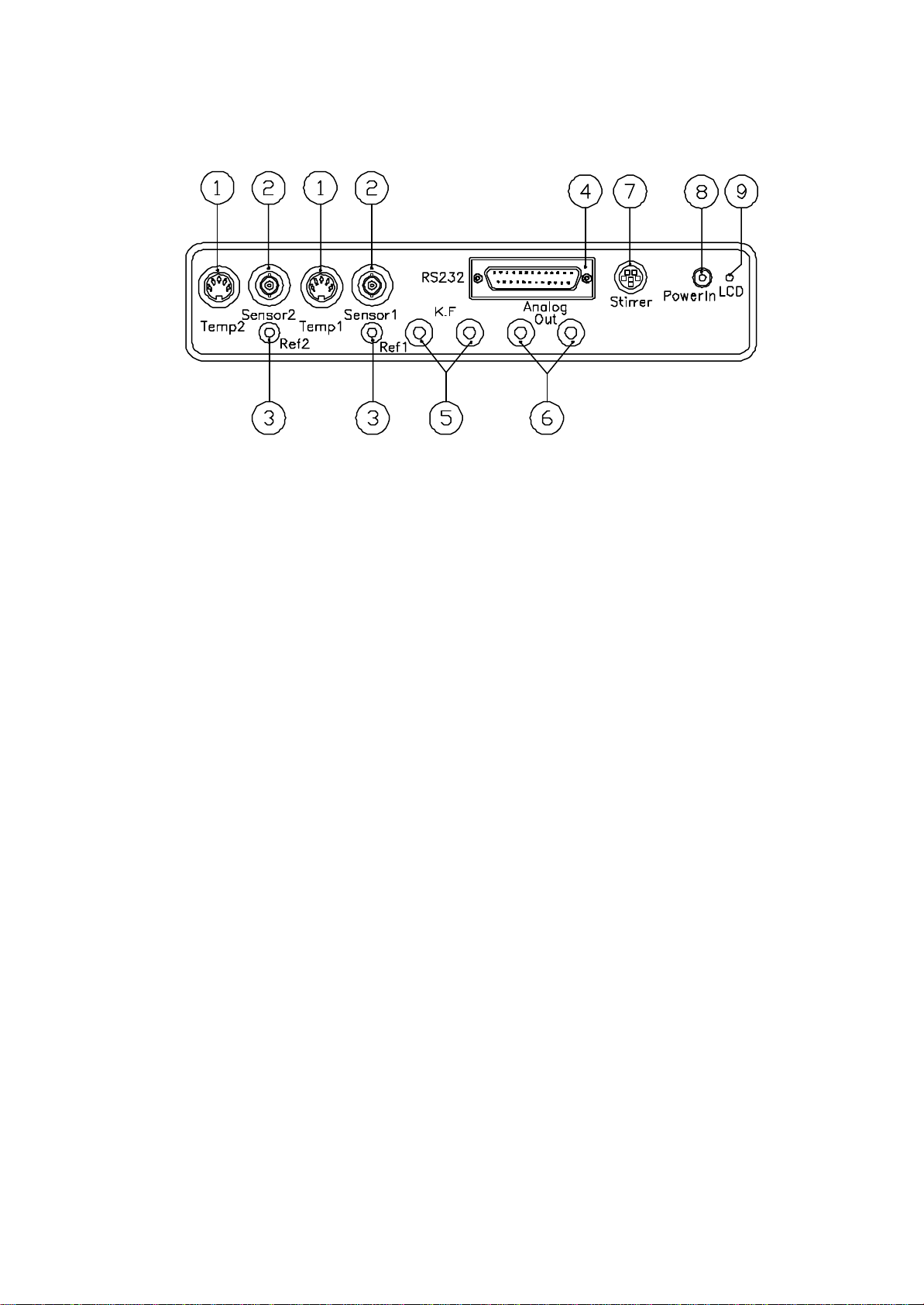
1. TEMP SOCKET 5 pin DIN socket for the automatic temperature compensation
(ATC) probe
2. pH SOCKET BNC connection socket
3. REF SOCKET 2mm pin connection socket for separate reference electrode
4. OUTPUT SOCKET 25 way D socket for RS232 and alarm connections
5. KARL FISCHER 2 x 4mm sockets. Polarised output. Karl Fischer titrations are
enabled by the provision of a 10µA polarising current output
6. ANALOG OUT 2 x 4mm sockets. Analog output proportional to primary
display reading
7. STIRRER Connection socket for optional stirrer
8. POWER IN 2.1 x 5.5mm socket allowing the power supply to be connected
to the unit
9. LCD LCD contrast potentiometer
2.5 INPUTS/OUTPUTS
3345/REV A/08-99
7

SECTION 3
OPERATION
Connect the power supply appropriate to the supply being used to the instrument via the rear panel power
socket. Connect the electrode(s), and ATC probes(s) if used, to the appropriate rear panel sockets.
When power is applied to the instrument the screen will show the mode last used prior to switch off. The
measurement mode will be indicated by displayed units. To change the mode or exit, move to the required
mode by using the arrow keys and then press .
3.1 MENU OPTIONS
mV CONC STORE
CAL RECALL SETUP
mV millivolt mode
CONC concentration mode
STORE used to store the displayed reading
CAL calibration mode - the help key on this menu gives access to last calibration details
RECALL recall mode for stored readings
SETUP used to set up mode specific parameters, instrument and clock set up parameters
pH CONC STORE
ABS RECALL SETUP
pH pH mode
CONC concentration mode
STORE used to store the displayed readings
ABS absolute or relative millivolt mode selection
RECALL recall mode for stored readings
SETUP used to set up mode specific parameters, instrument and clock set upparameters
pH mV STORE
KNOWN ± SAMPLE ±
CAL RECALL SETUP
pH pH mode
mV millivolt mode
STORE used to store the displayed reading
KNOWN ± known addition/subtraction mode
SAMPLE ± sample addition/subtraction mode
CAL calibration mode - the help key on this menu option gives access to last
calibration details
RECALL recall mode for stored readings
SETUP used to set up mode specific parameters, instrument and clock set up parameters
3345/REV A/08-99
8

Select TEMP UNITS menu using the key and use arrow key or press to highlight options.
Select °C or °F option using the keys and press to confirm.
3.2 COMMON MENU OPTIONS
NOTE: Any menu option suffixed with ... means access can be gained to a sub-menu below
this level.
INSTRUMENT SETUP MENU
EXIT menu escape key
LANGUAGE used to set preferred language option
SECONDARY CHANNEL allows the secondary display to be suppressed. A suppressed input
will also be omitted from printed results
TEMP UNITS used for selection of measurement in °C or °F
MAN TEMPERATURE used to manually enter temperature values for both channels only if
no ATC probe(s) are connected
ENDPOINT SUPPRESS allows specific endpoint time to be entered for sample under test. If
the sample is known to have a slow stabilisation point then the endpoint
can be suppressed to the desired time
STIRRER OUTPUT (%) used to set stirrer speed
CAL REMINDER... allows the G.L.P. cal reminder functions to be set up
PRINTOUT TIMER... allows the timer which prints readings at a preset interval to be set up
CLOCK SETUP... used to select clock set up menu
SETTING LANGUAGE
Select LANGUAGE menu using the key and use arrow key or press key to highlight options.
Select the required language using the keys and press to confirm.
SECONDARY CHANNEL
Select SECONDARY CHANNEL menu using the key and use arrow key or press to highlight
options. Select ON or OFF option as required and press to confirm.
TEMP UNITS
3345/REV A/08-99
9

MAN. TEMPERATURE (default value 25°C)
Select MAN. TEMPERATURE menu using the key and use arrow key or press to highlight
options. Enter the new value using the numeric keypad and press to confirm. If a mistake is made the
key can be used as a delete key, starting from the lowest digit and then re-enter the value using the
numeric keys. To delete the whole entry keep pressing the key until a blank box appears. To default to the
original value press the key again.
ENDPOINT SUPPRESS
Select the ENDPOINT SUPPRESS menu using the key and use or key to highlight options.
The value may be adjusted by selecting the required time, in units of seconds (1-999), using the numeric keys
and then press to confirm.
STIRRER OUTPUT (%)
Select the STIRRER OUTPUT (%) menu using the key and use the or key to highlight the
option. The value may be adjusted (0-100) using the numeric keys and then pressing to confirm.
CAL REMINDER... (refer sub menu)
PRINTOUT TIMER... (refer sub menu)
CLOCK SETUP... (refer sub menu)
3345/REV A/08-99
10

CAL REMINDER... SUB-MENU
EXIT menu escape key
CAL REMINDER setting to ON will prompt re-calibration
setting to OFF will suppress the message
INTERVAL (HH) allows interval to be set between 1 and 999 hours from the last calibration to
prompt
CAL REMINDER
Select CAL REMINDER menu using the key and use arrow key or press to highlight options.
Select ON or OFF option as required and press to confirm.
INTERVAL (HH)
Select the INTERVAL (HH) menu using the key and use or key to highlight options. The value
may be adjusted by selecting the required time, in units of 1/10 of an hour (6 minutes) using the numeric keys
and then press to confirm.
3345/REV A/08-9911

PRINTOUT TIMER SUB-MENU
EXIT menu escape key
AUTO CAL PRINT when set to ON this will automatically set sample number to no. 1 after
calibration
CAL PRINT specifies which sensor information will be included in a calibration printout
TIMED PRINT allows the timed print facility to be turned on or off using the arrow keys
INTERVAL can be set for hours, minutes and seconds. A printout will be initiated at that
interval
START start time set
STOP stop time set
AUTO CAL PRINT
Select AUTO CAL PRINT menu using the key and use arrow key or press to highlight options.
Select ON or OFF option as required and press to confirm.
CAL PRINT
Select CAL PRINT menu using the key and use key or key to highlight options. Select Sensor
1, Sensor 2 or Sensors 1& 2 as required and press to confirm.
TIMED PRINT
Select TIMED PRINT menu using the key and use arrow key or press to highlight options.
Select ON or OFF option as required and press to confirm.
3345/REV A/08-99
12

INTERVAL
Select the INTERVAL menu using the key and use or key to highlight options. The value
may be adjusted by selecting the required time, in units of hours:minutes:seconds using the numeric keys and
then press to confirm.
START
Select the START menu using the key and use or key to highlight options. The value may
be adjusted by selecting the required time, in units of hours:minutes:seconds using the numeric keys and then
press to confirm.
STOP
Select the STOP menu using the key and use or key to highlight options. The value may be
adjusted by selecting the required time, in units of hours:minutes:seconds using the numeric keys and then
press to confirm.
ALARM POINTS... SUB-MENU
EXIT menu escape key
XX HIGH ALARM if the reading exceeds this value an alarm warning will appear on the
display and the high output alarm will become active
XX LOW ALARM if the reading exceeds this value an alarm warning will appear on the
display and the low output alarm will become active
HIGH ALARM (default 19.999)
Select HIGH ALARM menu using the key and use or key to highlight options. The value
may be adjusted using the numeric keys and then pressing to confirm.
LOW ALARM (default -2.000)
Select LOW ALARM menu using the key and use or key to highlight options. The value
may be adjusted using the numeric keys and then pressing to confirm.
3345/REV A/08-99
13

CLOCK SET UP SUB-MENU
EXIT menu escape key
TIME real time clock set up
DATE date set up
DISPLAY used to select display of time, date or none
TIME
Select the TIME menu using the key and use or key to highlight options. The value may be
adjusted by selecting the required time, in units of hours:minutes:seconds using the numeric keys and then
press to confirm.
DATE
Select the DATE menu using the key and use or key to highlight options. The value may be
adjusted by selecting the required time, in units of day:month:year using the numeric keys and then press
to confirm.
DISPLAY
Select DISPLAY menu using the key and use arrow key or press to highlight options. Select
time, date or none option as required and press to confirm.
3345/REV A/08-9914

3.3 USING THE INSTRUMENT WITH 2 SENSORS
The instrument can be operated with either one or two sensors connected. Access to the individual displays
can be made using the key. Using this key will focus on one of the two sensors, thus providing a primary
and secondary display (as shown below). The primary display will be shown over half of the screen, with the
secondary display appearing in the opposite corner.
Access can now be gained to the parameters for the primary sensor. The menu options will now move over
to the primary sensor and allow operation to take place as normal.
The secondary sensor will not be disabled automatically and will continue to measure.
3.4 OPERATING THE INSTRUMENT WITH 1 SENSOR
The instrument has the facility to disable the secondary display, allowing the the use of 1 sensor only. This can
be achieved by entering the INSTRUMENT SET UP and setting the SECONDARY CHANNEL option to
OFF using the keys. The instrument will now only show the primary sensor details.
NOTE: This will be globally disabled.
3.5 ENDPOINT DETECTION
The endpoint detection facility can be altered to suit the requirements of individual tests being carried out on
very slow reacting chemicals.
To change the endpoint detection enter the INSTRUMENT SETUP mode and highlight the ENDPOINT
SUPPRESS option. The value may be adjusted by selecting the required time, in units of seconds (1-999),
using the arrow keys and then press .
The instrument will not show the endpoint symbol until the selected time has elapsed. The time entered is
shared time on both channels i.e. it applies to both simultaneously.
3345/REV A/08-99
15

3.6 pH MODE - SETTING UP PARAMETERS
pH SET UP MENU
EXIT menu escape key
SLOPE electrode slope value between CAL1 and CAL2
ISO-POTENTIAL allows the sensor iso-potential for the selected ion and channel to be changed.
The iso-potential point is the sensor potential which does not change with
temperature
RESOLUTION allows the number of decimal places for the measured parameter shown on
the display to be changed using the arrow keys
CAL BUFFERS... allows the calibration buffers for the selected mode and sensor input to be
viewed and changed
ALARM POINTS... used to view and change alarm points for the selected mode and channel
INSTRUMENT SETUP... used to select the next set up menu for instrument parameters
ELECTRODE SLOPE (1 point cal)
Enter pH SETUP menu and select SLOPE. Adjust the reading as required using the numeric keys and press
. The reading will default to 2 decimal places.
ISOPOTENTIAL POINT
Enter pH SETUP menu and select ISOPOTENTIAL. Adjust the reading as required using the numeric keys
and press .
RESOLUTION
Enter pH SETUP menu and select RESOLUTION. Select the preferred resolution (0.001, 0.01 or 0.1) from
a set of pre-defined options using the arrow keys and press .
3345/REV A/08-99
16

3.7 ENTERING pH BUFFER VALUES
The Model 3345 allows pH buffer values to be entered in two ways - either in pH SETUP or CALIBRATION.
Select the pH mode using the arrow keys and press . Move the cursor to highlight the SETUP menu
option and press . Select the CAL BUFFERS... menu option using the arrow keys and press .
Selecting this menu allows access to 3 buffer settings . Buffer values can be entered in any order and do not
need to be incremental or decramental.
Adjustment can be made by entering the required buffer value via the numeric keys.
If a mistake is made the key can be used as a delete key, starting from lowest digit. If you wish to alter
the entered value keep pressing this key until a blank box appears. Pressing the key again will default to the
original value.
Once the correct value is entered pressing the key will update the display to the new value corrected to
3 decimal places. If you wish to abort pressing the key will return the cursor to CAL 1 BUFFER.
If a value which is higher or lower than the preset instrument default values is entered the unit will automatically
default to the appropriate default values (above or below).
Values can be entered as exponential numbers and these will be shown as standard values.
It is possible to change polarity at any time but the -ve sign can only be applied after entering a number.
CALIBRATION MODE
Buffer values can be changed at the point of calibration, eliminating the need to exit the calibration routine.
On entering the CAL mode the menu option CAL BUFFERS should be selected and appropriate values
should be entered using the numeric keypad.
3345/REV A/08-99
17
Table of contents
Other jenway Measuring Instrument manuals


Popular Measuring Instrument manuals by other brands

Water Kits Supply
Water Kits Supply 6742 user guide

Danaher Precision Systems
Danaher Precision Systems DPS BDM-6 manual

CST
CST Magna-Trak 100 instruction manual

Edmund Optics
Edmund Optics Autocollimator Step-By-Step Instructions

EXFO
EXFO OSA20 Getting started

Comweld Medical
Comweld Medical EZI-FLOW Instructions for use

Apogee Instruments
Apogee Instruments MQ-510 owner's manual

Endress+Hauser
Endress+Hauser FHG65 technical information

Veris Industries
Veris Industries ENERCEPT H8051 Series installation guide

Endress+Hauser
Endress+Hauser DipFit W CPA 111 operating instructions

Cameron
Cameron NUFLO MC-III EXP user manual

Casa
Casa CTL-DCM manual


![Lambrecht rain[e]observer operating instructions](/data/manuals/12/u/12umy/sources/lambrecht-rain-e-observer-manual.jpg "Lambrecht rain[e]observer operating instructions")

