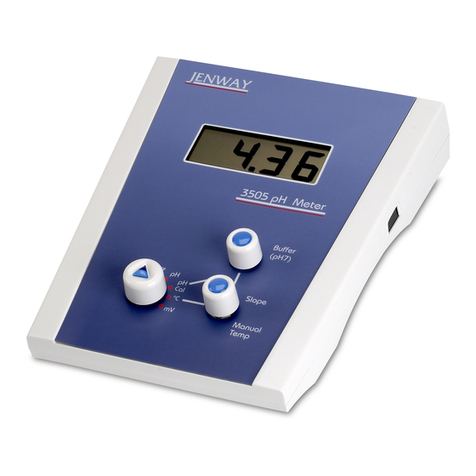
jenway 570 User manual

pH, mV and Temperature Meter
Model 570
Instruction Manual
570 350/Rev B/05-17


3
Safety
Please read this information carefully prior to installing or using this
equipment.
1. The unit described in this manual is designed be to operated only by trained
personnel. Any adjustments, maintenance and repair must be carried out as
dened in this manual, by a person qualied to be aware of the hazards
involved.
2. It is essential that both operating and service personnel employ a safe system
of work, in addition to the detailed instructions specied in this manual.
3. Other than for those items dened in the maintenance procedures herein
there are no user serviceable items in this instrument. Removal of covers and
attempted adjustment or service by unqualied personnel will invalidate the
warranty and may incur additional charges for repair.
4. References should always be made to the Health and Safety data supplied
with any chemicals used. Generally accepted laboratory procedures for safe
handling of chemicals should be employed.
5. If it is suspected that safety protection has been impaired in any way, the unit
must be made inoperative and secured against any intended operation. The
fault condition should immediately be reported to the appropriate servicing
authority.
Merci de lire attentivement ces informations avant d’installer ou d’utiliser
cet appareil.
1. L’appareil décrit dans ce manuel est conçu pour être utilisé uniquement
par des personnes formées. Tout réglage, maintenance ou réparation doit
être effectué comme décrit dans ce manuel, par une personne qualiée
consciente des risques encourus.
2. Il est essentiel que les personnes utilisant et intervenant sur cet appareil
respectent les règles de sécurité de travail, en plus des instructions détaillées
précisées dans ce manuel.
3. En-dehors des éléments décrits dans les procédures de maintenance ci-
incluses, cet appareil ne contient aucun élément réparable par l’utilisateur.
L’enlèvement des capots et les tentatives de réglage ou de réparation par des
personnes non qualiées invalide toute garantie et entraîne un risque de frais
de réparation supplémentaires.

4. Toujours se référer aux ches techniques de santé et de sécurité
accompagnant tout produit chimique utilisé. Respecter les procédures de
laboratoire généralement acceptées pour la manipulation en toute sécurité
des produits chimiques.
5. Si l’utilisateur suspecte qu’un problème quelconque puisse mettre en
cause la sécurité, l’appareil doit être rendu inopérant en empêchant son
utilisation. Communiquer la défaillance constatée au service de maintenance
compétent.
Bitte lesen Sie diese Hinweise vor Installation oder Gebrauch dieser
Ausrüstung sorgfältig durch.
1. Das in diesem Handbuch beschriebene Gerät darf nur von geschultem
Personal bedient werden. Alle Anpassungen, Wartungsarbeiten und
Reparaturen müssen entsprechend der Vorgaben in diesem Handbuch und
von einer kompetenten Person, die mit den damit verbundenen Gefahren
vertraut ist, durchgeführt werden.
2. Es ist wichtig, dass sowohl das Bedienungs- als auch das Service-Personal
zusätzlich zu den detaillierten Anweisungen in diesem Handbuch ein sicheres
Arbeitssystem einsetzen.
3. Mit Ausnahme der Teile, deren Wartungsverfahren in diesem Handbuch
beschrieben sind, enthält dieses Gerät keine weiteren Teile, die vom Benutzer
gewartet werden können. Das Entfernen von Abdeckungen und Versuche
von hierfür unqualiziertem Personal, Anpassungen oder Wartungsarbeiten
durchzuführen, haben zur Folge, dass die Garantie verfällt und können
zusätzliche Reparaturkosten auslösen.
4. Es ist jederzeit auf die sicherheitsrelevanten Daten sämtlicher verwendeter
Chemikalien Bezug zu nehmen. Alle dazu vorhandenen Informationen,
Hinweise und Warnungen zur Handhabung, Lagerung, Verwendung und
Entsorgung müssen genauestens beachtet werden. Allgemein anerkannte
Labormethoden zum sicheren Umgang mit Chemikalien sollten eingesetzt
werden. Es ist jederzeit angemessene Sicherheitsausrüstung und persönliche
Schutzausrüstung zu verwenden.
5. Besteht der Verdacht, dass die Sicherheitsvorrichtungen in irgendeiner Weise
beschädigt wurden, muss das Gerät außer Betrieb genommen und gegen
weiteren Gebrauch gesichert werden. Die Störung sollte der zuständigen
Serviceeinrichtung unverzüglich gemeldet werden.
4

Leggere attentamente queste istruzioni prima di installare o utilizzare il
dispositivo.
1. L’unità descritta nel presente manuale è stata realizzata per essere utilizzata
solo da personale che ha ricevuto l’apposita formazione. Qualsiasi operazione
di regolazione, manutenzione e riparazione deve essere effettuata sulla
base di quanto indicato nel presente manuale da personale qualicato
consapevole dei rischi connessi.
2. È fondamentale che il personale operativo e il personale addetto alla
manutenzione utilizzino un
sistema di lavoro sicuro, oltre a seguire le istruzioni specicate nel presente
manuale.
3. Oltre a quelli indicati nelle procedure di manutenzione, all’interno di questo
dispositivo non sono
presenti altri elementi sui quali è possibile effettuare interventi. La rimozione
delle protezioni e qualsiasi
tentativo di regolazione o di manutenzione posto in essere da personale non
qualicato invaliderà la
garanzia. In questi casi, sarà necessario pagare un importo per le riparazioni
effettuate.
4. È sempre necessario fare riferimento ai dati sulla salute e sulla sicurezza
forniti con le sostanze chimiche utilizzate. Tutte le informazioni, i consigli e
gli avvertimenti disponibili sulla manipolazione, la conservazione, l’uso e lo
smaltimento devono essere rispettati attentamente. Adottare le procedure di
laboratorio generalmente accettate per la gestione delle sostanze chimiche.
Utilizzare sempre attrezzature protettive personali e di sicurezza adeguate.
5. Nel caso in cui si sospetti che la salute possa essere pregiudicata in qualsiasi
modo, disattivare l’unità per renderla inutilizzabile. Qualsiasi condizione
di errore deve essere immediatamente segnalata al responsabile per la
manutenzione.
Lea esta información atentamente antes de instalar o utilizar este equipo.
1. La unidad descrita en este manual está diseñada para que solamente la utilice
personal con formación. Cualquier operación de ajuste, mantenimiento y
reparación debe llevarse a cabo del modo indicado en este manual y debe
realizarla una persona cualicada que sea consciente de los peligros que
implica.
5

2. Es fundamental que tanto los operarios como el personal de servicio utilicen
un sistema de trabajo seguro, así como las instrucciones detalladas que se
especican en este manual.
3. Cualquier elemento que no se encuentre entre los denidos en los
procedimientos de mantenimiento aquí descritos no podrá utilizarse en este
instrumento. La extracción de las tapas y los intentos de ajuste o reparación
por parte de personal no cualicado invalidarán la garantía y pueden incurrir
en cargos adicionales por reparación.
4. Siempre deberían consultarse los datos sobre Salud y Seguridad que se
suministran con cualquier producto químico que se utilice. Deben respetarse
atentamente todas las indicaciones, recomendaciones y advertencias
disponibles en relación con la manipulación, el almacenamiento y la
eliminación de los productos. Es necesario llevar a cabo los procedimientos
de laboratorio de aceptación generalizada para la manipulación segura
de productos químicos. Se deben utilizar en todo momento los equipos
adecuados de seguridad y protección personal.
5. Si existe la sospecha de que las medidas protectoras de seguridad han
quedado dañadas en cualquier modo, la unidad debe inutilizarse y protegerse
contra toda operación que se intente llevar a cabo. El estado de fallo debe
comunicarse inmediatamente a la autoridad de servicio de mantenimiento y
reparación pertinente.
6

7
Contents
Page
SECTION 1 - Introduction 8
1.1 INSTRUMENT DESCRIPTION 8
1.2 INSTRUMENT SPECIFICATION 8
SECTION 2 – Installation 9
2.1 UNPACKING 9
2.2 INSTALLATION 9
2.3 DISPLAY AND CONTROLS 10
SECTION 3 – Temperature Adjustment 12
3.1 MANUAL TEMPERATURE ADJUSTMENT 12
3.2 AUTOMATIC TEMPERATURE CORRECTION (ATC) 12
SECTION 4 – Calibration and Measurement 13
SECTION 5 – Care and Maintenance 15
5.1 BATTERY REPLACEMENT 16
SECTION 6 – Accessories and Spare Parts 17
6.1 OPTIONAL ACCESSORIES 17
6.2 SPARES 17
SECTION 7 – Service and Support 18
7.1 SERVICE 18
7.2 TECHNICAL SUPPORT 18
SECTION 8 – Declaration of Conformity 19

SECTION 1 - Introduction
1.1 INSTRUMENT DESCRIPTION
Model 570 is a general purpose handheld pH, mV and temperature meter
offering 2 point calibration and automatic buffer recognition. This model
simultaneously displays either temperature compensated pH readings or
electrode potential and temperature.
1.2 INSTRUMENT SPECIFICATION
Model 570
Type pH, mV and temperature
Waterproof Yes (IP67)
pH Range -2 to 16pH
pH Resolution 0.01pH
pH Accuracy +/- 0.02pH
mV Range -1000 to 1000mV
mV Resolution 1mV
mV Accuracy +/-1mV
ATC 0 to 100°C
Temperature Range -39.9 to 149.9°C
Temperature Resolution 0.1°C
Temperature Accuracy +/-0.4°C (-10 to 70°C)
No. of Calibration Points 2
Automatic Buffer Recognition Yes – 4, 7 and 10 pH
Auto Shut Off 10 mins
Operating Temperature 0 to 100°C
Battery Life (hours) 2500
pH Connector BNC
Temperature Connector Waterproof Lumberg
screw-locking type
Dimensions (l x w x d) 141 x 71 x 32mm
Weight 230g
Instrument Warranty 2 years
Electrode/Temperature probe Warranty 6 months
8

SECTION 2 - Installation
2.1 UNPACKING
Remove the 570 meter from the packaging and ensure the following items
are included:
Model 570 pH and temperature meter (570 271)
Epoxy bodied combination pH electrode (924 001)
Temperature probe (170 101)
pH 4, 7 and 10 buffer sachets
3 x AAA alkaline batteries (tted)
Instruction manual (570 350)
Jenway Foreign Manual CD (JENMANCD)
2.2 INSTALLATION
Connect the electrode to the BNC socket on the instrument and remove the
protective cap covering the electrode. Connect the temperature probe to the
connector on the instrument and remove the protective sheath. Press the
ON/OFF key to turn the instrument on.
9

2.3 DISPLAY AND CONTROLS
The pH meter has an LCD display which displays either the temperature
compensated pH readings or electrode potential and temperature
simultaneously. The keypad used for this meter enables an easy and effective
way of calibrating and performing a measurement.
1. Display showing pH or electrode potential and temperature reading
2. Connector for temperature probe
3. BNC connector for pH electrode
4. UP arrow Key for adjusting values
5. DOWN arrow Key for adjusting values
6. On/Off key
7. MODE key to change the display between pH or mV and temperature
(single press), changing between °C and °F units (long press)
8. Calibration and Backlight key for calibrating the instrument and
switching on the backlight respectively
Fig. 2.3.1 – Display and Controls
10
1
3
2
4
6
7
85

The instrument will switch off automatically after 10 minutes of inactivity
(i.e. no key presses). To disable the auto-off function press and hold the Up
arrow key whilst switching the unit on. “Auto-off disable” will be displayed
across the screen. When the unit is turned off the auto-off function will be
re-enabled.
To change the instrument temperature units between °C and °F, press and
hold the MODE key for 3 seconds.
When the instrument is turned on a single press of the CAL and backlight key
will turn the backlight on. Another press will switch the backlight off. When
the backlight is on it will automatically turn off after 10 seconds. If the low
battery icon is showing the backlight function will not work.
If mV is selected instead of pH the instrument will read the voltage generated
by a pH, redox or ion type electrode within the range of ±1000mV.
11

SECTION 3 - Temperature Adjustment
Model 570 is supplied with a temperature probe enabling automatic temperature
compensation to be used. If the probe is disconnected then manual temperature
compensation can be used instead.
3.1 MANUAL TEMPERATURE ADJUSTMENT
If the temperature probe is disconnected ‘MANUAL’ will be displayed above
the temperature value. To manually adjust the temperature press or hold the
Up or Down arrow keys to adjust the temperature in whole degrees.
Note that manual temperature adjustment can only be performed if the
temperature probe is not connected.
3.2 AUTOMATIC TEMPERATURE CORRECTION (ATC)
When the temperature probe is connected the 570 meter will automatically
detect the connection and the temperature will be displayed continuously on
the screen. The pH reading will be automatically compensated depending on
the temperature of the sample being measured. The ATC range is 0 to 100°C
(32 to 212°F). If the temperature probe is removed the temperature will be
displayed for 10 seconds.
‘Hi Temp Err’ is displayed if the readings are above 100°C.
‘Lo Temp Err’ is displayed if the readings are below 0°C.
12

SECTION 4 - Calibration and Measurement
Before performing a measurement the instrument must be calibrated. It is
recommended that the instrument is calibrated daily to achieve consistent and
accurate results. Model 570 has a 2 point calibration process. The rst calibration
point MUST be buffer pH 7.00. The second calibration point depends on the
acidity of the solution which is to be measured. For samples with a pH around
5 the second calibration point should be 4.01 pH buffer. For samples with a pH
around 8 the second calibration point should be 10.01pH buffer. Always rinse
the pH and temperature probes in de-ionised water before placing in each buffer
solution. If the ATC probe is connected the instrument automatically compensates
for the resulting change in electrode response due to temperature during the
calibration process.
Press the ON/OFF key to switch the instrument on. If the temperature probe
is not connected ‘MANUAL’ will be displayed above the temperature value. If
manual temperature adjustment is being used, the temperature of the solution
must be measured using a thermometer so that the temperature can be manually
adjusted.
Place the pH electrode and temperature probe into 7.00 pH buffer solution and
allow the reading to stabilise. Stir then press and hold down the CAL key for 3
seconds. Auto-Cal will ash up on the display and then the current reading will be
displayed. Once the reading has stabilised press the CAL key, rinse the electrode
and temperature probe in deionised/distilled water and place them into 4.01 pH
or 10.01 pH solution and allow the reading to stabilise, again stir the solution to
remove any air bubbles. To nish press the CAL key, ‘Calibrated Ok’ will ash up
and the display will show the solution value of the buffer.
To abort the calibration point at any point press the ON/OFF key and the meter will
revert back to any previous calibration values.
During the calibration process the instrument will automatically detect the buffer
solution. However if you know the exact pH value for the buffer at a given
temperature (temperature coefcient) you can change the offset BS (buffer
solution 7.00pH) and slope BS (buffer solution 4.01 or 10.01) by using the Up
or Down arrow keys. Refer to your calibration solutions/capsules temperature
coefcients before any alterations are carried out.
13

‘FAIL’ will be shown if 7.00 pH buffer isn’t used as the rst calibration point.
If the electrode and buffer solution’s combined error is greater than 0.5 pH
or 30mV then ‘Error I/P’ will be displayed and the calibration aborted. If the
electrode and buffer solution’s combined error is greater than 30mV then ‘FAIL’
will be displayed and the calibration aborted. If the electrode and buffer solution’s
combined slope error (4.01 or 10.01) is greater than 0.5pH or 15% ‘Slope error’
will be displayed. If the slope error is greater than 15% the ‘FAIL’ will be displayed.
If an error is displayed during a correctly performed pH calibration this can be
investigated using the mV reading from the pH electrode to determine if the
electrode needs to be replaced. With the instrument in mV mode place the
clean/conditioned electrode and temperature probe into buffer pH 7.00 at a
temperature of 25°C and leave for 30 seconds to stabilise. Record the mV reading
(Asymmetry Potential). Rinse the electrode and temperature probe in distilled or
deionised water, blot and repeat the process in buffer pH 4.01. Record the mV
reading and calculate the difference between the two to obtain the span.
Example:
Reading at 7.00 pH: 4 mV
Reading at 4.01 pH: 178 mV
Span = 178 – 4 = 174mV
In order to calculate the slope percentage (Condition), divide the calculated span
by the theoretical span and times it by 100. The theoretical span between 7.00
pH and 4.01 pH is 176.9 mV.
Slope % = 174/176.9 x 100 = 98%
If your results are below 85% or your mV reading exceeds ±30mV at 7pH, then
you will need to replace the electrode.
Once the instrument is calibrated the sample can be measured. Place the pH
electrode and temperature probe into the sample and allow to stabilise.
If ‘Over Range pH Err’ is displayed the readings are higher than 16pH or 1000mV.
If ‘Under Range pH Err’ is displayed the readings are below -2pH or -1000mV.
If ‘No Probe Err’ is displayed the pH electrode is not connected.
14

SECTION 5 - Care and Maintenance
Over time the electrode sensor will degrade, but regular calibrating, cleaning and
the correct storage will prolong its life. The epoxy bodied combination electrode
supplied with this instrument is suitable for the majority of tests carried out in
aqueous solutions. For other applications, such as low ionic strength, Tris buffers,
high temperatures and strongly acidic solutions a more suitable pH/reference
electrode pair may be required. Details or advice are supplied on request
(cptechsupport@coleparmer.com).
If the electrode readings are slow or erratic, place the electrode into cleaning
solution or 7.00 pH solution for at least half an hour to one hour before testing
again. The temperature probe and pH electrodes are not waterproof and cannot
be fully immersed in water. It is recommended that the instrument is calibrated
daily to achieve consistent and accurate results.
The following general guidelines indicate the care and maintenance required:
Always rinse the pH electrode with cleaning solution or deionised water before
next use.
Electrodes should be stored:
● away from direct sunlight
● in a vertical position
● within their specied temperature range
Always ensure the electrode is used within its specied temperature range. Ageing
of electrodes used above their specied temperature is rapid and irreversible.
DO NOT touch the sensitive glass pH membrane or reference junction. Excess
droplets of solution may be removed by gently blotting with lter paper or tissue.
DO NOT rub the electrode as this may induce an electrostatic charge.
During use ensure the electrode is rinsed between each measurement to eliminate
the contamination of solutions.
15

5.1 BATTERY REPLACEMENT
Replace the battery when the battery icon is low.
This meter will continue to measure accurately but after further usage the meter
will display ‘FLAt bAT’ and shutdown.
Unscrew the screws on the back of the meter and replace with three AAA
batteries ensuring that the polarities are correct.
16

SECTION 6 - Accessories and Spare Parts
6.1 OPTIONAL ACCESSORIES
Part Code Description
025 037 pH 4 buffer (red, 500ml)
025 038 pH 7 buffer (yellow, 500ml)
025 039 pH 10 buffer (blue, 500ml)
025 179 pH 4 buffer sachets (pack of 10)
025 180 pH 7 buffer sachets (pack of 10)
025 181 pH 10 buffer sachets (pack of 10)
025 192 pH electrode storage solution (250ml)
025 161 pH electrode cleaning solution (500ml)
570 401 White silicon case for 570 pH meter
570 402 Blue silicon case for 570 pH meter
6.2 SPARES
Part Code Description of Spare Part
924 001 Epoxy bodied electrode
170 101 Temperature probe
033 275 Carry Case
17

SECTION 7 – Service and Support
7.1 SERVICE
Our dedicated service staff are on hand to help in the unlikely event that your
Jenway equipment develops a fault. Please contact them by one of the following
means with a clear description of the problem:
E-mail: cpservice@coleparmer.com
Tel: +44 (0) 1785 810475
On occasion it may be necessary for your equipment to be sent back to our
Service Department for repair. In this case please contact the Service Department
for a reference number which you should include with your faulty equipment.
Please also ensure you include a clear description of the fault and a completed
copy of our Decontamination Certicate. Please clearly mark the package for the
attention of the Service Department and post to the following address:
Cole-Parmer Ltd.
Beacon Road,
Stone,
Staffordshire,
ST15 0SA,
United Kingdom
All replacement parts are guaranteed for 6 months and where ever possible,
returned equipment is turned around in 5 working days.
7.2 TECHNICAL SUPPORT
Jenway have a dedicated Technical Support team made up of experienced
scientists who are on hand to help with any applications advice and questions you
may have about our products and how to use them. If you require any technical
or application assistance please contact the team at:
E-mail: cptechsupport@coleparmer.com Phone: +44 (0)1785 810433
18

SECTION 8 – Declaration of Conformity
and so we cannot guarantee that interference will not
occur in practice. Where there is a possibility that injury,
damage or loss might occur if equipment malfunctions
due to radio frequency interference, or for general
advice before use, contact the manufacturer.
This product meets the applicable EC
harmonised standards for radio frequency
interference and may be expected not to
interfere with, or be affected by, other equipment with
similar qualifications. We cannot be sure that other
equipment used in its vicinity will meet these standards
Plastic materials and articles intended to come into contact
with food.
Materials and articles intended to come into contact with
food.
Registration, Evaluation, Authorisation and Restriction of
Chemicals (REACH).
EU Regulation 10/2011
EC Regulation 1935/2004
EC Regulation 1907/2006
EU Declaration of Conformity
This declaration of conformity is issued under the sole responsibility of the manufacturer
Signed for and on behalf of the above manufacturer
Product Laboratory Equipment
Manufacturer Cole-Parmer Ltd
Beacon Road
Stone, Staffordshire
ST15 0SA
United Kingdom
File Number P225
Authorised Cole-Parmer
Representative Beacon Road
Stone, Staffordshire
ST15 0SA
United Kingdom
Object of Declaration Portable pH Meters
(reference the attached list of catalogue numbers)
The object of the declaration described above is in conformity with the relevant Union Harmonisation Legislation:
Additional Information
Place of Issue
Date of Issue
Authorised Representative
Title
Signature
Year of CE Marking: 2016
Stone, Staffordshire, UK
02 March 2016
Steve Marriott
Technical Director
References to the relevant harmonised standards used or references to the other technical specications in relation
to which conformity is declared:
IEC/EN 61010-1:2010
Safety requirements for electrical equipment for
measurement, control and laboratory use.
Part 1: General requirements.
Electrical equipment for measurement, control and
laboratory use. EMC requirements.
Part 1: General requirements (Class A).
IEC/EN 61326-1:2013
Low Voltage Directive
EMC Directive
RoHS Directive
2014/35/EU
2014/30/EU
2011/65/EC
Declaration of Conformity is also available to view online at www.jenway.com

Cole-Parmer Ltd.
Beacon Road,
Stone,
Staffordshire,
ST15 0SA,
United Kingdom
Tel: +44 (0)1785 812121
Email: cpinfo@coleparmer.com
Web: www.jenway.com
Table of contents
Other jenway Measuring Instrument manuals
Popular Measuring Instrument manuals by other brands

Shot-Scope
Shot-Scope PRO L1 user manual

WATANABE ELECTRIC INDUSTRY
WATANABE ELECTRIC INDUSTRY AL-512 Series instruction manual
Tracon
Tracon TVO-F3-4MCTA user manual
YOKOGAWA
YOKOGAWA FLXA202 technical information
Yealink
Yealink BLT60 Direction for Installation and Use
FLIR
FLIR EXTECH HDV-WTX1 Informational sheet
Fluidwell
Fluidwell F Series Operation manual
EUTECH INSTRUMENTS
EUTECH INSTRUMENTS STANDARD PHSCAN 2 PH TESTER Caractéristiques

Hanna
Hanna HALO2 instruction manual

HODAKA
HODAKA HT-1200N operating manual
PCB Piezotronics
PCB Piezotronics 3501B1260KG Installation and operating manual
Secure
Secure APEX 100 user manual
