Jeremias HT 103 User manual

1
Jeremias INSTALL_HT Rev: 3/26/19
Type HT Chimney
UL Listed to:
•UL 103 HT Factory-Built Chimneys for Residential Type and Building Heating Appliances
•CAN/ULC-S604 STANDARD FOR FACTORY- BUILT TYPE A CHIMNEYS
Model HT - Double Wall 1” Fiber Insulation
Installation Instructions
A MAJOR CAUSE OF CHIMNEY RELATED FIRES IS FAILURE TO MAINTAIN REQUIRED
CLEARANCES (AIR SPACES) TO COMBUSTIBLE MATERIALS. IT IS OF UTMOST IMPORTANCE
THAT THIS CHIMNEY BE INSTALLED ONLY IN ACCORDANCE WITH THESE INSTRUCTIONS.
Important: Read all instructions before beginning to install. Failure to comply with these instructions may result in
a hazardous installation resulting in injury or damage to property. An improper installation will void the
manufacturer’s warranty.
Keep these instructions for future reference.
For Technical Support or more product information please contact us at 678-388-2740 or visit our website at
www.jeremiasinc.com

2
Jeremias INSTALL_HT Rev: 3/26/19
INDEX
Pg.
Description
8
Extended Wall Brackets (EWB)
2
Listings
8
Wall Thimble (WT)
2
Codes and Permits
9
Tee with Cap (TWC)
3
Product Code Key
9
Tee Support (TS)
3
General Installation Requirements
9
Tee Support Extended Brackets (SEB)
3
Termination Requirements
10
Roof Support (RS)
4
Suggested Tools, Equipment & Hardware
10
Anchor Plate (AP)
4
Clearances
11
Elbow Offset / Elbow Strap (ES)
4
Minimum Framing Dimensions
11
Firestop Radiation Shield (FRS)
4
Support Spacing
11
Attic Insulation Shield (AIS)
4
Chimney Size
12
Flat & Pitch Roof Flashings (FRF & PRF)
4
Chimney Location
12
Storm Collar (SC)
4
Chimney Length
12
Rain Cap (RC)
5
Joint Assembly
13
Spark Arrestor (SA)
5
Joint Assembly - Alternate
13
Telescopic Roof Brace (TRB)
6
Cutting Pipe to Length
13
Final Check
6
Ceiling Support Box Square & Round (CS & CSR)
13
Important Notice
7
Chimney Adapter (AD)
13
Operation and Maintenance
7
Adjustable Wall Bracket (AWB)
14
Installation Examples
15
Warranty
Introduction
Jeremias HT Chimney provides the highest quality product in its class. It features all welded inner and outer pipes, flue gas pipes made of 316L
Stainless Steel, a unique design which leaves no destructive heat bridge between inners and outers and a strong, simple locking band design which
makes for easy assembly. Certification by Underwriters Laboratory and a best-in-class warranty assure you the finest possible product.
Chimney Applications
HT Chimney is for use with heating appliances utilizing solid fuels, oil, gas (propane or natural) or coal as prescribed by the appliance manufacturer.
These include free standing wood stoves, fireplace inserts, fireboxes, fireplaces, furnaces, cook stoves, boilers and water heaters that require a
UL103HT chimney system. Do not use with forced draft positive pressure appliances.
You must not mix parts or products from any other venting system or supplier. Do not install damaged or modified parts.
Listings
Jeremias HT Chimney is tested and listed to UL 103 HT Standard for Factory-Built Chimneys for Residential Type and Building Heating Appliances
for 5, 6, 7 & 8” diameter. And, in Canada CAN/ULC-S604 STANDARD FOR FACTORY- BUILT TYPE A CHIMNEYS.
UL Product Labels
Codes and Permits
Your installation must be in conformance with the current version of NFPA 211 and local or state building codes, whichever has jurisdiction.
ALWAYS CONTACT LOCAL BUILDING OFFICIALS OR FIRE OFFICIALS REGARDING PERMITS, RESTRICTIONS AND INSTALLATION
INSPECTIONS REQUIRED IN YOUR AREA.

3
Jeremias INSTALL_HT Rev: 3/26/19
Product Code Key
Each part manufactured by Jeremias is identified with a product code. The product code contains the Model, Vent size, Part ID, and Other
information.
Part Number Example:
HT
06
-
SS
12
|
|
|
|
Model
Chimney
Diameter
Material
Product ID
5" to 8"
SS = 316ss Inner / 304ss outer
GAL = 316ss Inner / Galv Outer
Product ID
AD = Chimney Adapter
LB = Locking Band
CSRT = Round Ceiling Trim
AP = Anchor Plate
12 = 12” Length
SA = Spark Arrestor
IS = Attic Insulation Shield
18 = 18” Length
SC = Storm Collar
RC = Rain Cap
24 = 24” Length
TWC = Tee with Cap
ELKT = Elbow Kit (Degree)
36 = 36” Length
CSS = Ceiling Support Square
ELS = Elbow Strap
48 = 48” Length
TS = Tee Support
ERB = Extended Roof Brace
AVL = Adjustable Vent Length
WB = Wall Bracket
FRS = Firestop Radiation Shield
RS = Roof Support
WT = Wall Thimble
FRF = Flat Roof Flashing
RST = Trim Collar
PRF = Pitched Roof Flashing
CSR = Round Ceiling Support
General Installation Requirements
•Except for installation in one or two-family dwellings, a factory-built chimney system that extends through any zone above that on which the
connected appliance is located, shall be provided with an enclosure having a fire resistance rating equal to or greater than that of the floor
or roof assemblies through which it passes.
•Chimney to be sized in accordance with the appliance manufacturer’s instructions.
•Parts of the chimney system below the roofline should be enclosed to help reduce condensation, creosote buildup and improve draft.
•Creosote and soot –formation and need for removal: When wood is burned slowly, it produces tar and other organic vapors, which
combine with expelled moisture to form creosote. The creosote vapors condense in the relatively cool chimney flue of a slow-burning fire.
As a result, creosote residue accumulates on the flue lining. When ignited this creosote makes an extremely hot fire. The chimney should
be inspected once every 2 months during the heating season to determine if a creosote or soot buildup has occurred. If creosote or soot
has accumulated, it should be removed to reduce the risk of chimney fire.
•To clean and inspect: Open or remove termination cap or cleanout tee to access the chimney.
•Contact local building or fire officials about restrictions and installation inspection in your area.
•Every chimney system must be planned and installed for performance and safety.
•Refer to the appliance manufacturer’s instructions to determine venting requirements and limitations with respect to the installation and use
of the appliance.
•Maintain rated clearances to combustibles over the entire length of the vent system.
•Do not field install insulation in any required clearance around the chimney system
•Reference the appliance manufacturer’s installation and operating guides for maintaining ventilation and air circulation where required
•For planning and clearance purposes, nominal OD of chimney always equals ID plus 2”, example = 6” Chimney OD is 8”
•Not all appliances are listed for use in mobile homes and may require special considerations. Refer to the appliance safety manual
carefully.
Termination Requirements
In accordance with National Fire Protection Association Standard #211, the chimney must terminate at least 3 feet above the roof top penetration
and 2 feet higher than any structure within a 10-ft. radius (see Fig 17). Chimney heights greater than 5 feet above the roof line must use additional
support bracing. See Telescopic Roof Brace (TRB) section for instructions.

4
Jeremias INSTALL_HT Rev: 3/26/19
Suggested Tools, Equipment & Hardware
Safety Glasses
Drill
Plumb Bob, Level & Tape Measure
Abrasive Cutting Wheel/Grinder
Safety Gloves
Hammer
Caulk Gun
Power drill / screw / nut driver
Screwdrivers
Metal Snips
Ladder
5/16” Nut driver / socket wrench
High Temp Sealant
8-penny nails
#8 1-1/2” x 2-1/2” screws
Roofing Nails
Reciprocating & Keyhole Saws
Framing Square
Clearances
Maintain a 2” MINIMUM AIR SPACE CLEARANCE BETWEEN INSULATED CHIMNEY
SECTIONS AND COMBUSTIBLE MATERIALS. Never fill any required clearance space
with insulation or any other materials. Combustibles include lumber, plywood, sheetrock,
plaster and lathe, electrical wiring and insulation. Observe all clearance and set back
requirements for your appliance and connecting stove pipe as stated by the manufacturer.
See Fig. 1.
Minimum Framing Dimensions though Wall or Ceiling
Where the chimney passes through the wall or ceiling, minimum Clearance to Combustibles
must be maintained. See Table 1. For Minimum Framing Requirement. Framing should be
square (all 4 sides) and provide support for attaching chimney system assemblies. See Fig
2.
Table 1. Minimum Framing Requirements
Component
5” Diameter
6” Diameter
7” Diameter
8” Diameter
Ceiling Support –Round or Square
11¼” x 11¼”
12¼” x 12¼”
13¼” x 13¼”
14¼”x 14¼”
Wall Thimble
11¼” x 11¼”
12¼” x 12¼”
13¼” x 13¼”
14¼”x 14¼”
Firestop Radiation Shield
11¼” x 11¼”
12¼” x 12¼”
13¼” x 13¼”
14¼”x 14¼”
Attic Insulation Shield
11¼” x 11¼”
12¼” x 12¼”
13¼” x 13¼”
14¼”x 14¼”
Note: Framing dimension tolerance may be up to ½” larger but not smaller than the specified value.
Table 2 –Maximum Support Capacity / Spacing
Component
Vertical Support Height / Spacing
Tee Support (TS)
52’(16m)
Adjustable Wall Bracket (AWB)
10’ (3m)
Extended Wall Bracket (EWB)
8’ (2.5m)
Ceiling Support Square (CS)
44’ (13.4m)
Ceiling Support Round (CSR)
44’ (13.4m)
Anchor Plate (AP)
52’ (16m)
Roof Support (RS)
12’ (3.7m)
Elbow Support
Each Offset
Tee Support
Extended (SEB)
Distance from Wall
2” to 4”
5” to 10”
11” to 14”
Height
24’
18’
16’
Chimney Size
Refer to the appliance manufacturer’s installation instructions for proper sizing and chimney
configuration.
Chimney Location
Locate the appliance so the chimney and chimney connector are straight and short as possible. Try to avoid modifications to structural components
and other building components (Joists, studs, electrical, plumbing, etc.).
Chimney Length
Due to the engagement of the chimney sections, the effective installed length of any chimney pipe or fitting is 2-3/16” less than the described length.
Fig 2. Framing Dimension
Fig 1. Minimum 2” Clearance
5
Jeremias INSTALL_HT Rev: 3/26/19
Enclosures
It is recommended that the Chimney be installed within the building
envelope to help reduce condensation, creosote buildup and improve
draft. The chimney should be enclosed where it passes through
occupied spaces, closets, storage areas or any place where the chimney
surface could be contacted by persons or combustible materials. In cold
climates, exterior chimney systems should be enclosed in a chase.
Maintain the 2” clearance to combustibles for all enclosures.
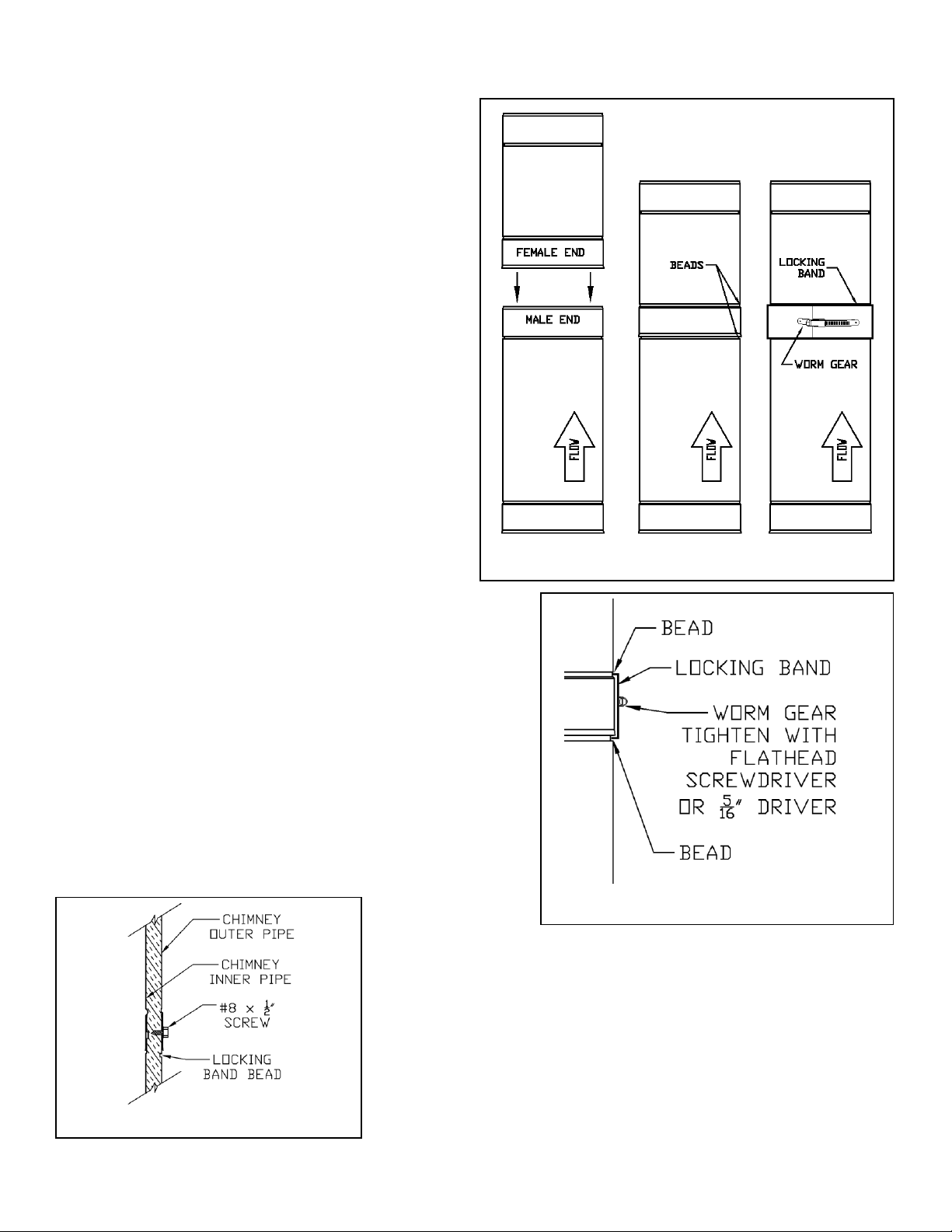
Joint Assembly –Locking Band
HT Chimney segments are joined together with a Locking Band (LB) to
create a complete chimney system.
To install (See Fig 3 & 4):
1. Orient the Chimney so the Flow arrow on the label is pointing
up and away from the appliance.
2. Slide the female end down over the male end. Apply pressure
and twist the vent to fully engage the sections. The vent
lengths will reach a mechanical stop when fully engaged.
3. Note: The Locking Band is not symmetrical and must be
oriented correctly. Position the Locking Band so that the
number etching is right-side-up. When viewing the worm gear
straight on, the nut is to the left. With the worm gear rotated to
away from sight, the nut can be accessed with a screw driver
in your right hand.
4. Position the Locking Band around the joint capturing the beads
from each pipe.
5. Use either a 5/16” socket or standard screwdriver to tighten
the screw on the LB until it is snug, then tighten an additional
1/4 turn.
Joint Assembly - Alternate
HT Chimney segments can be joined together with screws instead of using a
locking band.
To Install (See Fig 5):
1. Orient the Chimney so the Flow arrow on the label is pointing up and
away from the appliance.
2. Slide the female end down over the male end. Apply pressure to fully
engage the sections. The vent lengths will reach a mechanical stop when
fully engaged.
3. Screw #8x1/2 long self-drilling screws, through the overlapping chimney
joint. Only penetrate the outer wall of chimney. Install minimum of 3
screws. Caution: Do not drill more than ½ deep into chimney pipe.
4. Apply High Temperature (250°F) Silicone sealant over each screw to
eliminate moisture penetration.
Fig 3. HT Joint Installation
Fig 4. HT Joint / Cut-away view
Fig 5. Alternate Screw Joint

6
Jeremias INSTALL_HT Rev: 3/26/19
Cutting Pipe to Length
Standard pipe can be cut in the field to create a specific length where standard Fixed Lengths
will not suffice. In this situation, screws are used instead of the Locking Band.
To Install (See Figs 6a-6d.):
1. Measure the length of vent required.
2. Add 2-3/16” to the required length to determine the overall cut length needed.
3. Measure from the Bottom (inlet) end up to the length determined in Step 2. Mark
cut line around the entire pipe circumference.
4. Use abrasive cutting wheel or snips to cut along the mark line in step 2. Remove
the Excess Length of the Outer Jacket.
5. With the insulation & inner pipe now exposed, slide the inner pipe and insulation so
that it is flush with the cut edge of the outer.
6. Use box cutter or knife to cut the insulation and expose the inner liner.
7. Use cutting wheel to cut the inner liner so that it is flush with the insulation and outer
jacket.
8. Install length as described in Joint Assembly –Alternate section.
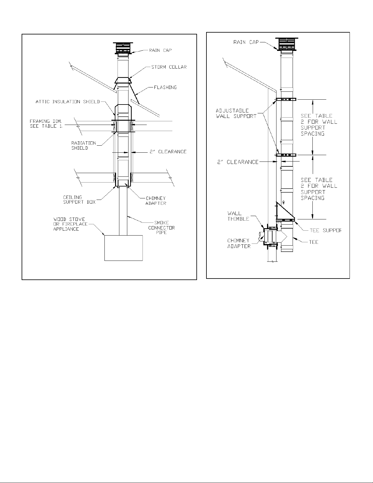
Ceiling Support Square & Round (CS & CSR)
The Ceiling Support Box is used to provide support and allow the chimney to pass through a flat
or pitched cathedral ceiling in the room above where the appliance is located.
To install (See Fig. 8, 7, 9 & 29):
1. Determine the location where the chimney will pass through the ceiling. Plan the
system to avoid obstructions such as electrical, plumbing and studs. Ensure required
clearance to combustibles is maintained including clearance to pitched ceiling.
2. Establish a framed opening. Refer to Table #1 for proper Framing dimensions. Refer
to Table #2 for maximum Support height.
3. Position the Support Box inside the framed opening. Adjust the Ceiling Support
vertically within the framed opening. The Square portion must protrude a minimum of
2” into the finished ceiling.
a. Two L-brackets are included with each CS. These L-brackets provide
temporary support to the CS while it is being installed. Measure the thickness
of the framing materials to determine the location where the L-brackets
should be positioned. Mark the location and secure L-brackets to the outside
surface of the support box using the self-drilling screws provided.
4. Secure the Ceiling Support by driving a minimum of two x 2” screws (provided) per side
(minimum of 8 screws total) through the Ceiling Support box and into the framed
opening. Alternatively, three 8-penny nails per side can be used.
Fig 6a. Cutting to Length
Fig 7. Ceiling Support
Fig 6b. Cut / Remove Outer
Fig 6c. Slide Outer Up
Fig 6d. Cut & Remove Inner

7
Jeremias INSTALL_HT Rev: 3/26/19
5. Ceiling Support Square (Only) - U-Shaped trim plates are used to
close off any gaps around the Ceiling Support and provide a
finished look.
a. Position 1st U-Shaped trim plate around the ceiling box
and flush with the ceiling surface. Secure with two, 2”
screws (provided) in the corners of the trim plate.
b. Position 2nd U-Shaped trim plate around the opposite
side of the box. The extended legs will overlap the 1st U-
Shaped bracket. Secure with two, 2” screws (provided)
in the corners of the trim plate and two screws through
the pilot hole that overlaps the 1st bracket.
6. Ceiling Support Round (Only) –
a. For installation in a flat ceiling a donut shaped trim collar
is provided to close off any gaps around the Ceiling
Support and provide a finished look. Position the donut
trim plate around the ceiling support and secure with
screws provided.
b. For installation on pitched ceiling, an oval shaped pitched
collar is available. Select the collar to meet the pitch of the ceiling. Secure collar to ceiling with fasteners provided.
7. Connect Chimney Adapter to the 1st length of chimney pipe. Refer to Joint Assembly section.
8. Lower Chimney Adapter and Chimney Pipe assembly down into the Ceiling Support. Align and engage the single-wall tube of the
Chimney adapter through the hole in the ceiling support.
Chimney Adapter (AD)
The Chimney Adapter is used to adapt smoke pipe to double-wall chimney.
To Install (See Fig 10):
1. Connect AD to chimney section. Refer to Joint Assembly section for details.
2. Position the Chimney Adapter as described in Ceiling Support Box or Wall Thimble section.
3. Engage smoke pipe such that the single-wall of the Chimney Adapter extends down inside
the smoke pipe.
4. Secure smoke pipe to Chimney adapter with ½” self-drilling screws through adapter or as
described by smoke pipe manufacturer.
Adjustable Wall Bracket (AWB)
The Adjustable Wall Bracket is used to provide lateral support for the chimney. The AWB provides
adjustable distance from the wall.
To Install (See Fig 11 & 30):
1. Refer to Table 2 for required maximum spacing distance.
2. Secure mounting bracket to wood stud or suitable solid structure with 5/8” lag bolts.
3. Route vent through clamp band and secure by tightening Clamp Band Bolts.
Fig 11. Adjustable Wall Bracket (AWB)
Fig 9. Ceiling Support
Square (CS)
Fig 10. Chimney Adapter
Fig 8. Ceiling Support
Round (CSR)
8
Jeremias INSTALL_HT Rev: 3/26/19
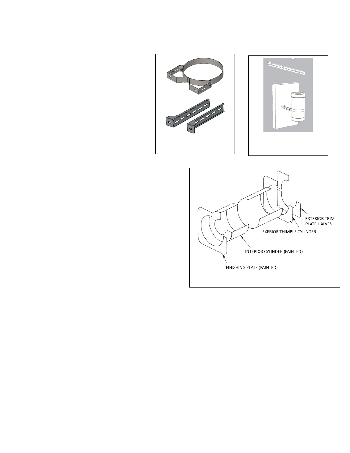
Extended Wall Bracket (EWB)
The Extended Wall Brackets are adjustable to provide lateral support for the chimney for up to 14” away from the wall. This allows the chimney to
clear roof overhang or other obstacles.
To Install (See Fig 12, 13 & 30):
1. Refer to Table 2 for required minimum spacing
distance.
2. Determine location and required distance chimney
will be from the wall.
3. Position the wall band on the extended bracket,
adjust to the required location, align clearance holes
and secure each leg bracket to the band using 2
bolts each. Note; the wall brackets can be
positioned with the mounting feet pointing inwards
or out.
4. Secure brackets to wood stud or suitable solid
structure with 5/8” lag bolts.
5. Route vent through clamp band and secure by
tightening Clamp Band Bolts.
Wall Thimble (WT)
A Wall Thimble is required where the chimney passes through a combustible
wall. The Wall Thimble includes 2 cylinders that telescopically adjust to fit the
thickness of the wall.
To Install (See Fig. 14 & 15):
1. Determine the location where the chimney will pass through the wall.
Plan the system to avoid obstructions such as electrical, plumbing
and studs.
2. Cut a hole in the wall and build a framed in opening. Refer to Table
#2 for proper framing dimensions.
3. From the outside, position the cylinder of the (unpainted) Exterior
Thimble in the framed opening. Secure plate to exterior wall using
four 2” long screws (provided).
4. Install Tee Support (See Tee Support section)
5. Install Tee with Cap ((See Tee Support section)
6. From the inside, align the (painted) cylinder with the chimney
adapter exterior cylinder from Step #3.
7. Engage (painted) telescopic cylinder until it contacts the Chimney
Adapter (AD). Ensure that minimum 4” of chimney pipe and (painted)
cylinder extends beyond the finished wall.
8. Install Wall Thimble Finishing Plate over (painted) cylinder. Secure
with four (black) 2” long wood screws provided.
9. From the exterior, position Exterior-Trim-Plate-Halves against exterior plate and round tee branch perimeter. Secure with two #8 Self-
drilling screws.
10. Use high-temperature sealant (500°F) to seal around chimney length, seams and all plates.
Fig 14. Wall Thimble
Fig 12. Extended Wall
Bracket (EWB)
Fig 13. Extended Wall
Bracket (EWB)

9
Jeremias INSTALL_HT Rev: 3/26/19
Tee with Cap
The Tee is used when the chimney passes horizontally through a wall to a vertical
chimney. The Tee Cap is located under the Tee to collect ash. The Tee Cap can be
removed to provide access to the chimney for inspection and cleaning (See Chimney
Maintenance and Cleaning section). When locating the Tee & Cap, ensure required
clearance to combustibles are maintained including clearance under the tee cap for
access and removal.
To Install (See Fig 15):
1. Determine the location where the chimney will pass through the wall.
2. Install Wall Thimble.
3. Install Tee Support.
4. Determine the length of chimney pipe required to pass through the wall
and extend a minimum 4” beyond the finished wall.
5. Connect chimney length to the Tee branch. Secure length with locking
band.
6. Position the Tee branch inside the Wall Thimble and secure the Tee to the
Tee Support (TS) with Locking Band.
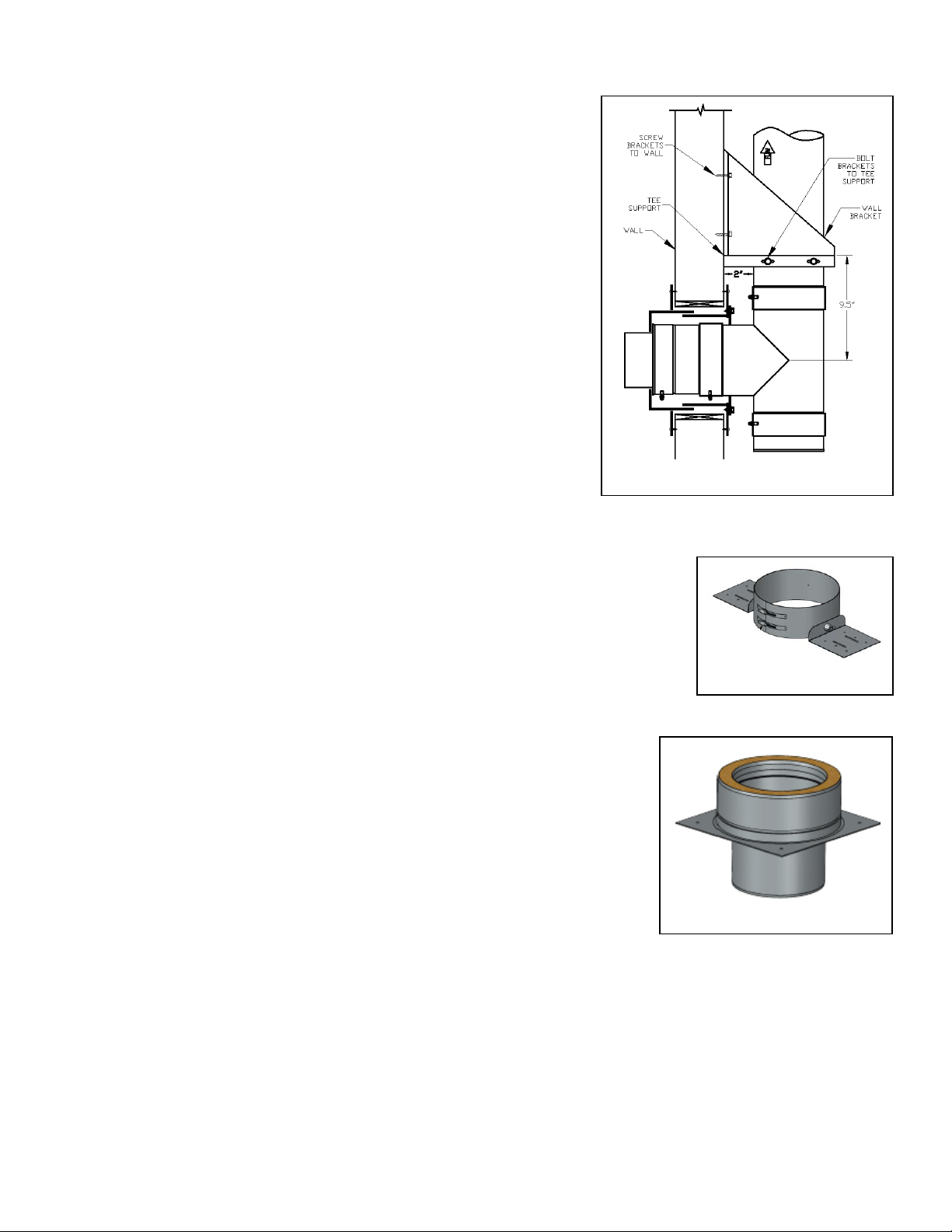
Tee Support (TS)
The TS is a section of chimney that is used to provide vertical support. The Tee can
be suspended below the TS or positioned on top of the TS. The TS Wall Brackets
can be installed below the TS or above the TS.
To Install (See Fig 15, 16, 17 & 18):
1. Refer to Table 2. For maximum chimney height Extended Brackets and
support.
2. Use supplied fasteners to bolt Wall Brackets to TS in the desired position
(above or below the TS).
3. Position the Tee Support against the wall it will be mounted to. The plate
of the TS should be located 9.5” above (or below) the centerline of the Tee branch, where the
branch passes through the wall thimble. Secure TS Wall Brackets to the wall. Ensure Wall
Brackets are mounted to joist or other solid structure.
4. Install adjoining chimney lengths as described in Joint Assembly section.
Tee Support Extended Brackets (SEB)
The SEB allows the Tee Support plate to be adjusted up to 14” away from the wall surface. The
Support Extended Brackets are use with the standard Tee Support Plate. The brackets can be
positioned above or below the Tee support.
To Install (See Fig.17)
1. Refer to Table 2. Do not exceed the maximum chimney height Extended Brackets can
support. Note that the support height varies based on the distance the chimney pipe is from
the wall.
2. Determine where the tee is to be located. Position the Tee Plate on the Brackets and use
supplied fasteners to bolt SEB Brackets to the Tee Support Plate.
3. Secure SEB Brackets to the wall. Ensure Wall Brackets are mounted to joist or other solid
structure.
4. Install adjoining chimney lengths as described in Joint Assembly section.
Fig 15. Wall Thimble & Tee
Fig 16. Tee Support (Wall
brackets below support)
Fig 17. Tee Support
Extended Brackets (SEB)
10
Jeremias INSTALL_HT Rev: 3/26/19
Roof Support (RS)
The Roof Support (RS) provides vertical support for the chimney both above and suspended
below the Roof Support. It may also be used to provide supplemental support when the total
chimney height exceeds the capacity of the primary support.
To Install (See Fig. 19)
1. Refer to Table 2–Maximum Support Capacity / Spacing. Do not exceed the
maximum chimney height the RS can support.
2. Determine where the RS is to be located. The brackets of the RS are to be
positioned on top of framed roof opening, rafters or other solid surface.
3. Ensure minimum 2” clearance to combustible materials is maintained.
4. Position the RS around the chimney leaving the band loose so the Roof support can
be adjusted.
5. Locate the Brackets on top of framing. Align pilot holes with wood rafters. Use a
minimum of three #10 x 2-1/2” wood screws to secure each bracket to wood rafter.
6. Tighten worm gears to clamp RS to chimney pipe
7. Secure RS to Chimney Pipe by driving one #10 x 1/2” long self-drilling screw
through the pilot hole in the RS band and into the outer casing of the Chimney Pipe.
Note: Do not puncture the inner flue pipe with screw.
8. Install adjoining chimney lengths as described in Joint Assembly section.
Anchor Plate (AP)
The Anchor Plate (AP) connects a masonry fireplace or a factory-built fireplace to Jeremias
HT chimney.
To Install For Masonry fireplace(see Fig 20) :
1. Follow the requirements of the local building code for connecting factory-built chimney to masonry fireplace.
2. Refer to Table 2–Maximum Support Capacity / Spacing. Do not exceed the maximum chimney
height the AP can support.
3. Ensure the top of the masonry is structurally sound and has level surface. Correct any masonry
issues accordingly.
4. Apply 1,000°F High temperature sealant around flue opening
5. Position the Anchor Plate over the fireplace opening.
6. Mount AP to fireplace with (4) masonry anchors
7. Install adjoining chimney lengths as described in Joint Assembly section.
To Install for factory-built fireplaces:
1. Read and comply with the fireplace manufacturers installation instructions. Verify model HT chimney
is approved for use with the appliance.
2. Refer to Table 2–Maximum Support Capacity / Spacing. Do not exceed the maximum
chimney height the AP can support.
3. Refer to fireplace manufacturers instructions regarding application of 1,000°F High
temperature sealant around flue opening
4. Position the Anchor Plate over the fireplace opening.
5. Mount AP to fireplace with (4) 5/8” stainless steel sheet metal screws
6. Install adjoining chimney lengths as described in Joint Assembly section.
Fig 18. Tee Support (above Tee)
Fig 19. Roof Support
Fig 20. Anchor Plate

11
Jeremias INSTALL_HT Rev: 3/26/19
Elbow Offset
An elbow offset may be necessary to avoid interference with joists or other obstacles. The maximum
offset angle is 30 Degrees. Maximum of 1 offset (2 elbows) per installation. Maximum horizontal
offset distance between elbows is 8 ft. The Elbow Offset must be supported with an Elbow Strap or
other support.
To Install (See Fig. 21)
1. Attach (lower) Elbow to chimney section & secure with locking band (see Joint Assembly
section).
2. Attach offset length (Maximum 8 ft. offset length). During installation provide support to
offset to avoid stress on elbow.
3. Install Elbow Strap to support the chimney.
a. Position Elbow Strap at the top of the offset immediately before the second elbow.
b. Tighten band of the Elbow Strap around offset
c. Attach Elbow Support Straps to framing member or other support member
d. Fix Straps to framing member with 2 x 8-Penny nails or 2 x #8, 1-1/2” long
screws.
4. Attach the second (upper) Elbow to the offset and secure with locking band (see Joint
Assembly section).
Firestop Radiation Shield (FRS)
A Firestop Radiation Shield is required in multistory installations at each location where the chimney passes
through a ceiling or floor. The FRS is not required where a Ceiling Support Box is installed or where the chimney
penetrates through the roof. The FRS is installed on the underside of the ceiling/floor with the cylinder positioned
vertically inside the framed opening.
To Install (See Fig 22 & 23):
1. Establish the correct framing dimension (See Table 2)
2. From the underside of the ceiling, position the cylinder of the FRS inside the framed opening and with
the plate flat against the ceiling surface. Note: The FRS has 1” square standoffs that should align
inside the ceiling joist to ensure the minimum framed opening is established. The cylinder should
extend the entire length through the framing. If the cylinder extends beyond the top side of the joist, it
may be necessary to trim the cylinder so that it does not interfere with the AIS installed on top of the
joist.
3. Secure the FRS with four 8-penny nails (or 1-1/2” screws) through the pilot holes provided.
4. Route chimney sections through the opening in the Radiation Shield.
Attic Insulation Shield (AIS)
The Attic Insulation Shield is required where an unenclosed chimney passes into an unenclosed space such as an attic. The function of the AIS is to
keep combustible materials away from the chimney. The AIS is mounted on top of
ceiling/floor joists and extends upward to provide shielding from insulation. The AIS is
made of 2 telescopic cylindrical shields that can be adjusted to the required height.
To Install (See Fig. 23 & 24):
1. Establish a framed opening in the floor joist. Refer to Table 2. For correct
framing dimension.
2. Assemble chimney such that at minimum 18” of chimney extends up through
the framed opening.
3. Slide the AIS down over the chimney and position the plate of the AIS on the
framed opening.
4. Secure the AIS to the framed opening using the screws provided
Fig 23. FRS & AIS
Fig 22. Firestop
Radiation Shield
Fig 21. Elbow strap
12
Jeremias INSTALL_HT Rev: 3/26/19
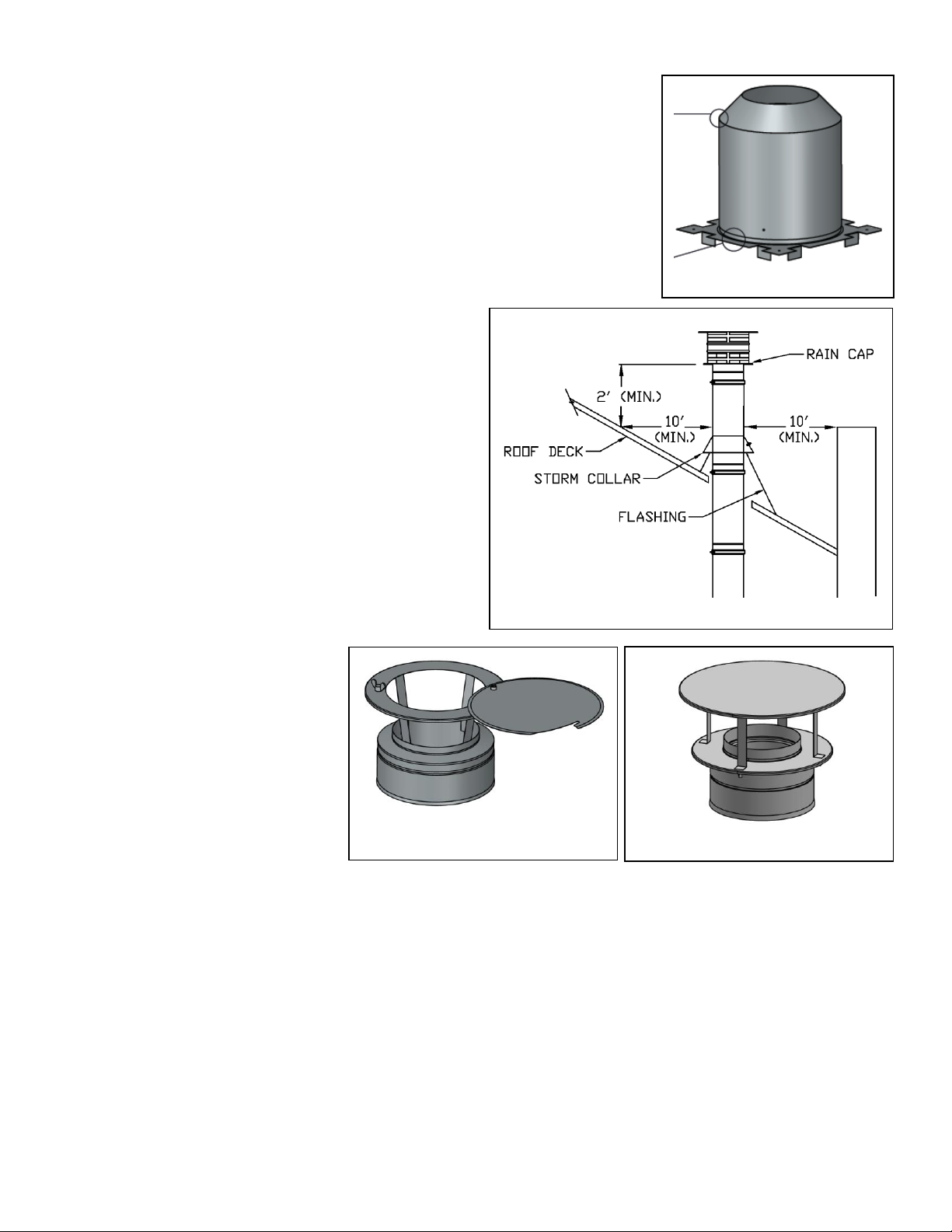
Flashings
A flashing is used to seal off the opening where the vent passes through the roof. Choose the correct
flashing to match the vent size and pitch of the roof.
To install (See Fig 25):
1. Ensure the proper clearance to combustibles is maintained.
2. Position the flashing over the vent. The upper end of the flashing is installed underneath the
roofing material. The lower end of the flashing is installed on top of the roofing material.
3. Seal the flashing in place and secure with 2 roofing nails.
Storm Collar (SC)
A Storm Collar is used to seal off the opening between the vent and flashing.
To Install (See Fig 25):
1. Position Storm Collar around vent and against the opening of
the flashing.
2. Tighten worm gear to secure Storm Collar in place.
3. Apply sealant around seam between Storm Collar and vent.
Rain Cap (RC)
The Rain Cap is used to terminate the chimney system and prevent rain,
animals, insects and other debris from entering the chimney system. The
Rain Cap has a pivoting top to allow access for inspection and cleaning.
To install (See Fig 26):
1. Verify Rain Cap location conforms to details in Termination
Requirements section.
2. Position Rain Cap on Chimney and secure. Refer to Joint
Assembly section.
Fig 26. Chimney Cap
Fig 24. AIS
Fig 25. Termination Requirements
Fig 26. Rain Cap
13
Jeremias INSTALL_HT Rev: 3/26/19
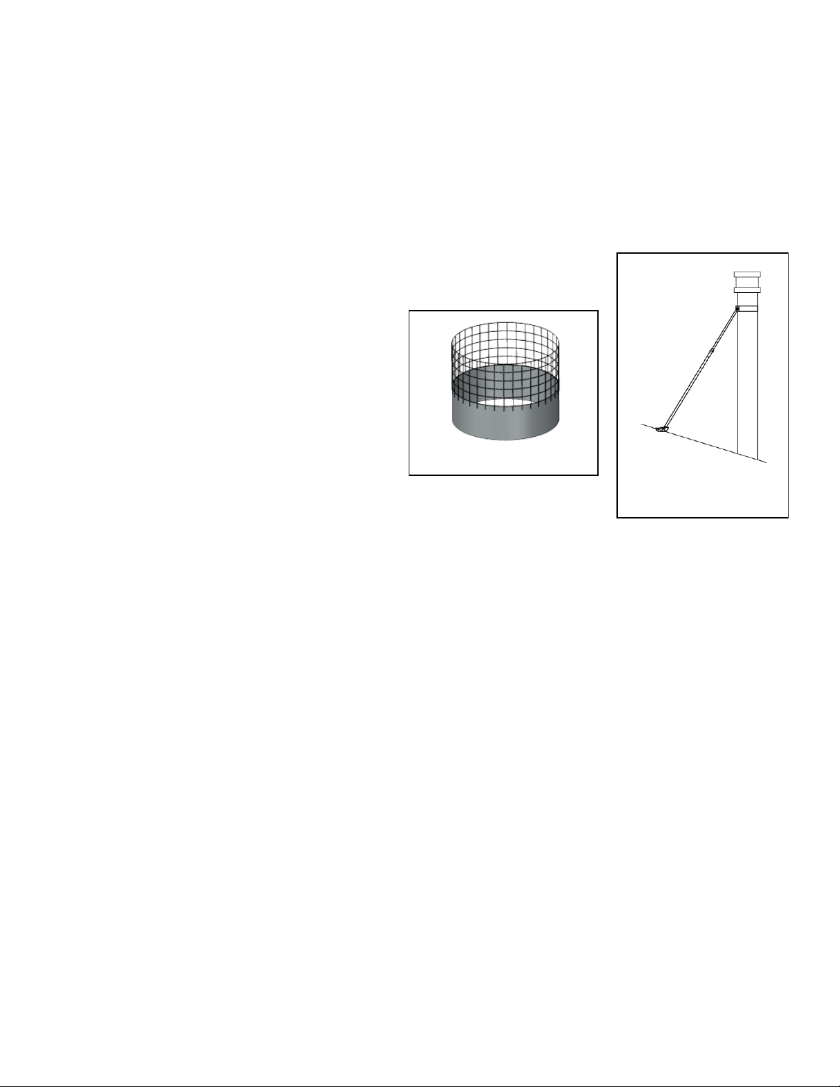
Spark Arrestor (SA)
The Spark Arrestor prevents floating embers from exiting the chimney while allowing flue gas to escape.
To Install (See Fig 27):
1. Open pivoting top on Rain Cap
2. Position the solid band of the Spark Arrestor down inside the flue. The wire mesh should be positioned upward.
3. Close top on Rain Cap
Telescopic Roof Brace (TRB)
The Telescopic Roof Brace provides lateral support for the chimney that extended above the roof line. The TRB must be installed every 5 ft. of
vertical chimney above the roof surface. No more than 5’ of chimney may extend beyond the roof brace.
To Install (See Fig 28.)
1. Attach Legs of the Roof Brace to the Band
2. Position the Band around the chimney.
3. Attach the mounting brackets to the Legs
4. Position the mounting brackets on the roof such that the Legs form approximately a 60° angle
between the legs and the chimney
5. Secure Mounting Brackets to the Roof surface.
6. Tighten all hardware nuts & bolts.
Final Check
Before completing assembly, recheck all joints to ensure the locking band has been properly installed and has
captured the bead. Confirm all clearances and support spacing is correct. Remove any protective film or
packaging materials from chimney components.
Important Notice
The UL listing for this product is void if components other than the Listed Components are used. All warranties, stated or implied, are void if the vent
or appliance is installed in a non-conforming manner.
Operation & Maintenance
The method and materials burned in your appliance directly affects the formation of creosote & soot. Burn only seasoned firewood. Avoid burning
green or unseasoned wood. Follow the appliance manufacturers owner’s manual for instructions on how to operate the appliance, start and build a
fire.
When wood is burned slowly, it produces tar and other organic vapors, which combine with expelled moisture to form creosote. The creosote vapors
condense in the relatively cool chimney flue of a slow-burning fire. As a result, creosote residue accumulates on the flue lining. When ignited this
creosote makes an extremely hot fire. The chimney should be inspected once every 2 months during the heating season to determine if a creosote
or soot buildup has occurred. If creosote or soot has accumulated, it should be removed to reduce the risk of chimney fire.
Fig 27. Spark Arrestor
Fig 28. Telescopic Roof
Brace
14
Jeremias INSTALL_HT Rev: 3/26/19
Fig 30. TEE SUPPORT INSTALLATION
Fig 29. CEILING SUPPORT INSTALLATION

15
Jeremias INSTALL_HT Rev: 3/26/19
Jeremias 25 Year Warranty
I. 1-Year Limited Warranty
Jeremias Inc. (“Jeremias”) provides a 1-year limited warranty (“1-Year Limited Warranty”) for its UL-103 HT Chimneys, all variations of Model HT
(collectively, the “Products”) for any defect in workmanship or materials under normal use from the date of shipment to the purchaser of Products
(“Purchaser”), subject to the following conditions:
•Product sizing and specifications have been performed in accordance with generally accepted engineering practices.
•Correct installation and maintenance in full compliance with Jeremias’ installation and maintenance instructions as published at the time of
installation.
II. Extended 25-Year Limited Warranty
Jeremias provides for an extended 25-year limited warranty (“25-Year Limited Warranty”) for any defect in workmanship or materials under normal use
(excluding termination caps) from the date of shipment to the Purchaser, transferable to subsequent purchasers of the home or building during the
described term of the warranty and subject to the satisfaction of the following conditions:
•Product will be installed by a chimney or venting professional familiar with standard chimney practice, fire codes and the Jeremias installation
instructions or an inspector authorized by Jeremias, that the Product assembly and installation conformed to all of Jeremias’ assembly and
installation instructions.
•Products were at all times operated and maintained in full compliance with Jeremias’ operation and maintenance instructions as published at the
time of installation or as later provided to Purchaser by Jeremias.
III. Exclusion of Limited Warranty
The 1-Year Limited Warranty and the 25-Year Limited Warranty (collectively the “Limited Warranty”) shall not cover (i) Product deviations which do
not effect functionality; or (ii) damages caused by: contamination of ambient air or combustion air by chlorinated hydrocarbons or other vapors which
may cause excessively severe acid condensate to form within the Products; merchandise provided by other manufacturers; installation, transport or
start up; Purchaser, and installer or other third parties; normal wear and tear; any party other than Jeremias in a willful manner; force majeure, including,
but not limited to flood, fire or frost; non-compliance with the assembly, installation, operation and maintenance instructions available at
www.JeremiasInc.com; assembly, installation, maintenance or repair by unqualified personnel; improper start up; use of Products not in accordance
with their intended purpose; exposure of Products to any metals of an inferior quality; contamination of the Products between unpacking and assembly;
burning of wood other than unpainted, natural wood, which has been stored for at least 3 years and which moisture level does not exceed 20%; or
burning of chipboard or domestic waste.
IV. Remedies
If a valid Limited Warranty claim arises, Jeremias shall, it its sole discretion, either repair the Product or deliver a properly functioning Product. This
Limited Warranty is limited to repair or replacement of the Product plus shipping cost to the location of the defective Product. The Limited Warranty
does not cover labor costs for removal or replacement of the defective Product, unless such labor shall be carried out by Jeremias itself in its sole
discretion.
V. Filing of a Limited Warranty Claim
Limited Warranty claims may only be asserted during the term of the applicable Limited Warranty period. Any extension of the term of the Limited
Warranties shall be excluded, regardless of the legal basis. If Purchaser believes that there is a justified Limited Warranty claim, Purchaser shall notify
Jeremias to that effect in writing. Any claims stemming from or relating to a Limited Warranty shall be asserted in detail within eight weeks after the
discovery of the defect (the time when the notification is received by Jeremias will be the basis for determining whether a claim has been reported
within this deadline) or else shall be excluded and not be recognized by Purchaser. Such notification shall include a description of the defect, original
proof of purchase, and a copy of the written inspection report as described in Section II above (if applicable).
VI. No Other Warranty
EXCEPT AS SET FORTH EXPRESSLY THEREIN, JEREMIAS MAKES NO WARRANTIES, EITHER EXPRESS OR IMPLIED, REGARDING THE
PRODUCTS, INCLUDING, BUT NOT LIMITED TO, THE IMPLIED WARRANTIES OF MERCHANTABILITY AND FITNESS FOR A PARTICULAR
PURPOSE.
VII. Damages Disclaimer and Limitation
IN NO EVENT SHALL JEREMIAS BE LIABLE TO ANY CLIENT OR ANY OTHER PERSON FOR ANY (A) INDIRECT, INCIDENTAL,
CONSEQUENTIAL OR PUNITIVE DAMAGES, INCLUDING LOSS OF PROFIT OR GOODWILL OR (B) DIRECT DAMAGES TO BODY, HEALTH OR
PROPERTY FOR ANY MATTER ARISING OUT OF OR RELATING TO THE PRODUCTS, WHETHER SUCH LIABILITY IS ASSERTED ON THE
BASIS OF CONTRACT, TORT OR OTHERWISE EVEN IF JEREMIAS HAS BEEN ADVISED OF THE POSSIBILITY OF SUCH DAMAGES. IN NO
EVENT SHALL JEREMIAS’ TOTAL AGGREGATE LIABILITY FOR DAMAGES EXCEED THE GREATER OF THE AMOUNT OF (A) TOTAL
COMPENSATION PAID BY PURCHASER TO JEREMIAS FOR THE PRODUCTS, OR (B) PROCEEDS AVAILABLE FROM ANY INSURANCE
POLICY IN EFFECT AND APPLICABLE TO THE EVENT GIVING RISE TO SUCH LIABILITY.
VIII. Notice
Any notice or other communication hereunder to Jeremias shall be sent postage prepaid, by certified mail, by courier such as United Parcel Service
or e-mail, to the following: Jeremias Inc., 983 Industrial Park Drive, Marietta, GA 30062, E-mail: Info@JeremiasInc.com. Notices shall be effective
upon receipt.
IX. Terms and Conditions of Sale
Purchaser’s Terms and Conditions of Sale as currently in effect shall govern these Limited Warranties, including without limitation the rights and
responsibilities granted hereunder.

16
Jeremias INSTALL_HT Rev: 3/26/19
Table of contents
Popular Ventilation Hood manuals by other brands


Fisher & Paykel
Fisher & Paykel HCB36-12 INSTALLATION GUIDE/USER GUIDE

GE
GE PVB98STSS installation instructions

Miele
Miele DA 399 OPERATING AND INSTALLATION Manual

KitchenAid
KitchenAid KVWC956KSS quick start guide

THOMSON
THOMSON DTT61XD - Instructions for installation and use

Viessmann
Viessmann FDVS-4 installation instructions


