Jesmay Electronics JM2280R User manual
2.4GHz WIRELESS AV LINK
OWNER’S MANUAL
(
((
(PLEASE READ BEFORE USE)
))
)
PLEASE CONSULT THE BACK COVER OF THIS
OWNER’S MANUAL FOR MODEL AND FEATURE
0336 !
■
■■
■Important-Safety Precautions
This device of which operation is subject to the following two condition
(1) This device may not cause harmful interference, and
(2) This device must accept any interference received, including interference
that may cause undesired operation.
•To prevent fire or shock hazard, do not expose this device to rain or moisture.
Do not use near a bathtub, washbowl, kitchen sink, or laundry tub, in a wet
basement, or near a swimming pool.
•To avoid electrical shock, do not open this device.
•This device should be operated to use only the power supply included with it
or provided as an accessory.
•Do not overload wall outlets and extension cords as this can result in the risk
of fire or electrical shock.
•Do not attempt to service this device yourself. Refer servicing to qualified
personnel only.
Caution: Changes or modifications not expressly approved by the
Party responsible for compliance could void the user’s authority to
operate the equipment.
■
■■
■Note:
This equipment has been tested and found to comply with the limits for a
class B digital device, pursuant to Part 15 of the FCC Rules, or BZT and
CE EMC directive. These limits are designed to provide reasonable
protection against harmful interference in a residential installation. This
equipment generates, uses and can radiate radio frequency energy, if not
installed and used in accordance with the instruction, it may cause harmful
interference to radio communications. However, there is no guarantee that
interference will not occur in a particular installation. If this equipment
does cause harmful interference to radio or television reception, which can
be determined by turning the equipment off and on, the user is encouraged
to try to correct the interference by one or more of the following measures:
•Reorient or relocate the receiving antenna.
•Increase the separation between the equipment and receiver.
•Connect the equipment into an outlet on a circuit different from
that to which the receiver is connected.
•Consult the dealer or an experienced radio/TV technician for help.
1
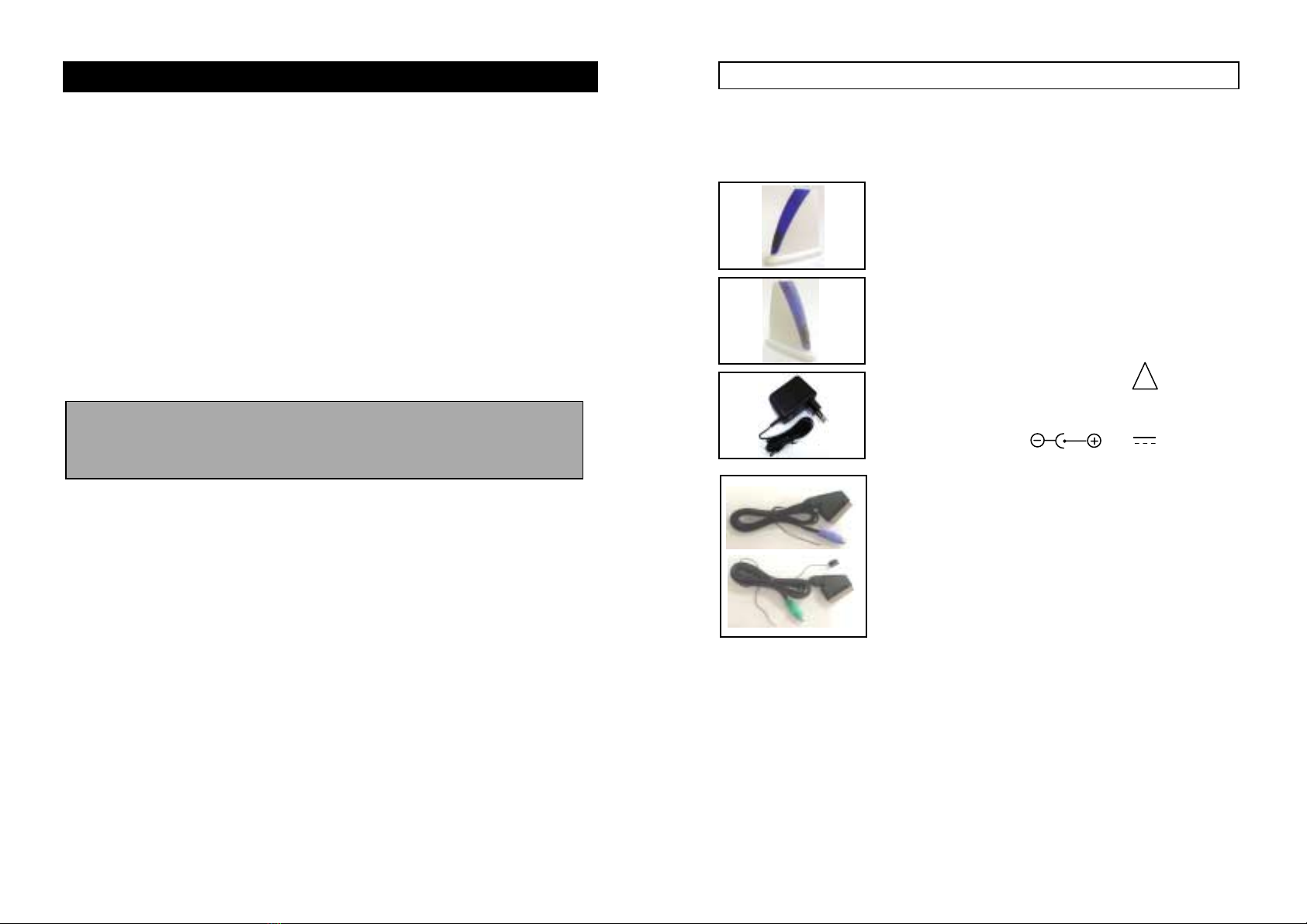
A. Checking Contents of Box
Checks to make sure that all of the items shown as below are included
with your 2.4 GHz Wireless Video Sender System. If something is missing,
please contact your dealer as soon as possible.
1. Transmitter ×1
2280T
2. Receiver ×1
2280R
3. Power adapter (optional) !×2
□(230VAC to 9VDC) or
□(120VAC to 9VDC)
DC in Jack ( 9V 300mA)
4. Cable
□MINI DIN to SCART connector A/V cable
(purple) ×1
□MINI DIN to SCART connector A/V cable
(green) ×1
(One for transmitter, One for receiver)
5. Owner’s manual ×1
2

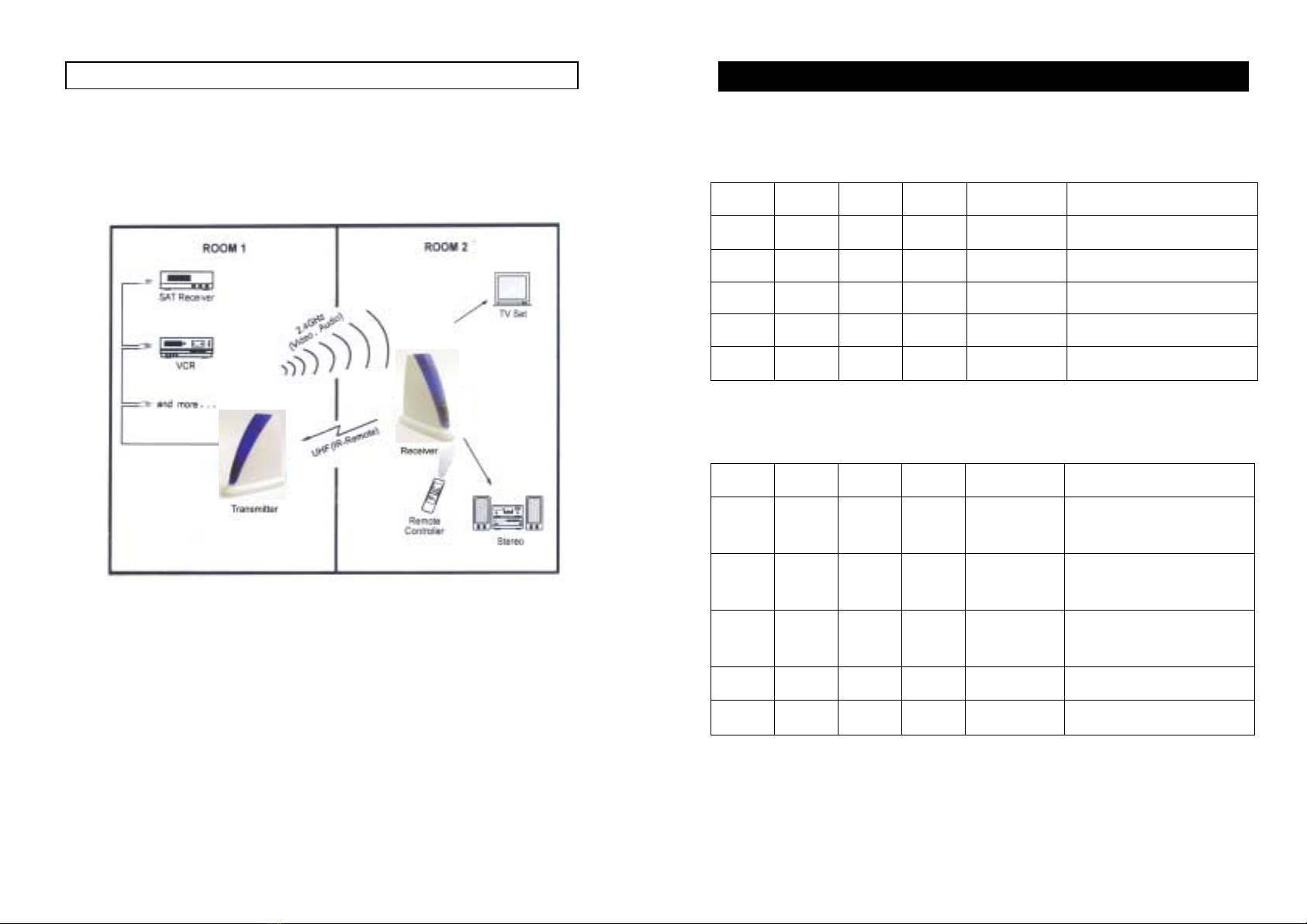
B. Introduction to 2.4GHz Wireless AV Link
This sender system is a wireless audio/video sender that uses advanced wireless
communication technology to deliver consistently sharp audio and video up to
100 meters away. By transmitting at a very high frequency (2.4 GHz), it avoids
the crowded 900 MHz band used by many cordless telephones and other
wireless audio/video transmitters. It’s superior quality is due to wide-band FM
rather than AM signal modulation.
It also integrates an UHF remote control extender to allow you to control the
audio or video source from another room using your existing remote controller.
Using sender system, you can enjoy greater convenience and security in many
ways:
General Application
•Watch the movie you rent on any TV in house without moving your VCR,
laser disc player or running messy cables.
•Watch cable or satellite programs on any TV in house.
•Listen to stereo-quality music from your receiver on any powered speakers
inside or outside the house.
•Uses multi-receivers for broadcasting to numerous TV sets in other rooms.
•Show computer images on a remote TV. (Additional equipment required)
Safety & Security Application:
•Applies as a wireless security system.
•Monitor your sleeping baby, playing children, the elderly, or the disabled
on TV using your existing camcorder.
•See who is outside the door on TV through your camera or miniature
CCD camera.
•Monitors and records meeting from another room.
•And many more uses!
3
■
The Using Attention
1. The outlet of the power supply must have the same voltage as the local area.
2. Be sure the transmitter and the receiver were connected to the equipment
Correctly (e.g. Connect the transmitter to the VCR, and the receiver to the
TV).
3. When switch is off from transmitter or receiver, it needs to wait for a few
seconds in order to restart again.
4. When two equipment or more is used at the same time, used different
channels. But a transmitter can be used with several receivers at the same
time.
5. When the equipment is operating, please do not use a microwave oven
near by.
6. The remote controller should face to the receiver IR remote control window,
and the transmitter IR extender should face to the source A/V equipment.
The IR remote has to be within the standard distance.
4

DC power input, connect
to power adapter (9VDC)
DC power input, connect
to power adapter (9VDC)
C. Product Layout
The following illustrations show the names of each component,
button and switch connectors on the transmitter and receiver.
FRONT VIEW FOR RECEIVER
LED
5
REAR VIEW FOR TRANSMITTER
Channel REAR VIEW FOR RECEIVER
CH4 (NTSC only)
RF output to TV
(e.g.2058R)
6
Power on/off switch
Channel
Switch
MINI DIN AV Jack
Power on/off switch
Channel
Switch
MINI DIN AV Jack
IR remote
control window
D. Setting Up 2.4GHz wireless AV Link
To enjoy wireless video and audio, just connect the transmitter to
whatever audio/video source you want to enjoy from another location,
and connect the receiver to the TV, monitor or powered speakers in
that other location.
A/V link system is suggested to connect to following A/V equipment use:
Video sources:Audio sources:
iVCR iCompact Disk player or Changer
iCable set-top box (with A/V output) iStereo Receiver
iSatellite Receiver iCassette Deck
iLaser Disc Player
iCamcorder or Miniature CCD Camera
iDigital decoder
iDVD
7
Make sure the ON/OFF switch is in the c
cc
cOFF f
ff
fposition before connection.
■
■■
■How To select channel
Transmitter:
CH1 CH2 CH3 CH4 Channel LED
ON ON ON ON CH1 Long light
OFF ON ON ON CH2 Long light
OFF OFF ON ON CH3 Long light
OFF OFF OFF ON CH4 Long light
OFF OFF OFF OFF CH1 Long light
CH1 have the first priority.
Receiver:
CH1 CH2 CH3 CH4 Channel LED
ON ON ON ON
Circle scan
CH1~4 Circle flash CH1~4
OFF ON ON ON
Circle scan
CH2~4 Circle flash CH2~4
OFF OFF ON ON Circle scan
CH3~4 Circle flash CH3~4
OFF OFF OFF ON CH4 Long light
OFF OFF OFF OFF CH1 Long light
The LED long light when work in single channel, When two or more switches
on, it work in scanning mode, and the LED flash accordingly, switches can be
selected arbitrarily.
8

■How To Transmit Audio/Video from Your VCR
1. Connect VCR and transmitter using the provided “MINI DIN TO SCART
A/V CABLE” with green MINI DIN plug, plug SCART to VCR output
jack, MINI DIN to transmitter. Please follow the instruction figure below.
2. Plug one end of the power adapter into the back of the transmitter and the
other end into
any 230-volt wall outlet (or 120-volt), Use only the adapter provided.
3. If you VCR has only one set of A/V output jacks and you want to use it
with a nearby TV. Connect 75ohm RF coaxial cable from the modulator
signal OUT port on your VCR to the RF IN port on your TV. (Note: In
order to also view cable programs on that TV, connect your incoming cable
TV source to the IN port of the VCR.)
4. Locate and orient the transmitter according to the section of this manual
titled "Orienting Units for Optimum Performance"for best performance of
transmitter.
Units for Optimum Performance for best performance of transmitter.
9
■
■■
■How To Transmit MINI DIN from Your Satellite Receiver
You can transmit audio/video either directly from your satellite receiver, or by
connecting them to your VCR. To transmit directly from your satellite receiver,
follow the instructions below.
1. Connect satellite receiver and transmitter using the provided “MINI DIN
TO SCART A/V CABLE” with green MINI DIN plug, plug SCART to any SCART jack
of satellite receiver, MINI DIN to transmitter. Please follow the instruction figure below.
2. Plug one end of the power adapter into the back of the transmitter and the
other end into any 230-volt wall outlet (or 120-volt), Use only the adapter
provided.
3. If your satellite receiver or laser disc player has only one set of A/V output
jacks, in this case, please connect 75ohm RF coaxial cable from satellite
receiver's modulator output port to TV RF input terminal.
4..Locate and orient the transmitter according to the section of this manual
titled "Orienting Units for Optimum Performance" for best performance of
transmitter.
10
■
■■
■How To Receive Wireless Audio/Video Signals on Your TV
There are two ways to receiver wireless audio/video signals on your remote
TV (TV in another location such as in bedroom, kitchen).
·Connect the receiver directly to the remote TV.
·Connect the receiver to a VCR, which is then connected to the TV.
If your TV has picture-in-picture capabilities, you can view any image
transmitted by sender, such as your sleeping baby, in a small inset picture while
enjoying other programming on the rest of the screen. Consult the owner's
manual of your TV for instructions on using these capabilities.
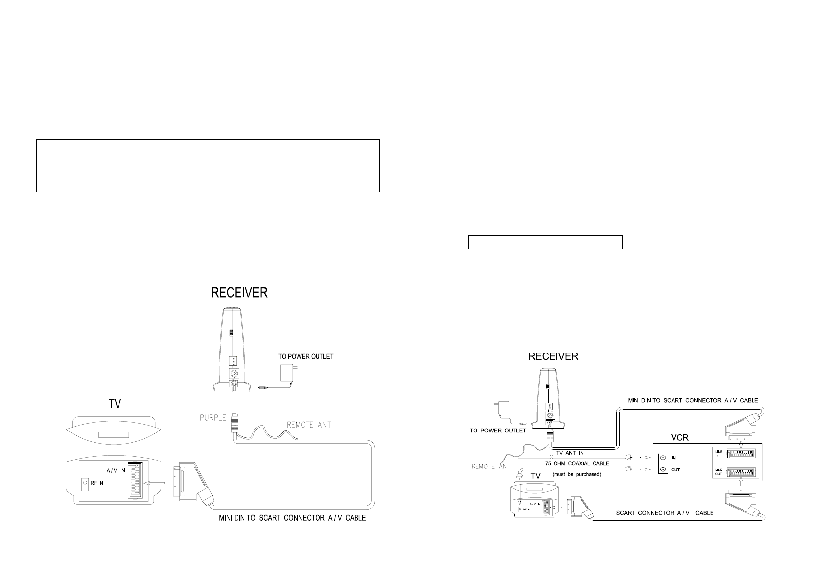
Connecting Receiver Directly to Remote TV
Connect TV and receiver using the provided “MINI DIN TO SCART A/V
CABLE” with purple MINI DIN plug, plug SCART TO TV, MINI DIN to
receiver. Please follow the instruction figure below.
11
■
■■
■Connecting Receiver to Remote TV through VCR
This setup enables you to record transmitted audio and video on your remote
VCR and also enjoy the picture and sound on a remote TV at the same time.
1. Connect VCR and receiver using the provided “MINI DIN TO SCART
A/V CABLE” with purple MINI DIN plug, plug SCART to the SCART input
of VCR, MINI DIN to receiver. Then connect TV and SCART output of VCR
using a “SCART to SCART A/V CABLE” (with must be purchased
additionally). Please follow the instruction figure below.
2. If your TV has A/V input jacks, connect another set of A/V cables to the
TV's A/V input jacks and to the A/V output jacks on your VCR.
3. If your TV does not have any A/V input jacks, please connect a 75ohm
coaxial cable from the TV's antenna in (or RF in) to VCR's modulator output.
This feature is optional
4. Plug one end of the sender power adapter into the back of the receiver and
the other end into any 230-volt (or 120 volt) wall outlet, DC in jack
9V/300mA. Use only the adapter provided.
5. Locate and orient the receiver to best video and sound quality please
according to the section of this manual titled "Orienting Units for optimum
Performance".
12
E. Orienting Units for Optimum Performance
This sender system should be placed on a flat, stable surface to prevent
damage to it from falling.
For optimum performance, both the audio/video and remote control antennas
should be carefully oriented as described below. In addition, to use the remote
extension feature, the transmitter itself must be specially oriented so it can relay
the converted remote control signal back to the audio/video source (see
following section titled "Using The Remote Control extension Feature"). For
maximum operating range, try to minimize the number of obstacles (e.g. your
TV or other electronics, large furniture) where between the transmitter and
receiver units.
THE AUDIO/VIDEO QUALITY ADJUST
Sender broadcast their high-quality audio and video using hidden omni-
directional antennas, only need to put the transmitter and receiver vertically and
make some adjustments, until picture and sound quality became perfect.
F. Using the Remote Control Feature
This sender system not only allows you to send crisp audio/video
from one area to another, it also gives you the ability to control the
source using your existing remote control device. It converts the
infrared (IR) signal emitted by your remote control to a radio
frequency (RF) signal in UHF band at the receiver and sends it back
to the transmitter where the RF signal is converted back to the
original IR signal and beamed to the audio/video source.
There is one way to get your source A/V equipment to be controlled
by using existing remote control through remote control feature:
There’s a IR output cable wiring of 2280T, put the IR end close to IR
receiving part of A/V source.
Sometimes, it may be difficult or even impossible to orient the
transmitter unit such that it can be "seen" (means face-to-face) by the
A/V equipment you wish to control. Perhaps there is no good surface
that allows for this or perhaps you wish to control. Or perhaps you
wish to remotely control A/V equipment in different locations
13
without re-orienting the transmitter. So, in this case, to use in
extender will be more convenient.
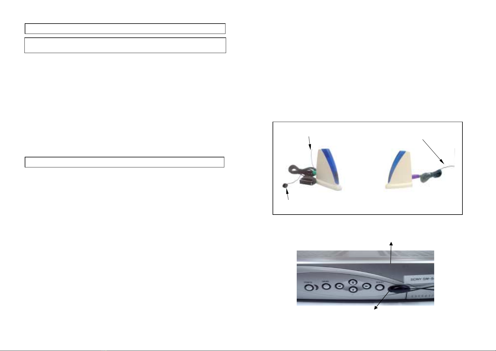
In order to obtain optimum performance of the remote control extender,
please operate as follow:
At the transmitter:Put IR Header near opposite to AV source IR receiver,
and keep remote antenna (outlet of A/V cable), in loose state with its end away
from cable.
At the receiver:
Direct remote control straightly against IR receiver in a distance of 5
meter, and keep remote antenna (outlet of A/V cable), in loose state with its
end away from cable.
Sketch map as follow:
TRANSMITTER RECEIVER
How to orienting the remote control antenna
DVD/VCR/SAT
Infrared receiver
14
Remote Control Antenna
IR Head
Remote Control Antenna

G. Troubleshooting, Care and maintenance
Please read this owner's manual carefully and follow the steps described in it. If
you still have difficulties, consult the following table. It will guide you though
the most common problems and their solutions.
Problem Possible solutions
No picture or sound
•Check all cable connections.
•Make sure power plugs are pushed all the way in.
•Check power switches on the remote TV and
Video source. (VCR, laser disc player, satellite
receiver, ect. )
•Check the power on/off switches on the
transmitter and receiver.
Interference:
Noisy picture or audio
•Adjust receiver and transmitter antenna orientation. ( see
section on "Orienting Units for Optimum Performance"
in this manual )
•Select a different channel by pushing the channel
selector button on both transmitter and receiver
so that the channels match.
•If using a microwave oven, turn it off.
•Remove microwave oven from path between
transmitter and receiver.
Remote control
extender does
not work
•Check the path between the transmitter and the
audio/video source and clear any obstructions.
•Check to see if the IR window on the bottom
front of the transmitter is blocked.
•Make sure IR extender is properly rotated in the
A/V equipment you wish to control.
•Adjust remote control antennas. (see section on
" Using the Remote Control Feature " in this manual )
Note: Clean the outside plastic packaging with a soft cloth lightly moistened
with mild soap and water. Never use any abrasive scouring powder
or solvent.
15
H. Specifications
Transmitter:
Operating Frequency Band 2.400GHz~2.4835GHz
Output Level 90 dBµV/m at 3 meters
Modulation FM (video and audio)
Video Input Level 1V p-p @75 ohm
Audio Input Level 1V p-p @600 ohm (STEREO)
Input Port MINI DIN 6PIN socket
Antenna Hidden omni-directional
IR–remote IR output 940nm with ON/OFF keying
Power consumption 9V DC, 300mA
Dimension 105mm×52mm×110mm
Weight 130g
Receiver:
Operating Frequency Band 2.400GHz~2.4835GHz
Noise Figure 3.5dB
Video Output Level 1V p-p @75 ohm
Audio Output Level 1V p-p @600 ohm (STEREO)
Output Port MINI DIN 6PIN socket
Antenna Hidden omni-directional
IR-remote Modulation ASK
Transmit Frequency 433.92 MHz
Infrared freq. Input 35 KHz ~41 KHz
Power consumption 9V DC, 300mA
Dimension 105mm×52mm×110mm
Weight 140 g
System:
Operational range up to 100 meter (line of sight)
Remote control range up to 50 meter (line of sight)
Operating temperature 10°C~50°C (14 F~122 F)
●All specification subject to change without notice
16
This manual suits for next models
1
Table of contents
Popular Transmitter manuals by other brands

Heathkit
Heathkit DX 35 Assembling and using

Allstar Products Group
Allstar Products Group MVP CKT-240 installation instructions

Zaxcom
Zaxcom ZMT3-FLEX user manual

Sennheiser
Sennheiser SI 434 operating instructions

Emerson
Emerson Rosemount 3051 Quick installation guide

Codem Music
Codem Music WiDMX by phone 2 user manual


Dakota Alert
Dakota Alert UT-3000 owner's manual

NIVELCO
NIVELCO NIVOPRESS DT 1 Series Installation and programming manual

Extron electronics
Extron electronics USB Extender Plus Series Setup guide

WIKA
WIKA N-10 operating instructions

Uniq Accesory
Uniq Accesory UniqCar user guide

Williams Sound
Williams Sound Hearing Helper T800 Specification sheet