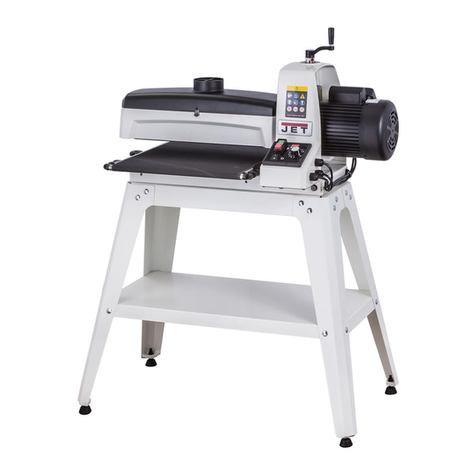
Jet JWDS-2244OSC-M User manual

JWDS‐2244OSC‐M OscillatingDrumSander
Zylinderschleifmaschine
Ponceuseàcylindreoscillant
Original:
GB
OperatingInstructions
Translations:
D
Gebrauchsanleitung
F
Moded´emploi
TOOLFRANCESARL
9RuedesPyrénées,91090LISSES,France
www.jettools.com
M‐723544OSCKM2019‐06

2
CE‐ConformityDeclaration
CE‐Konformitätserklärung
DéclarationdeconformitéCE
Product/Produkt/Produit:
Drumsander/Zylinderschleifmaschine/Ponceuseàcylindre
JWDS‐2244OSC‐M
723544OSCK‐M
Brand/Marke/Marque:
JET
Manufacturer/Hersteller/Fabricant:
TOOLFRANCESARL
9RuedesPyrénées,91090LISSES,
France
Weherebydeclarethatthisproductcomplieswiththeregulations
Wirerklärenhiermit,dassdiesesProduktderfolgendenRichtlinieentspricht
Parlaprésente,nousdéclaronsqueceproduitcorrespondauxdirectivessuivantes
2006/42/EC
MachineryDirective/Maschinenrichtlinie/DirectiveMachines
2014/30/EU
Electromagneticcompatibility/elektromagnetischeVerträglichkeit/compatibilitéélectromagnétique
2011/65/EU
RoHSdirective/RoHS‐Richtlinie/DirectiveRoHS
designedinconsiderationofthestandards
undentsprechendfolgenderzusätzlicherNormenentwickeltwurde
etétédéveloppédanslerespectdesnormescomplémentairessuivantes
ENISO12100:2010
EN60204‐1:2006+A1:2009
EN61000‐6‐2:2005
EN61000‐6‐4:2007+A1:2011
ResponsiblefortheDocumentation/Dokumentations‐Verantwortung/ResponsabilitédeDocumentation:
HeadProduct‐Mgmt/LeiterProdukt‐Mgmt./Resp.deGestionsProduits
TOOLFRANCESARL
2019‐05‐24ChristopheSAINTSULPICE,GeneralManager
TOOLFRANCESARL
9RuedesPyrénées,91090LISSES,
France

3
GB‐ENGLISH
OperatingInstructions
DearCustomer,
ManythanksfortheconfidenceyouhaveshowninuswiththepurchaseofyournewJET‐machine.Thismanualhasbeen
preparedfortheownerandoperatorsofaJET JWDS‐2244OSC‐M oscillating drum sander to promote safety during
installation, operation and maintenance procedures. Please read and understand the information contained in these
operatinginstructionsandtheaccompanyingdocuments.Toobtainmaximumlifeandefficiencyfromyourmachine,and
tousethemachinesafely,readthismanualthoroughlyandfollowinstructionscarefully.
TableofContents
Section Page
1.Declarationofconformity.............................................................................................................................................4
2.Warranty.......................................................................................................................................................................4
3.Safety...........................................................................................................................................................................4
3.1Authorizeduse..........................................................................................................................................................4
3.2Generalsafetynotes.................................................................................................................................................4
3.3Remaininghazards....................................................................................................................................................5
3.4Labelsandpositions..................................................................................................................................................5
4.0Specifications.............................................................................................................................................................6
5.0FeaturesandTerminology.........................................................................................................................................7
6.0Setupandassembly...................................................................................................................................................8
6.1Shippingcontents.....................................................................................................................................................8
6.2Toolsrequiredforassembly.....................................................................................................................................8
6.3Assemblingstand......................................................................................................................................................9
6.4Mountingsandertostand........................................................................................................................................9
6.5Handleandhosehanger...........................................................................................................................................9
6.6Infeedandoutfeedtables(optionalaccessory).......................................................................................................9
6.7Dustcollection........................................................................................................................................................10
6.8Installingabrasives..................................................................................................................................................10
7.0Electricalconnections..............................................................................................................................................11
8.0Adjustments.............................................................................................................................................................11
8.1DrumHeightControl...............................................................................................................................................11
8.2Depthscale.............................................................................................................................................................11
8.3Infeed/Outfeedtableadjustment(Optional).........................................................................................................11
8.4Conveyorbelttension/tracking..............................................................................................................................11
8.5Inspectingdrumalignment.....................................................................................................................................12
8.6Tensionrolleradjustment.......................................................................................................................................13
9.0Operations...............................................................................................................................................................13
9.1Drumandconveyormotoroperation.....................................................................................................................14
9.2Oscillatingmode.....................................................................................................................................................14
9.3BasicOperatingProcedure.....................................................................................................................................14
9.4Settingdepthofcut................................................................................................................................................14
9.5Establishingdrumheight........................................................................................................................................14
9.6SelectingSandSmart™feedrates...........................................................................................................................14
9.7Maximumperformancetips...................................................................................................................................15
10.0User‐maintenance.................................................................................................................................................16
10.1Cleaningandlubrication.......................................................................................................................................16
10.2Drummaintenance...............................................................................................................................................17
10.3Conveyorbeltreplacement..................................................................................................................................17
10.4Commutatorbrushinspection..............................................................................................................................17
10.5Additionalservicing..............................................................................................................................................18
11.0Trackerkit..............................................................................................................................................................18
12.0Abrasives................................................................................................................................................................19
12.1Selectingdrumabrasives......................................................................................................................................19
12.2Cleaningabrasivestrips........................................................................................................................................19
12.3Increasingabrasivelife.........................................................................................................................................19
12.4Abrasiveselectionguide.......................................................................................................................................19
13.0Troubleshooting.....................................................................................................................................................20
14.0Optionalaccessories..............................................................................................................................................21

4
1.Declarationofconformity
Onourownresponsibilityweherebydeclarethatthis
productcomplieswiththeregulationslistedonpage
2.Designedinconsiderationwiththestandards.
2.Warranty
TOOL France SARL guarantees that the supplied
product(s) is/are free from material defects and
manufacturingfaults.
Thiswarrantydoesnotcoveranydefectswhichare
caused,eitherdirectlyorindirectly,byincorrectuse,
carelessness, damage due to accidents, repairs or
inadequate maintenance or cleaning as well as
normalwearandtear.
Furtherdetailsonwarranty(e.g.warrantyperiod)can
befoundintheGeneralTermsandConditions(GTC)
thatareanintegralpartofthecontract.
TheseGTCmaybeviewedonthewebsiteofyour
dealerorsenttoyouuponrequest.
TOOLFranceSARLreservestherighttomakechanges
totheproductandaccessoriesatanytime.
3.Safety
3.1Authorizeduse
Thisdrumsanderisdesignedforsandingwoodand
similar materials only. Sanding of other materials is
not permitted and may be carried out in specific
casesonlyafterconsultingwiththemanufacturer.
Themachineisnotsuitableforwetsanding.
The proper use also includes compliance with the
operatingand maintenance instructions giveninthis
manual.
The machine must be operated only by persons
familiarwithitsoperationandmaintenanceandwho
arefamiliarwithitshazards.
Therequiredminimumagemustbeobserved.
The machine must only be used in a technically
perfectcondition.
Whenworkingonthemachine,allsafetymechanisms
andcoversmustbemounted.
In addition to the safety requirements contained in
these operating instructions and your country’s
applicable regulations, you should observe the
generally recognized technical rules concerning the
operationofwoodworkingmachines.
Any other use exceeds authorization.
Intheeventofunauthorizeduseofthemachine,the
manufacturer renounces all liability and the
responsibility is transferred exclusively to the
operator.
3.2Generalsafetynotes
Woodworking machines can be dangerous if not used
properly. Therefore the appropriate general technical
rulesaswellasthefollowingnotesmustbeobserved.
Read and understand the entire instruction manual
beforeattemptingassemblyoroperation.
Keep this operating instruction close by the machine,
protectedfromdirtandhumidity,andpassitovertothe
newownerifyoupartwiththetool.
Nochangestothemachinemaybemade.
Daily inspect the function and existence of the safety
appliances before you start the machine.
Donotattemptoperationinthiscase,protectthe
machinebyunpluggingthepowercord.
Before operating the machine, remove tie, rings,
watches,other jewellery, androllup sleevesabovethe
elbows.Removealllooseclothingandconfinelonghair.
Wearsafetyshoes;neverwearleisureshoesorsandals.
Alwaysweartheapprovedworkingoutfit:
‐ eyeprotection
‐ expiratoryprotection
‐ dustprotection
Donotwearlooseclothesandgloveswhileoperating
thismachine.
Install the machine so that there is sufficient space for
safeoperationandworkpiecehandling.
Keepworkareawelllighted.
Themachineisdesignedtooperateinclosedroomsand
mustbeboltedstableonfirmandlevelledtablesurface
oronthesuppliedcabinetstand.
Make sure that the power cord does not impede work
and cause people to trip. Keep the floor around the
machinecleanandfreeofscrapmaterial,oilandgrease.
Stayalert!Giveyourworkundividedattention.
Usecommonsense. Donotoperatethe machinewhen
youaretired.

5
Keepan ergonomic bodyposition. Maintain a balanced
stanceatalltimes.
Do not operate the machine under the influence of
drugs, alcohol or any medication. Be aware that
medicationcanchangeyourbehaviour.
Never reach into the machine while it is operating or
runningdown.
Alwaysclosethedrumcoverbeforeyoustartthe
machine.
Keepyourhandsdistanttodrumhousingandconveyor
beltwhenfeedingtheworkpiece.
Keepchildrenandvisitorsasafedistancefromthework
area.
Neverleavearunningmachineunattended.Beforeyou
leavetheworkplaceswitchoffthemachine.
Donotoperatetheelectrictoolnearinflammableliquids
orgases.Observethefirefightingandfirealertoptions,
forexamplethefireextinguisheroperationandplace.
Donotusethemachineinadumpenvironmentanddo
notexposeittorain.
Sandingdustisexplosiveandcanalsorepresentariskto
health.Alwaysuseasuitabledustextractiondevice.
Before machining, remove any nails and other foreign
bodiesfromtheworkpiece.
Workonlywithwellsharpenedtools.
Machineonlystockwhichrestssecurelyonthetable.
Always close the chuck cover before you start the
machine.
Specificationsregarding themaximumor minimumsize
oftheworkpiecemustbeobserved.
Do not remove chips and workpiece parts until the
machineisatastandstill.
Donotstandonthemachine.
Connectionandrepairworkontheelectricalinstallation
maybecarriedoutbyaqualifiedelectricianonly.
Haveadamagedorwornpowercordreplaced
immediately.
Makeallmachineadjustmentsormaintenancewiththe
machineunpluggedfromthepowersource.
Protectthe environment,
disposeofthepackingin
anenvironmentallyfriendlymanner.
Yourappliancecontainsvaluablematerialswhichcan
be recovered or recycled. Please leave it at a
specializedinstitution.
This symbol indicates separate collection for electrical
and electronic equipment required under the WEEE
Directive (Directive 2012/19/EC) and is effective only
withintheEuropeanUnion.
3.3Remaininghazards
When using the machine according to regulations
someremaininghazardsmaystillexist.
Themovingsandingsleevecancauseinjury.
Risk of kickback. The workpiece is caught by the
movingsandingsleeveandthrownbacktothe
operator.
Thrownworkpiecepartscanleadtoinjury.
Sandingdustandnoisecanbehealthhazards.Besure
towearpersonalprotectiongearsuchassafety
goggles and dust mask. Use a suitable dust exhaust
system.
Defectivesandingabrasivescancauseinjuries.
The use of incorrect mains supply or a damaged
powercordcanleadtoinjuriescausedbyelectricity.
3.4Labelsandpositions
A:Safetywarning
B:Sandingdrum&Conveyorbeltrunningdirection
C:Loosentablelockbeforeadjustingtableparallel
Fig.AFig.B
Fig.C

6
4.0Specifications
Modelnumber.............................................................................................................................................JWDS‐2244OSC‐M
Stocknumbers:
Sanderwithclosedstand...........................................................................................................................723544OSCK‐M
Closedstandonly................................................................................................................(providedstandard)723544CS
Foldinginfeed/outfeedtables.................................................................................................................723551(optional)
Digitalreadout.........................................................................................................................................723552(optional)
Motorandelectricals:
Drummotor:
Motortype……………………………………………..................................................................................................inductionmotor
Outputpower............................................................................................................................................1.3kW(1.75HP)
Voltage.......................................................................................................................................................~230V,PE,50Hz
ListedFLA(fullloadamps)...........................................................................................................................................9.5A
Motorspeed........................................................................................................................................................1400/min
Startingamps...............................................................................................................................................................28A
Runningamps(noload)..............................................................................................................................................4.3A
Startcapacitor..............................................................................................................................................300µF125VAC
Runningcapacitor..........................................................................................................................................20µF300VAC
Conveyormotor:
Motortype.................................................................................................................................totallyenclosedDCmotor
Horsepower.................................................................................................................................................................40W
Motorspeed............................................................................................................................................................54/min
Oscillatingmotor:
Motortype.................................................................................................................................totallyenclosedDCmotor
Horsepower.................................................................................................................................................................40W
Motorspeed..........................................................................................................................................................120/min
PowerSwitch.............................................................................................................................................magneticswitch
Powercord.........................................................................................................................H05RN‐F,3x1.0mm2,1830mm
Recommendedcircuitandfuse/breakersize1.............................................................................................................16A
Soundemission2...............................................................................................................68dBidling;70dBinoperation
AcousticpressurelevelLpA(ENISO11202)
Capacities:
Maximumboardwidth(singlepass)......................................................................................................................560mm
Maximumboardwidth(twopasses)....................................................................................................................1120mm
Maximumboardthickness.....................................................................................................................................102mm
Minimumboardlength............................................................................................................................................60mm
Minimumboardthickness3....................................................................................................................................0.8mm
Mainmaterials:
Closedstand.................................................................................................................................................................steel
Drum....................................................................................................................................................extrudedaluminum
Extensiontables(optional)...........................................................................................................................................steel
Conveyortable.............................................................................................................................................................steel
Drumheightadjustmenthandle.......................................................................................................aluminumandplastic
Sandingdrum:
Drumdimension.....................................................................................................................................dia.127x584mm
Drumspeed.........................................................................................................................................................1400/min
Oscillatingfrequency...........................................................................................................infinitelyvariable,0‐120/min
Oscillatingstroke......................................................................................................................................................19mm
Sandingpaperinstalled.............................................................................................................................................80grit
Drumelevationperonerotationofhandwheel.....................................................................................................1.6mm
1Subjecttolocal/nationalelectricalcodes.
2 The specified values are emission levels and are not necessarilytobeseenassafeoperatinglevels.Asworkplaceconditions vary, this
informationisintendedtoallowtheusertomakeabetterestimationofthehazardsandrisksinvolvedonly.
3Useofacarrierorbackerboard(notprovided)isrecommendedforcuts1.5mmorless.Seesect.9.3.

7
Conveyor:
Conveyorspeed……………………………………..............................................................................infinitelyvariable,0‐3m/min
Conveyortabledimensions…………………………….............................................................................................660x552mm
Conveyorheightfromfloor…………………………………………........................................................................................857mm
Dustcollection:
Dustportoutsidediameter....................................................................................................................................100mm
Minimumextractionvolumerequired.................................................................................................................560m3/h
Dimensions:
Shippingcarton,basemachine..............................................................................………………………..1320x700x718mm
Shippingcarton,closedstand.........................................................................…………………………………1030x508x770mm
Assembleddimensions……………………………………..............................................................................1200x610x1320mm
Weights:
Netweight...................................................................................................................................................................98kg
Shippingweight.........................................................................................................................................................131kg
Thespecificationsinthismanualwerecurrentattimeofpublication,butbecauseofourpolicyofcontinuousimprovement,
JETreservestherighttochangespecificationsatanytimeandwithoutpriornotice,withoutincurringobligations.
5.0FeaturesandTerminology
TheillustrationbelowshowsthemajorcomponentsandfeaturesoftheJWDS‐2244OSC‐MSander.Theseare
referencedthroughoutthemanualandwillhelptofamiliarizeyouwiththeoperationandfunctionsofthemachine.
Figure5‐1:featuresandterminology

8
Readandunderstandtheentire
contentsofthismanualbeforeattemptingset‐upor
operation!Failuretocomplymaycauseserious
injury.
NOTE:Figuresinthismanualmayshowoptional
accessories.Dependinguponyourmodel,thesemay
bepurchasedseparately.
6.0Setupandassembly
Openboxesandcheckforshippingdamage.Report
anydamageimmediatelytoyourdistributorand
shippingagent.Donotdiscardanyshippingmaterial
untiltheDrumSanderisassembledandrunning
properly.
Comparethecontentsofyourboxeswiththe
followingpartslisttomakesureallpartsareintact.
Anymissingpartsshouldbereportedtoyour
distributor.Readthisinstructionmanualthoroughly
forassembly,maintenanceandsafetyinstructions.
6.1Shippingcontents
Box#1:(seeFigure6‐1)
1 Sanderwithconveyortable(A)
1 Heightadjusthandle(B)
1 Hosehanger(C)
2 SocketheadscrewM6x12(C1)
2 Flatwasher6mm(C2)
1 Instructionmanual
1 Sparepartslist
Box#2:Infeedandoutfeedtables
(Optional,seeFigure6‐2)
2 Infeed/outfeedtables(D)
1 Rear(short)fixedbracket(E)
1 Front(long)fixedbracket(F)
2 Foldingtablebrackets(G,H)
1 Hardwarepackage,includes:
4 Lockinghandles(HP1)
4 Discwashers(HP2)
4 Bronzewashers(HP3)
16 SocketheadscrewsM8x16(HP4)
16 FlatwashersM8(HP5)
4 SocketheadscrewsM6x20(HP6)
4 FlatwashersM6(HP7)
4 Eccentriccams(HP8)
6.2Toolsrequiredforassembly
5mmand6mmhex(Allen)wrenches.
Straight edge (such as straight steel bar or carefully
jointedboard).
Figure6‐1:Sandercontents
Figure6‐2:Infeed/OutfeedTables(OPTIONAL)

9
Figure6‐3:AssemblyofSanderandOPTIONALInfeed/OutfeedTables
6.3Assemblingstand
A closed stand is provided standard with the JWDS‐
2244OSC‐M Sander. Refer to the assembly
instructionsthataccompanythestand.
6.4Mountingsandertostand
The closed stand can be oriented with storage door
towardsthefrontorbackofmachine.
1. Lift drum head assembly out of the box, and
temporarilyrestitcrosswiseontopofstand.
Use an assistant to help lift
thesander.
2. Positionsanderatopstandsothatthethreaded
holesofbasealignwithholesinthestand.
3. Fasten base to stand (from beneath) with the 6
provided screws and washers. Tighten screws
securely.
6.5Handleandhosehanger
1. Installheightadjustmenthandle(B,Fig6‐3)onto
spindleandtightensetscrew.
2. Raise drum and remove shipping block from
betweendrumandconveyor.
3. Installhosehanger(C)withscrewsandwashers
(C1/C2).
6.6 Infeed and outfeed tables (optional
accessory)
The sander must be bolted to the stand or a work
tablewhenusingthesetableextensions.Maximum
working load of each table is 16kg. Fasteners are
providedwiththeextensiontables.
1. Install infeed and outfeed brackets (F, E, Figure
6‐3) to the threaded holes in sander base with
socketheadscrewsandflatwashers(HP4/5).
Makesureleftandrightbracketsareorientedas
shown.Thebracketsshouldbeflushagainstthe
base. NOTE: Long brackets mount to front
(infeed);shortbracketstorear(outfeed).
2. Tightenscrews(HP4)
3. Install eccentric cam (HP8) with screw and
washer(HP6/7).Fingertightenonlyatthistime.
4. Install table brackets (G,H), using handles and
washers(HP1/2/3).
5. Placeextensiontables over brackets andsecure
with socket head screws and washers (HP4/5).
Fingertightenonly.
6. Position tables slightly below conveyor belt
surface for proper support of stock. To check
position, place a straight‐edge on one side of
conveyor table under drum and extending out
overtheextensiontable.

10
7. Lower drum to securely hold straight‐edge in
place.SeeFigure6‐4.Raiseinfeed/outfeedtable
untiltablesurfaceisslightlybelowconveyorbelt
surface.Tightenscrewsonthatside.
8. Reposition straight‐edge to other side of table
andrepeat.
9. Loosen screw (HP6) and rotate eccentric cam
(HP8)untilitcontactslipoftablebracket.Dothis
onbothsidesofinfeedtable.Thisensuresinfeed
tablewillremainlevelwithconveyor tableeach
timeitisreturnedtooperatingposition.Tighten
screws(HP6).
Ifstockbeingsandedisbowed,warpedorotherwise
inconsistent, be sure tables are lower than top of
conveyortable.
Ifstockslipsonconveyor,thetablesmaybe
positioned too high. Lower tables to allow stock to
remainincontactwithconveyor.
Figure6‐4:extensiontablealignment
6.7Dustcollection
Dustcollectionismandatoryforasafework
environmentandextendedabrasivelife.Themachine
is equipped with a 100mm dust collection port.
Securea100mmdustcollectionhosetotheportwith
a hose clamp (Figure 6‐5), and connect to a dust
collector(minimum560m3/h).
Figure6‐5(hoseandclampnotincluded)
6.8Installingabrasives
Properattachmentoftheabrasivestriptothedrum
iscriticaltoachievingtopperformancefromyour
drumsander.
An80‐grit,76mm wide abrasive strip is pre‐installed
onthedrum.
(TIP:Ifyouareusinganafter‐marketabrasive,usea
new JET‐supplied abrasive as a template to quickly
cutanewstrip.
Figure6‐6:abrasivetrimming
Toinstallabrasivestrip:
1. Press fastener lever (Figure 6‐7) on outboard
(left)endofdrum,andinserttaperedendof
abrasivethroughslitinfastener,asshown.Insert
approximately 75mm of abrasive strip into
fastener. Align tapered edge of abrasive strip
withleftedgeofdrum.
Figure6‐7
2. Releasefastenerlevertosecureendofstrip.
3. Begin wrapping abrasive around drum. The
taperededgeofstripendshouldfollowasclose
aspossibletoedgeofdrum.
4. Continue to wrap abrasive in spiral fashion by
rotating drum with one hand and guiding strip
withtheother.SeeFigure6‐8.
Successive windings of strip must not have any
overlap. They should be flush with previous
windingsorwithaslightgapbetween.

11
Figure6‐8
5. Press inboard take‐up lever (Figure 6‐9) and
insert trailing end of strip as far as it will go. If
necessary,trimtaperedendofabrasivestrip.
6. Releaseinboardtake‐uplevertosecurestrip.
All abrasive strips will stretch over time as they are
used, and may stretch enough to allow the take‐up
lever to reach its lowest position so that it cannot
maintaintensiononthestrip.Ifthisoccurs,followthe
aboveprocedurestoresetthetake‐uplever.
Figure6‐9
7.0Electricalconnections
Allelectricalconnectionsmustbe
donebyaqualifiedelectricianincompliancewithall
local codes and ordinances. Failure to comply may
resultinseriousinjury.
TheSanderisratedat230Vpower.Thesandercomes
withaplugdesignedforuseonacircuitwitha
groundedoutlet.
Itisrecommendedthatthesanderbeconnectedtoa
dedicated16ampcircuitwithcircuitbreakerorfuse.
Ifconnectedtoacircuitprotectedbyfuses,usetime
delayfusemarked“T”.Localcodestakeprecedence
overrecommendations.
8.0Adjustments
Disconnect sander from power
sourcebeforemakingadjustments.
8.1DrumHeightControl
Drum height and depth ofcutarecontrolledby
height adjustment handle (see Figure 5‐1). Rotating
handle clockwise lowers drum, counter‐clockwise
raises it. One revolution of handle will move drum
approximately1.6mm(or1/4turn=approx.0.4mm),
asshownonthelabelbelowhandle.
8.2Depthscale
The depth scale indicates distance between bottom
of sanding drum and top of conveyor belt.
Adjustmentisperformedby“zeroing”thescale.
1. Unplugsanderfrompowersource.
2. With an abrasive strip on drum, lower drum to
whereittouchestopofconveyorbelt.
3. Atthisdrumposition,thedepthscalepointer
shouldalignwithzeromarkonscale.Ifitdoes
not,loosentwoscrewsandraiseorlowerscale
untilzeroalignswiththepointer.
4. Retightenscrews.
Note:Dependingondesiredaccuracy,youmayneed
to repeat this process when installing different
abrasivegrits.
8.3 Infeed/Outfeed Table Adjustment
(OPTIONAL)
The optional tables can be swung down to allow
easieraccessforabrasivewrappingorother
adjustments.
Loosen handles on each side, slide table away from
machineandthendown.SeeFigure8‐2.
Figure8‐2

12
8.4Conveyorbelttension/tracking
Conveyor belt tension adjustment may be necessary
during the break‐in period to compensate for belt
stretching.
8.4.1Belttensionadjustment
1. Unplugsanderfrompowersource.
2. Adjusttake‐upscrew(Figure8‐3)with5mmhex
wrench. Do this on both sides of conveyor to
obtain approximately equal tension on both
sidesofsandingbeltwhentaut.
NOTE: Insufficient belt tension will cause
slippage of conveyor belt on drive roller during
sandingoperation.Theconveyorbeltistooloose
if it can be stopped by hand pressure applied
directly to top of moving conveyor belt.
Excessive belt tension can result in bent rollers,
bentbrackets,and/orprematurewearingof
bushingsorconveyorbelt.
Figure8‐3:belttensionadjustment
8.4.2Trackingadjustment
Abelttrackscorrectlywhenitmovescentrallyonthe
conveyor rollers without drifting to either side.
Trackingadjustmentsaremadewhileconveyorbeltis
running.
1. Unplugsanderfrompowersource.
2. Make sure proper belt tension has been
achieved(seesect.8.4.1).
3. Turnonconveyorandsettomaximumspeed.
Watch for tendency of conveyor belt to drift to
onesideofconveyor.Ifitdrifts,tightenorloosen
take‐upscrew.
Note: Adjust take‐up screw only 1/4 turn at a
time.Allowtimeforbelttoreacttoadjustments
beforeproceedingfurther.
Trytoavoidoveradjustments,asthismayaffect
belttension.Iftensionisaffected,ifmaybecome
necessary to use both take‐up screws to
accomplishtensioningandtracking.
8.4.3Trackers
Thesandercomesequippedwith“Trackers”,ceramic
guides that reduce the amount of adjustments
neededto keep conveyor belttracked(centered) on
conveyor table. These guides have a magnetic
backingtokeeptheminplace.IfaTrackerwears
through, it can be reversed by turning it over. See
sect.11.0TrackerKitformoreinformationaboutre‐
settingtrackers.
8.5Inspectingdrumalignment
Thesandingdrummustbeparalleltoconveyortable
for proper machine operation. The sanding drum
comes pre‐aligned from the manufacturer. If a
problem with drum alignment should occur, follow
theinstructionsbelow.
First,inspectthealignmentwithagaugeofsome
kind. The following procedure uses a steel straight‐
edgeasagauge.
1. Unplugsanderfrompowersource.
2. Opendustcoverandremoveabrasivestripfrom
drum.
3. Insertgaugebetweendrumandconveyortable
atoutboardsideofdrum(A,Figure8‐4).
Figure8‐4:drumalignment
4. Withdustcoveropen,lowersandingdrumwhile
slowlyrotating drumbyhand,untildrumlightly
contactsgauge.NOTE:Makesuredrumcontacts
gauge,notjustthetensionrollers.
5. Removegaugeandplaceunderdrumatinboard
side.
6. Ifdrumdoesnotcontactgaugeequallyonboth
endsofdrum,alignmentisneeded.
Toalignconveyortablewithdrum:
7. Loosenbothtablelockingscrews(B)
Loosen both table locks
beforeadjustingdrumalignment.
8. Turnknob(C)toraiseorloweroutboardendof
table.Followdirectionalmarksonlabel(+raises,
‐lowers).

13
9. Retightentablelockscrews(B).
8.5.1Fine‐tuningdrumalignment
Note:Thisisanoperationaltestforsandingboards
wider than the drum. Perform this procedure only
after you have become familiar with sander
operation.
Whensandingboardswiderthanthedrum,table
alignment is critical and table must be adjusted
exactly level to slightly lower on the outboard end.
This will prevent any ridges from developing in the
stock.Alwayscheckthisonapieceofscrapwood,as
follows,beforesandingtheworkpiece.
1. Run a piece of scrap wood approximately
150mm wide by 700mm to 1000mm long
through the sander sideways so that end of
boardextendspastoutboardsideofdrum.
2. Without changing drum height, rotate board
180°andsandthesameside.
3. If a ridge is visible where the drum overlaps,
loosenbothtablelocks(B,Figure8‐4)andlower
table at outboard end slightly by turning knob
(C).
4. Repeatthisprocess until the ridgeiseliminated
andentireboardissanded.
Note: Whensandingnarrowstock(560mmorless),
returnconveyortabletoparallelposition.Turnknob
oppositedirectionuntillocknut(D,Figure8‐4)is
contacted. The lock nut provides a positive stop for
tableparallelism.
8.6Tensionrolleradjustment
The infeed and outfeed rollers are tensioned to
provide downward pressure on the workpiece to
prevent slippage on the feed conveyor. Tension
rollershavebeensetbythemanufacturer,butshould
be inspected and may require adjustment as the
sanderreceivesuse.
Improperly adjusted tension
rollers(i.e.thosesettoohigh,renderingthemnon‐
functional) could allow kickback of pieces being
sanded.
You can increase or decrease tension of roller on
outboardsidebyinsertingscrewdriverthroughholes
inplate(Figure8‐5)andturningscrewsonthe
tensionrollerbrackets.Theplatecanberemovedfor
easieraccess.Thescrewsatinboardsideofdrumcan
beadjustedinsimilarmanner.
Figure8‐5:tensionadjustmentscrews
Toomuchtensionrollerpressurecanresultina
“snipe” mark, which is a visible line running across
the width of the board and located approximately
60mmfromendofboard.
If snipe occurs on the leading end of board, adjust
outfeedtensionroller.If the snipeoccurson trailing
endofboard,adjustinfeedtensionroller.
9.0Operations
Before using your drum sander, review the previous
sections on initial set‐up and adjustment. Before
operating,makesureanabrasivestripismounted
andaproperdustcollectionsystemisconnected.
9.1Drum&conveyormotoroperation
1. Connectpowersupplytomachine.
2. Disengage emergency stop by clockwise turning
theredbuttonorpullingitup(A,Figure9‐1).
Note: Error Indicator (D, Figure 9‐1) may flash
continuouslytoremindthattheconveyorspeeddial
is NOT set at OFF position before starting the
operation.Thecontrolsystemisdesignedtoprevent
theconveyor beltfrombeing activatingaccidentally.
Ifconveyorbeltmotordoesn’twork,turnthedial(C,
Figure9‐1)toOFFandre‐dial.
3. TurnontheOn/Offswitch(B)tostartdrum
motor.
4. Rotateconveyorspeeddial(C)clockwisetostart
andincreasespeedofconveyor.

14
Figure9‐1:controlpanel
9.2Oscillationmode
The sander can be used with sanding drum in fixed
positionorinoscillationmode.Thetopdial(Figure9‐
1,E)activatesoscillationmode.
NOTE:Ifchangingfromoscillationmodetofixed
mode, allow drum to center itself over conveyor
beforeturningoffoscillationmode.
9.3BasicOperatingProcedure
1. Establishdepthofcut.
2. Startdustcollectionsystem.
3. Startsandingdrum.
4. Startoscillationandselectspeed.
5. Startconveyorandselectfeedrate.
6. Feedstockthroughmachine.
Tofeedstockthroughthesander,restandholdboard
tobesandedonconveyorbelt,allowingconveyor
belttocarryboardintodrum.Oncestockishalfway
through, reposition yourself to outfeed side of
machinetoreceiveandcontrolboardasitexits.
Boardwillbeforceddownagainst
conveyortable asit beginsfeeding,causingpinching
hazard.Keepfingersaway.
Do not open drum hood until
drumcomestoacompletestop.
9.4Settingdepthofcut
Adjusting the drum sander for proper contact
betweenabrasiveandstockdeterminesthedepthof
cut.Thedepthofcutiscontrolledbytheheight
adjustmenthandle.
Itmaytakeexperimentationtodetermineproper
depthofcut,giventhevariablesofabrasivegrit,type
ofwoodandfeedrate.Forbestresults,usescrap
wood to practice sanding and to develop skill and
familiaritywiththemachinebeforedoingfinishwork.
A combination of several variables will determine
properdepthofcuttouse,includingthefollowing:
1. Abrasivetypeandgritsize.
2. Widthofpiecebeingprocessed.
3. Hardnessofpiece.
4. Feedrateofconveyorbelt.
NOTE:Theuseofacarrierorbackerboard(not
provided), is recommended for cuts 1,5mm or less.
Thisis a flatboard,usuallyofwoodorMDF,slightly
larger than the workpiece and of even thickness,
placedbeneaththeworkpieceasitisfedthroughthe
sander.Theworkpiecemaybeattachedtothecarrier
withrubbercement,carpenter’stapeorsomeother
easilyremovableadhesive.However,someoperators
use a rubber or textured surface on the carrier to
helpstabilizetheworkpiecebysimplefriction.
9.5Establishingdrumheight
A good rule of thumb when sanding with grits finer
than80:
1. To establish drum height, position stock under
thedrum.DoNOTstartdrum.
2. Lowerdrumtothestock thickness,makingsure
drum can still be rotated by hand while just
contactingstock.
Donotstartdrumwhilein
contactwithstock.
3. Withoutchangingdrumheight,turnonconveyor
andrunthestockoutfromunderthedrum.Start
sanding drum and sand stock at that same
position.
4. With the drum operating, feed stock under the
drum from the infeed side and against the
rotationofthedrum.Alwaysmaintaincontrolof
thestocktoavoidkickbackand/orslippage.
Forsandingwithgritscoarserthan80,youcanlower
thedrumslightly.
Always maintain control of stock. Through practice
youwilllearntheproperdepthofcutconsideringthe
variablesabove.
9.6SelectingSandSmart™feedrates
A faster feed rate allows faster sanding but fewer
revolutionsofthedrumperinchofsanding.Aslower
feedrateprovidesmorerevolutionsofthedrumper
inch of sanding to allow a greater depth of cut and
smoothsanding.
Beginexperimentingwith the feed ratesetat about
50%ofmaximum.Thebestfeedratewilldependona
number of factors, including type of stock, grit and
depth of cut used, and whether the stock is fed
directlyinlinewiththeconveyortableoratanangle.

15
Ifthedrummotorisluggingdown,ifconveyorbeltis
slipping,orifyouobservearippleeffectonthestock,
slow the feed rate. If the finish is smooth and the
machine is not overworking, you can experiment
usingafasterfeedrate.
The SandSmartTM controller continuously monitors
the load on the drum motor, and automatically
regulates the speed of the conveyor motor to
maintainthehighestfeedratewithoutoverload.
Whentheredindicatorlight(A,Figure9‐2)comeson,
the SandSmartTM control has detected too great a
depthofcutand/ortoofastafeedrate.
Iftheloadonthedrummotorincreases,the
SandSmartTMcontrolwilldecreasetheconveyorfeed
rate and will stop the conveyor under extreme
conditions. If the load on the drum decreases,
SandSmartTM will increase the feed rate but will not
increase it faster than the manual setting on the
speedadjustmentlabel.
Thebestandmostconsistentfinishwillbeachievedif
the conveyor does not change speed during
operation.
Figure9‐2:SandSmartTM
Achangeinconveyorspeedmayaffectthefinish
surface. If the finish is affected, make another
sandingpasswithoutchanginganysettings.
If the finish is still affected, make adjustments by
slowingtheconveyorand/ordecreasingthedepthof
cutandrunthestockthroughagain.
Alsotryafasterfeedrateorlessdepthofcutifthe
stock you are working begins to show burn marks.
Withcherry,hardmapleorotherhardwoods,usinga
shallowerdepthofcutandafasterfeedratewillhelp
minimizeburnmarks.Slightlyanglingthestockasitis
fed into the machine will also help prevent burning
thestock.
Becauseofthewiderangeofvariables,itisimportant
toexperimentwithyourspecificconditionsandmake
adjustmentstoachievetheoptimumfeedrate.If
problemsoccur,firstcheckandadjustthefeedrate,
referring to the “Troubleshooting” section in this
manual.
9.7Maximumperformancetips
Theversatility designedintothe drumsanderallows
ittobeusedforavarietyoftasksthatwillboost
returnonyourinvestment.Forexample,itwillspeed
up fine sanding work often done with slower, dust‐
generating hand sanders, and will achieve fine
thicknessadjustmentsnotpossibleonsomesanders.
Itcanbeusedtosurfacefiguredwoods–bird’seyeor
curlymaple,forexample–whichcanbedamagedif
fedthroughaplaner.
Learninghowtouseitsadjustmentsandcontrolswill
allow you to fine‐tune the machine for maximum
results. The best results come from experimenting
withdifferentabrasivegritsandmachineadjustments
tofitthejobathand.Followingisalistofusefultips
whichcanhelpyouimproveperformanceofyour
sander.
9.7.1Dustcollection
When connecting dust collectors, remember that
straight pipe will not restrict airflow as much as
flexibletubing.Y’sandelbowswillrestrictairflowless
thanT’s.Hosessmallerthan80mmdiametershould
notbeused.
9.7.2Multiple‐piecesandingruns
Whenabrasiveplaning(orthicknesssanding)arunof
similar pieces that you want to have the same
thickness,itisbesttodeterminethethicknessofthe
thinnest piece and process all pieces to that same
thickness in one session. Be aware that the sander
will remove cups and crowns in the workpiece;
considerthiswhenmeasuringandprocessingstockto
thesamethickness.
9.7.3Simultaneousmultiplepieces
When sanding multiple pieces simultaneously, make
sureto stagger(step) the piecesacross thewidth of
the conveyor belt. This provides better contact with
thetensionrollers.Trytoprocessonlymultiplepieces
ofsimilarthickness.
If there is a significant thickness difference, the
thinnerpiecescanslipontheconveyorbeltiftheydo
notcontactthetensionrollers.Alsonotethatpieces
thicker than 20mm should be longer than the
minimumnormallyrecommendedtopreventtipping
ofthestock.
9.7.4Edgesanding
When edge sanding, the sander will mimic the
opposite edge of the stock which is lying on the
conveyorbelt.Becauseofthis,itisimportantforthe
stockedgetohavebeenrippedattheproperangleto
the face before the sanding process. When edge
sanding stock that is less than 20mm wide or more
than 50mm high, it is good procedure to stack and

16
clampseveral pieces togethertoprevent themfrom
slippingortippingontheconveyorbelt.
9.7.5Sandingimperfectstock
When sanding stock with a cup or crown, place the
crownup.Thiswillstabilizethestocktohelpprevent
tippingorrockingduringsanding.Afterthecrownhas
beenremovedandthetopisflat,turnthestockover
andsandtheoppositeside.Toavoidpersonalinjury,
takespecialcarewhensandingstockthatistwisted,
bowed,or otherwise varies inthicknessfrom endto
end. If possible, support such stock as it is being
sandedtokeepitfromslippingortipping.Useextra
roller stands, help from another person, or hand
pressure on the stock, to minimize potentially
hazardoussituations.
9.7.6Faceframesandraisedpaneldoors
Itisveryimportanttohavetheproperabrasive
contact when doing this type of sanding. If the
machineissettotakeanexcessivedepthofcut,the
resultcanbeagougeordipasthedrumgoesfrom
sandingtherails atfull widthtosandingjustasmall
widthonthestiles.Topreventthismakesure,when
usingabrasivesfinerthan80grit,thatthedrumisin
contactwiththewoodbutcanstillbespunbyhand.
Ifthereisroom,anglingthestockontheconveyor
belt can also help. Slowing the conveyor feed when
comingtoarailinthestockcanhelppreventadipor
gouge.Thisallowstheabrasivetoworkthewider
width with less effort, and to achieve better
consistencyofthefinishedsurface.
9.7.7Stockfeedingangle
Some pieces, because of their dimensions, will need
tobefedintothemachineata90°angle
(perpendicular to drum). However, even a slight
offset angle of stock will provide for more effective
stock removal. The optimum feeding angle for stock
removalisabout60°.
Angling the workpiece for stock removal provides
other advantages, such as less loading of certain
areasofthedrumduetogluelinesormineralstreaks
inthestock,moreevenwearofabrasivestrips,
potentiallyfasterfeedrates,andlighterloadsonthe
motor.Notethattogetthebestfinalfinishhowever,
thestockshouldbefedthroughthemachinesoitwill
besandedinlinewiththegrainofthewoodonthe
finaloneortwopasses.
10.0User‐maintenance
Beforedoingmaintenanceonthe
machine, disconnect it from the electrical supply
(pull out the plug), unless indicated otherwise.
Failuretocomplymaycauseseriousinjury.
10.1Cleaningandlubrication
For best results, make cleaning the sander a regular
shopprocedure.Allowingexcessbuild‐upofdustand
debriscanadverselyaffectperformancethrough
loading of the abrasives, slippage on the conveyor
table,and/ortheaccumulationofmaterialinsidethe
drumswhichcanthrowoffthecenterofbalance.
NOTE: Bearings are pre‐sealed and require no
lubrication.
Brush the conveyor belt after cleaning
operations. If not cleaned, the conveyor belt
could allow stock to slip during sanding
operations.
Lubricate conveyor bushings as needed, and
checkforwear.
Lubricateelevatingleadscrew(A,Figure10‐1)as
needed.
Cleansawdustfromabrasivestripandbrushdust
fromconveyorbelt.
Keepslideareasclean(B,Figure10‐1).
Insert bearing grease (NLGI #2, DIN 51818) into
the five fittings (C, Figure 10‐2) every 150 work
hours.Donotover‐grease.
Blowdustfrommotorsandswitches.
Blow dust from inside of sanding drum, which
may cause vibration or offset the center of
balance. (Leave your dust collector on when
cleaningdustfromthedrums.)
Check all set screws for tightness on parts such
asbearings,conveyortable,andcouplings.
Figure10‐1:maintenanceareas

17
Figure10‐2:maintenanceareas
10.2Drumelevationadjustment
If the height control mechanism does not operate
easily or smoothly or there is excessive vertical
movementordeflectionofthedrumcarriagetighten
allfour(4)locknuts(D,Figure10‐1)andthenloosen
them1/8to1/4turn.Ifthelocknutsaresettootight,
heightcontrolwillnotoperateeasily.Ifthelocknuts
are too loose, excessive deflection of the outboard
endofthedrumcarriagewillresult.
10.3Conveyorbeltreplacement
1. Disconnectsanderfrompowersource/unplug.
2. Raisedrumtohighestposition.
3. Removeinfeed/outfeedtables,ifinstalled.
4. Turntake‐upscrews(Figure8‐3)onbothsidesof
conveyor to relieve belt tension, and slide the
drivenrollerfullyinward.
5. Removetwo(2)screwsthatattachconveyor
tabletobase.
6. Removetwo(2)screwsthatattachconveyor
tabletodrumalignmentbracket(E,Figure10‐3).
7. Loosentwolocks(F).
8. Liftupconveyortableandremoveitfrom
machine.Avoidtearingthebeltonanyedges
underneaththeconveyortable.Donotallowthe
Trackerstodrop,astheymaybreak.
9. Set conveyor on motor side and slide conveyor
beltoffendofconveyortable.
10. Install new belt along with trackers (see sect.
11.0),andre‐installconveyortable.Tensionand
trackthenewbelt.
Figure10‐3
Note:Ifconveyorbeltcontinuallytrackstooneside
of the machine, reversing the belt on the conveyor
table may remedy the problem. To make sure the
conveyortableisnottwisted,placealevelonthe
conveyortable.Levelthemachineifneeded.Ifthere
isstillaproblem,proceedwiththestepsbelow:
Step1: Checkconveyordriverolleranddrivenroller
tomakesuretheyareparalleltosurfaceofconveyor
table.Todothis,firstcenterconveyorbeltonthe
conveyor table. Then lay a straight‐edge on the
exposed edge of conveyor table on left (outboard)
side, extending it over the roller. Note distance
betweenrollerandstraightedge.
Step2:NowrepeatStep1onright(inboard)sideof
conveyor. Compare the measurements from side to
side.Iftheyarenotequal,loosenoneofthebrackets
that hold the roller in place. Tip this bracket until
distance between roller and straight‐edge are equal
fromsidetoside,thentightenbracket.
10.4Commutatorbrushinspection
Tomaintainmotorefficiency,inspectthetwocarbon
brushes every two months, or more frequently if
sanderis heavilyused.Stalling orloss ofpowermay
beasymptomofworncarbonbrushes.Ifonebrushis
wornout,replacebothatthesametime.
Continued use of damaged or
wornbrushesmayresultindamagetomotor
armature.
1. Disconnectsanderfrompowersource/unplug.
2. Unscrew and remove cap with flat blade
screwdriver.SeeFigure10‐4.
3. Gentlypryupanedgeofthebrassclip,untilthe
spring causes it to disengage from hole. (Notice
orientation of brush as you remove it; it should
be inserted in the same manner; curvature of
brushwillmatchcurvatureofmotor.)
4. Pull out brush and inspect. Brush should be
replacedifanyofthefollowingarediscovered:
Brushhasworntoabout13mmlong.
Signsofcrumbling,burningorbreaking.
Endofbrushisroughorpitted.

18
Abnormalcolorationofspring
Brokenleadinspring
Collapsedspring
5. Installnewbrush(orreinstallcurrentbrush)and
gently press it all the way into hole until the
brassclipissecured.
6. Installcap.
7. Repeatforotherbrush.
NOTE:Itisrecommendedthatsanderberunwithout
loadforseveralminutestoseatnewbrushes.
Figure10‐4
10.5Additionalservicing
Any additional servicing should be performed by
anauthorizedservicetechnician.
11.0Trackerkit(setof2)
StockNo.:PM2244‐213
Trackersdramaticallyreducetrackingadjustmentsof
conveyor belts. They are already installed on your
sander.Thefollowinginformationisforresettingor
replacing your trackers, should that become
necessary.
1. Disconnectsanderfrompowersource/unplug.
2. Raisedrumashighasitwillgo.
3. Turnbothconveyortake‐upscrewstorelieve
conveyorbelttensionandslidedrivenrollerfully
inward.
4. Removethe2boltsandloosen2wingscrews
holdingconveyortabletosanderbase.
5. Lift conveyor table and slide it out of sander.
Turnconveyortableupsidedown.Becarefulnot
todamageconveyorbelt.
6. On the underside of the conveyor table, there
areU‐channelsweldedtothetable.TheTracker
ispositionedontheinsideofthefirstU‐channel
on the infeed side of sander (Figure 11‐1). The
back of tracker is magnetized and will stick to
sidewallofconveyortable.Donotinstalltracker
ifedgeofconveyorbeltisdamagedortorn.
Figure11‐1:Undersideofconveyorshown
7. Withfirsttrackerinstalled,slideconveyorbelt
intobottomslotoftracker.Note:Wheninstalled
properly, only bottom lip of tracker will be
visible. The top slot can be used if bottom slot
wearsout.
8. Installsecondtrackeroppositethefirst.Useboth
trackers unless the second one does not fit in
conveyororunlessconveyorbeltisdamaged.
9. Turnconveyortableright‐sideupandreposition
itontosander.Re‐attachthreemountingscrews
and tighten. Caution:Becarefulnottoknock
tracker(s)outofconveyortablewhenturning
conveyorover.Trackersmaybreakifallowedto
fall.
10. Makesureallswitchesareoff.Connectpowerto
sanderandpluginmotor.
11. Tension conveyor belt using take‐up screws. If
bothtrackersareinstalled,itisveryimportantto
have equal tension on both sides of conveyor
belt. Turn take‐up screws on both sides until
equaltensionisobtained.
12. To check tension, turn on conveyor full speed
and place both hands on conveyor. If conveyor
belt can be stopped, continue tensioning until
conveyorbeltcannotbestoppedbybothhands
onthebeltwhileconveyorisoperatingatfull
speed.
13. Make sure conveyor belt runs smoothly inside
tracker slot and that the magnet is holding the
trackerinposition.
14. Continue to watch tracking of conveyor and
adjust only if necessary, making sure to keep

19
equal tension on conveyor belt at all times and
not allowing conveyor belt to buckle under
conveyortable.
12.0Abrasives
The abrasive material you choose will have a
substantialeffectontheperformanceofyoursander.
Variations in paper type, weight, coating and
durability all contribute to achieving your desired
finish.
12.1Selectingdrumabrasives
Itisimportanttoselectthepropergritofabrasivefor
the type of sanding being performed to achieve
maximumresults.Aswithanysandingoperation,first
beginsandingwithacoarsergrit,dependinguponthe
roughnessofthestockortheamountofstocktobe
removed.Thenprogressivelyworktowardfinergrits.
The chart below shows the general uses for the
variousgrits.
Theamountofstocktoberemovedisamajor
consideration when choosing the grit grade with
whichtobegin.Grits24,36,40and60areprimarily
designedforstockremoval.Grits24and36will
removethemostmaterialinonepass,whetheryou
aredoingabrasiveplaning,cleaningupgluedpanels,
or flattening stock. Grits from 100 through 220 are
primarily finishing grits designed to remove the
scratchpatternfromthepreviousgritused.Forbest
results, never skip more than one grit grade when
progressingthroughasandingsequence.
For fine work, such as furniture, try not to skip any
gritgradesduringthesandingprocess.
Ingeneral, premium qualityabrasives will producea
betterfinishwithalessnoticeablescratchpattern.
Note:Gritsthataretoofinecansometimesburnish
the wood and leave a glossy surface which will not
acceptstainsevenly.Thiswillvarybytypeofwood.
Oak, for example, is susceptible to burnishing
becauseofitsopenpores.
12.2Cleaningabrasivestrips
Regularly clean the abrasive strip on the drum with
commercially available cleaning sticks, following the
manufacturer’sdirections.Whencleaning,alsobrush
the stick crumbs from the drum while it is still
rotating.
In some cases, heavy loaded areas can be removed
withPlexiglasheldonedgeovertherotatingdrum.
Alwaysweareyeprotectionwhile
performing sandpaper cleaning, and take all
precautions to avoid any contact of hands or
clothingwiththerotatingdrum.
Cloth‐backed abrasives canbe cleanedbysoaking in
paintthinnerormineralspiritsfor20minutestoone
hour,thenusingabrushtoremoveanybuild‐up.Dry
theabrasivestripscompletelybeforeusing.Anyused
solvents should be discarded in compliance with
environmentalregulations.
12.3Increasingabrasivelife
Abrasive life can be increased not only by cleaning,
butbyremovingtheabrasivestripfromthedrumand
reversingit.Todothis,removethestripandusewhat
was the trailing end as the starting end on the left
(outboard) side of the drum. Reversing the strip will
provideafreshsetofcuttingedgesontheabrasive.
12.4Abrasiveselectionguide
GritCommonApplication
24,36Abrasive planing, surfacing rough‐sawn
boards, maximum stock removal, glue
removal.
40,60Surfacing and dimensioning boards, truing
warpedboards
80Lightdimensioning,removalofplanerripples.
100Lightsurfacing.
120Lightsurfacing,minimalstockremoval.
150Finishsanding,minimalstockremoval.
180Finishsandingonly,notforstockremoval.
220Finishsandingonly,notforstockremoval.
Table2

20
13.0TroubleshootingJWDS‐2244OSC‐MDrumSander
Symptom PossibleCause Correction*
Drummotorwon’tstart
whenswitchisactivated.
Noincomingcurrent. Checkconnectionsatplugorcircuitpanel.
Lowvoltage. Checkpowerlineforpropervoltage.
Opencircuitinmotororlooseconnection. Inspectallleadconnectionsonmotorforloose
oropenconnections.
Switchmalfunction. Replaceswitch.
Drummotorwillnotstart:
fusesbloworcircuit
breakerstrip.
Shortcircuitinlinecordorplug. Inspectcordorplugfordamagedinsulationand
shortedwires.
Shortcircuitinmotororloose
connections.
Inspectallconnectionsonmotorforlooseor
shortedterminalsorworninsulation.
Incorrectfuseorcircuitbreakerinpower
line.
Installcorrectfuseorcircuitbreaker.
Drummotoroverheats. Aircirculationthroughmotorrestricted. Cleanmotorfanwithcompressedairtorestore
normalaircirculation.
Motoroverloaded(SandSmartTMnot
functioningproperly).
Havecontrolsinspectedandrepaired.
Drummotorstalls,
resultinginblownfusesor
trippedcircuit.
Shortcircuitinmotororloose
connections.
Inspectconnectionsonmotorforlooseor
shortedterminalsorworninsulation.
Lowvoltage. Correctlowvoltageconditions.
Incorrectfuseorcircuitbreakerinpower
line.
Installcorrectfuseorcircuitbreaker.
Loud,repetitivenoiseor
vibrationcomingfrom
machine.
Fastenersloose. Inspectfastenersandtightenwhereneeded.
Motorfanishittingcover. Tightenfanorshimfancover.
Machinenotlevel. Placesanderonlevelfloor;shimifneeded.
Conveyormotorstalls. Excessivedepthofcut. Reducedepthofcut;usecoarsergrit;reduce
feedrate.
Conveyorbeltdoesnot
move. Shaftcouplerislooseorunattached. Adjustshaftcoupler.
Conveyorrollersrun
intermittently.
Shaftcouplingisloose. Aligntheshaftflatsofthegearmotorandthe
driverollerandtightentheshaft‐coupling
setscrews.
Conveyorbeltslipsondrive
roller.
Improperconveyorbelttension. Adjustbelttension.
Excessivedepthofcutand/orfeedrate. Reducedepthofcutand/orfeedrate.
Abrasivestripcomesoff
drum.
Slackinabrasivestripondrum. Removeslackinstrip.
Abrasiveimproperlywrapped. Readthesectiononinstallingabrasives,and
rewrap.
Abrasivestripisloose. Stripcaughtoninsideedgeofslot,oron
inboardsideofdrum.
Re‐adjustthestripendintheslotand/ortrim
theabrasiveedge.
Stripnotcutproperly. Re‐cutandre‐installtheabrasivestrip.
Abrasiveloadsup
prematurely.
Excessivedepthofcut. Reducedepthofcut.
Excessivefeedrate. Reducefeedrate.
Inadequatedustcollection. Increaseairflowatdustport.
Inadequateabrasive. Useanopen‐coatabrasive.
Lineorgrooveinstock. Inconsistentfeedrate. Donotstoporchangethefeedratewhile
feedingstock.
Table of contents
Languages:
Other Jet Sander manuals

Jet
Jet JSM-606 Service manual

Jet
Jet JBOS-5 Service manual

Jet
Jet JSG-96 Service manual

Jet
Jet JAT-740 Application guide

Jet
Jet JTM-4VS Service manual

Jet
Jet Drum Sander Service manual

Jet
Jet 22-44 Pro-3 User manual

Jet
Jet SandSmart 16-32 Plus User manual

Jet
Jet 10 Plus Service manual

Jet
Jet 22-44 Pro-3 User manual