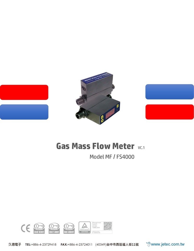
Jetec MF5000 Series User manual

Gas Mass Flow Meter VE.2.01
Model MF5000

Gas Mass Flow Meter
with MEMS calorimetric sensing technology
MF5000 Series
User Manual
Document No. 07-2022-M7 EN
Issue date: 2022.07
Revision: VE.2.01
久德電子
TEL:+886-4-23729418
FAX:+886-4-23724011
(40349)台中市西區福人街11號
Email: [email protected]
1 | P a g e
MF5000 User Manual

Attention!
Use with caution!
•Please carefully read this manual prior to operating this product.
•Do not open or modify any hardware which may lead to irrecoverable
damage.
•Do not use this product if you suspect any malfunctions or defection.
•Do not use this product for corrosive media or in a strong vibration
environment.
•Use this product according to the specified parameters.
•Only the trained or qualified personnel shall be allowed to perform
product services.
•Be cautious for the electrical safety, even it operates at a low voltage,
any electrical shock might lead to some unexpected damages.
•The gas to be measured should be clean and free of particles. Do not apply
this meter for liquid medium.
•Do not apply for any unknown or non-specified gases that may
damage the product.
•For remote data, please be sure the meter is properly configured.
2 | P a g e
MF5000 User Manual

Table of Contents
1. Overview .................................................................................................. 5
2. Receipt / unpack of the products ................................................................ 6
3. Knowing the products ............................................................................... 7
3.1. Product description ................................................................................................. 7
3.2. LCD description ....................................................................................................... 7
3.3. Power and data cable description ............................................................................. 8
3.4. Mechanical dimensions ............................................................................................ 9
4. Installation .............................................................................................. 10
5. Operation and MENU description .............................................................. 13
5.1 Check the product specifications ............................................................................ 13
5.2 Check the leakage ................................................................................................. 13
5.3 Power the meter and digital data connection .......................................................... 13
5.4 Meter MENU descriptions ...................................................................................... 14
5.4.1 Starting the measurement ........................................................................................... 14
5.4.2 MENU entry with a verified password ........................................................................... 15
5.4.3 Set the RS485 Modbus address .................................................................................... 15
5.4.4 Set the RS485 communication baud rate ...................................................................... 16
5.4.5 Reset or calibrate the offset ......................................................................................... 16
5.4.6 Gas conversion factor (GCF) for different gas measurement ............................................ 17
5.4.7 Set the 2nd-correction factor ....................................................................................... 18
5.4.8 Set the Response time ................................................................................................. 18
5.4.9 Set the unit for the accumulated or totalized flow rate ................................................... 19
5.4.10 Set the unit for the instant flow rate ............................................................................. 19
5.4.11 Change the default password ....................................................................................... 20
5.4.12 Reset the accumulated or totalized flow rate ................................................................. 20
5.4.13 Reset the 2nd-correction factor .................................................................................... 21
5.4.14 Exit the MENU ............................................................................................................ 21
5.4.15 MENU key sequence for the settings............................................................................. 22
5.5 RS485 Modbus communication protocol ................................................................. 22
3 | P a g e
MF5000 User Manual

5.5.1 Hardware connection .................................................................................................. 23
5.5.2 Communication parameters ......................................................................................... 23
5.5.3 Frame ........................................................................................................................ 24
5.5.4 Function codes ........................................................................................................... 24
5.5.5 Registers .................................................................................................................... 24
5.6 Analog (4 ~ 20 mA) output ..................................................................................... 28
6. Product selection .....................................................................................29
7. Technical specifications ............................................................................ 30
7.1 Specifications ....................................................................................................... 30
7.2 Pressure loss ......................................................................................................... 31
8. Technical notes for the product performance ............................................. 34
8.1 Measurement principle .......................................................................................... 34
8.2 Precautions for the best performance of the product ............................................... 34
8.2.1 Comparison with a third party reference meter .............................................................. 34
8.2.2 Particle contamination and fluidic cleanness ................................................................. 35
8.2.3 Apply to a different gas medium................................................................................... 35
9. Troubleshooting ...................................................................................... 36
10. Service contact ........................................................................................ . 37
Appendix I: Product evaluation kit ..................................................................38
Appendix II: Document history ....................................................................... 39
4 | P a g e
MF5000 User Manual

1. Overview
All contact information can be found at the end of this manual.
This manual provides essential information for the operation of the 3rd generation of the MF5000
series of gas mass flow meters for general-purpose gas metrology. The product performance,
maintenance, and trouble-shooting as well as the information for product order, technical support,
and repair are also included.
MF5000 mass flow meters are designed for general purpose precise industrial gas measurement,
monitor, or control. The meter series cover a wide dynamic flow range with a working pressure rating
of up to 1.5MPa, and a temperature ranging from -20 to 60°C.
The meters are operated with Siargo’s proprietary MEMS calorimetric mass flow sensors together
with the smart control electronics. The sensor surface is passivated with silicon nitride ceramic
materials and with a water/oil proof nano-coating for performance and reliability. The meter body is
made of stainless steel SUS 304 that is ready for application of most gases.
This new release offers applications in a hazardous zone (Ex ia IIC T4 Gb, equivalent to Class I, Div. 1,
zone 0, Group A, T4) as well. It also boosts the protection class to IP66 and offers additional
mechanical connection flexibility with both male and female connectors which can be further
adapted with any other threaded ones. The electrical interface is changed from DB9 to M12 for
better protection.
5 | P a g e
MF5000 User Manual

2. Receipt / unpack of the products
Upon receipt of the products, please check the packing box before the dismantlement of the packing
materials. Ensure no damages during shipping. If any abnormality is observed, please contact and
notify the carrier who shipped the product and inform the distributors or sales representatives if the
order is not placed directly with the manufacturer, otherwise, the manufacturer should be informed
as well. For any further actions, please refer to the return and repair section in this manual.
If the packing box is intact, proceed to open the packing box, and you shall find the product (either
the meter or the meter with the valve per the actual order). The power adapter and/or data cable as
shown below may also be found according to your actual order.
Flow meter data cable
Figure 2.1: MF5000 flow meter and data cable
Please check immediately for the integrity of the product as well as the power and data cable, if any
abnormal is identified, please notify the distributor/sales representative or manufacturer as soon as
you can. If any defects are confirmed, an exchange shall be arranged immediately via the original
sales channel. (Note: the LCD screen shall not be lighted until the power cable is plugged in). This
user manual shall also either be included in the packing box or via an online request for an electronic
version. In most cases, this manual shall be made available to the customer before the actual order.
The cable is a standard one with an M12 connector.
6 | P a g e
MF5000 User Manual

3. Knowing the products
3.1.Product description
Figure 3.1: MF5000 parts description
3.2.CD description
Figure 3.2: LCD symbol illustration.
The LCD provides all information that the product measures. Some symbols are reserved for
future upgrades, and will not be lighted during the operation. The following table details the
meaning of each of the symbols.
Meter body
LCD display
MENU keys
NPT or other
connectors
Flow direction
Electrical interface, M12
7 | P a g e
MF5000 User Manual

Table 3.1: Symbols description
USER
The top row only displays when communication or other user-defined
function is in process.
Total
The middle row displays the accumulated or totalized flow rate in
Nm3(Normalized cubic meters) or SCF (Standard cubic feet). Here
the standard (normalized) conditions refer to 20°C, 101.325kPa.
Flowrate
The bottom row displays the instant flow rate in SLPM (Standard
liters per minute), Nm3/h (Normalized cubic meters per hour), or
SCFM (Standard cubic feet per minute)
E1
Error 1 –Sensor error
E2
Error 2 –ADC error
E3
Error 3 –RTC error
E4
Error 4 –EEPROM error
E5
Error 5 –Oscillator (crystal) error
Temperature, for models with temperature option
P
Pressure, for models with pressure option
*Note: Both the pressure and temperature sensors can be integrated with the current product
but not with the default models. Please contact the manufacturer for further
information.
3.3.Power and data cable description
Table 3.2: MF5o00 wire (M12) assignments.
Socket Cable
Figure 3.3: MF5000 socket and cable
Wire
Color
Definition
1
Brown
12 ~ 24 Vdc
2
White
RS485 B (-)
3
Blue
GND, common ground
4
Black
RS485 A (+)
5
Gray
4 ~ 20mA output
8 | P a g e
MF5000 User Manual

3.4.Mechanical dimensions
Figure 3.4: MF5000 meter dimensions
Model
DN (mm)
D (NPTM)
L
MF5003
3
1/8”
138
MF5006
6
1/4”
144
MF5008
8
3/8”
144
MF5012
12
1/2”
150
MF5019
19
3/4”
182.5
9 | P a g e
MF5000 User Manual

4. Installation
Do not open or alter any part of the product which would lead to malfunction and irrecoverable
damage. It will also forfeit the terms of the warranty and cause liability.
The product at the time of shipment is fully inspected for its quality and meets all safety requirements.
Additional safety measures during the installation should be applied. This includes, but is not limited
to the leakage verification procedures, standard EDS (electrostatic discharge) precautions, and DC
voltage precautions. Other tasks such as calibration, part replacement, repair, and maintenance
must only be performed by trained personnel. Upon request, the manufacturer will provide
necessary technical support and/or training for the personnel.
The product is preferable to be installed horizontally. Flow direction should be aligned with the
arrow mark on the meter body. If the flowing fluid may have particles or debris, a filter is strongly
recommended to be installed upstream of the meter.
Figure 4.1: MF5000 meter installation
Please follow the following steps to complete the installation:
a) Upon opening the package, the product's physical integrity should be inspected to ensure no
visual damage.
b) Before installation of the product, please ensure that the pipe debris or particles or any other
foreign materials are completed removed.
c) Cautions during installation:
i) It is preferable to first install/connect the meter inlet and then the outlet end of the meter;
To ensure the measurement accuracy, an upstream straight pipe of length no less than
10DN and a downstream straight pipe of length no less than 5DN should be in place. Please
refer to the following recommended installation configuration.
10 | P a g e
MF5000 User Manual

(a) 90-degree elbow or T-piece (b) 2x90-degree elbow
Figure 4.2: MF5000 meter installation
(ii) If the upstream or downstream pipe size is different from that of the product, the size of
the installation line pipe diameter(s) should be larger than the flow channel (pipe) size of
the meters to be installed. For some typical situations, please follow the installation
recommendation detailed in the following sketches.
(c) 2x90-degree elbow, 3 D (d) Pipe size-reduction
(e) Pipe size expansion (f) Control valve at upstream or downstream
Figure 4.3: MF5000 meter installation
(iii) During installation, please make sure no foreign materials (such as water, oil, dirt, particles,
etc.) enter the installation pipeline.
11 | P a g e
MF5000 User Manual

d) Connect electrical wires per the wire definition in Table 3.3. Please be sure of the power supply
range (i.e., 12 ~ 24 VDC) and power supply polarization. If an adapter is other than the one
supplied by the manufacturer, make sure the adapter meets industrial standards and has all
safety certifications.
e) For the data communication wire connection, please follow the description in Table 3.3 and
make sure that the wires are correctly connected to the proper ports on your data
device/equipment. Please make sure the data cable meets industrial standards with proper
shielding.
f) Once the external power is successfully connected, the LCD should be lighted up with the proper
information displayed to work correctly.
g) Slowly open the valve(s) if any, upstream or downstream or both of the pipeline, and the meter
should then start to measure the flow in the pipeline. Note: because the meter has a large
dynamical measurement range, it could be normal if you see the small instant flow rate before
you open the valve as there could be some leakage. However, make sure the meter reads null
when there is no flow present in the pipeline.
h) This will conclude the installation.
Cautions
a) Don't alter any parts of the product.
b) Ensure the electrical connection is properly done per the instructions.
c) Make sure no mechanical stresses in the connections.
d) The strong electromagnetic interference sources close by or any mechanical shocks at the
pipeline may also create malfunctioning of the product.
e) Slowly open/close valves to prevent abrupt pulse flow impact.
12 | P a g e
MF5000 User Manual

5. Operation and MENU description
5.1 Check the product specifications
Before starting to use this product, check the product specifications that can be found in this manual
or the basic information located on the back panel of the product.
The detailed product technical specifications can be found in Section 7. For a specific application,
the pressure rating must not be higher than the system pressure to be measured, and the flow range
should also be within the specified ones. In most cases, the use of a high full-scale ranged meter for
the very low flow rate measurement often results in erroneous data. The gas to be measured must
also be consistent with that specified by the product. Be particularly cautious about the supplied
voltage indicated in the specification. A higher voltage may lead to irrecoverable damage, and a
lower voltage will not power the product for any desired functions.
For the best performance of the product, it is advised that the gas to be measured must be clean and
free of particles or other foreign materials.
5.2 Check the leakage
Check gas leakage before any measurement. If it is needed, pressurized nitrogen or air can be used
for the leakage check.
5.3 Power the meter and digital data connection
Although this product complies with the CE-required EMC regulations, it also requires the product to
be used according to the standard electrical device practice. Before connecting the meter with
external DC power or an AC-DC adapter, make sure the supply voltage is within the range of the
specified ones in Section 7. Be cautious that the standard electrical device precautions such as EDS
(electrostatic discharge) and DC voltage are observed. Excessive electrostatic discharge may
damage the product.
The manufacturer-supplied power and data cable have a locking fixture. Lock the cable and make
sure it is properly engaging and will not be accidentally got unplugged.
Half-duplex RS485 Modbus is used for digital data communication. Make sure the wires are properly
connected to the receiver side.
13 | P a g e
MF5000 User Manual

5.4 Meter MENU descriptions
Figure 5.1: MF5000 keyboard
The meter has a front 3-key keyboard for the user to set the desired functions, access data, and check
the status. The Menu key (M) is at the central position that allows the user to select a function and
confirmation or other related actions that will be detailed below. Two keys (“Left” and “Right”) to
select the menu and sub-menu.
5.4.1 Starting the measurement
Once the power is supplied and no abnormal issues are observed, the meter is ready to perform the
measurements. The default display is for the mass flow measurement having two numerical lines on
the LCD. The middle line is the accumulated or totalized flow rate, and the lower line is the instant
flow rate. The upper line will light up when the pressure or temperature option is selected.
The display characters are limited by the LCD capability, the following table is the illustration.
Left MENU Right
14 | P a g e
MF5000 User Manual

5.4.2 MENU entry with a verified password
At the flow measurement (main) display, press the central “M” MENU
key, it will enter into the password setting and verification MENU. The
default password is “11111”. If the password is incorrect, the display will
return to the main display.
To enter a new password, press the “Up” or “Down” key to change the
digit that flashes, and press the “M” key to confirm. Repeat this process
for all 5 digits and the meter will enter into the menu setting
interfaces/screen.
Subsequently, the MENU allows the user to:
➢Set Modbus address F2 - Addr
➢Change communication baud rate F3 - bPS
➢Reset or calibrate the offset F11 - oFFST
➢Enter the gas conversion factor (GCF) F12 - GCF
➢Set the 2nd-correction factor F14 - Corr
➢Change the response time F16 - rESPS
➢Set the unit for the accumulated or totalized flow rate F31 - UnT-A
➢Set the unit for the instant flow rate F32 - UnT-F
➢Change the default password F91 - PASS
➢Clear or reset the accumulated or totalized flow rate F92 - CLr-A
➢Reset the 2nd-correction factor F94 - rS2nd
➢Exit from the MENU F99 - qUIT
Note: During this process, the meter will continue to measure the flow without being interrupted.
5.4.3 Set the RS485 Modbus address
After the password is verified and entered into the MENU settings, press the “Up” or “Down” key
until the screen shows the F2 - Addr as indicated to the left.
The Modbus address has 3 digits, which can be any number
between 001 to 255. Press the “M” key to enter into the change
address screen. Press the “Up” or “Down” key to change the
flashing digits, and then press the “M” key to confirm. After the
address is set, the display will return to F2 - Addr, which indicates
the task is completed. Press the “Up” or “Down” key to select F99
-qUIT and the “M” key to exit the MENU and return to the Main
Display screen.
15 | P a g e
MF5000 User Manual

5.4.4 Set the RS485 communication baud rate
Following the above-mentioned steps, at the MENU setting screen, use the “Up” or “Down” key to
select F3 - bPS and then press the “M” key to set the RS485 communication baud rate.
There are 6 baud rates selectable, depending on your system
requirements: 4800, 9600, 19200, 38400, 57600, and 115200. The
default baud rate is 9600. Use the “Up” or “Down” key to select the
desired one and press the “M” key to confirm. The display will then
return to the F3 - bPS screen, which indicates the task is completed.
Use the “Up” or “Down” key to select F99 - qUIT and the “M” key to
exit the MENU and return to the Main Display screen.
5.4.5 Reset or calibrate the offset
After a certain time of usage, the meter’s offset (zero flow rate) might or might not have a small shift.
Or when you apply the meter for different gases, the offset might be shifted. To ensure
measurement accuracy, it is necessary to reset or calibrate the offset. Following the above-
mentioned steps, at the MENU setting screen, use the “Up” or
“Down” key to select F11 - oFFST. Before performing the task,
make sure there is absolutely no flow in the flow channel, otherwise,
it will create even bigger erroneous measurement results.
Press the “M” key to confirm the task, and it will open the sub-
MENU asking you to confirm. Use the “Up” or “Down” key to select
the desired one and press the “M” key to confirm. The display will
then return to the F11 - oFFST screen, which indicates the task is
16 | P a g e
MF5000 User Manual

completed. Use the “Up” or “Down” key to select F99 - qUIT and the “M” key to exit the MENU and
return to the Main Display screen.
5.4.6 Gas conversion factor (GCF) for different gas measurement
For the general purpose of the application, a gas conversion factor (GCF) can be applied to meter the
gas different from the default one or the one used for calibration. The GCF is determined by the
thermal calorimetric sensing principle as well as the meter fluidic dynamic design and the control
circuitry. Contact the manufacturer to obtain the values corresponding to the correct models.
The GCF for air is 1000.
Note: If the meter during purchase is ordered for a special real gas calibration, contact the
manufacturer before further proceeding.
Following the above-mentioned steps, at the MENU setting screen,
use the “Up” or “Down” key to select F12 - GCF. Press the “M” key
to confirm, and it will open the sub-MENU showing the current gas
conversion value. Use the “Up” or “Down” and the “M” confirming
key to input the desired value, and press the “M” key again to
complete the task. The display will then return to the F12 - GCF
screen, which indicates the task is completed. Use the “Up” or
“Down” key to select F99 - qUIT and the “M” key to exit the MENU
and return to the Main Display screen.
17 | P a g e
MF5000 User Manual

5.4.7 Set the 2nd-correction factor
Following the above-mentioned steps, at the MENU setting
screen, use the “Up” or “Down” key to select F14 - Corr and then
press the “M” key to set the 2nd-correction factor.
5.4.8 Set the Response time
Following the above-mentioned steps, at the MENU setting screen, use the “Up” or “Down” key to
select F16 - rESPS and then press the “M” key to set the response time.
There are 6 response time selectable: 125, 250, 500, 1000, 2000,
and 5000, unit is msec. The default response time is 125 msec.
Use the “Up” or “Down” key to select the desired one and press
the “M” key to confirm. The display will then return to the F16 -
rESPS screen, which indicates the task is completed. Use the “Up”
or “Down” key to select F99 - qUIT and the “M” key to exit the
MENU and return to the Main Display screen.
18 | P a g e
MF5000 User Manual

5.4.9 Set the unit for the accumulated or totalized flow rate
This function is to set the unit of accumulated flow. If one likes to switch between m3and SCF,
following the above-mentioned steps, at the MENU setting screen,
use the “Up” or “Down” key to select F31 - UnT-A. Press the “M”
key to confirm, and it will open the sub-MENU showing the current
unit of accumulated flow. Use the “Up” or “Down” and the “M”
confirming key to select the desired one, and press the “M” key
again to complete the task. The display will then return to the F31
–UnT-A screen, which indicates the task is completed. Use the “Up”
or “Down” key to select F99 - qUIT and the “M” key to exit the
MENU and return to the Main Display screen.
5.4.10 Set the unit for the instant flow rate
This function is to set the unit for an instant flow rate. If one likes to switch between SLPM, m3/h
(m3PH), and SCFM, following the above-mentioned steps, at the
MENU setting screen, use the “Up” or “Down” key to select F32 -
UnT-F. Press the “M” key to confirm, and it will open the sub-
MENU showing the current unit of accumulated flow. Use the “Up”
or “Down” and the “M” confirming key to select the desired one,
and press the “M” key again to complete the task. The display will
then return to the F32 - UnT-F screen, which indicates the task is
completed. Use the “Up” or “Down” key to select F99 - qUIT and
the “M” key to exit the MENU and return to the Main Display screen.
19 | P a g e
MF5000 User Manual
This manual suits for next models
5
Table of contents
Other Jetec Measuring Instrument manuals