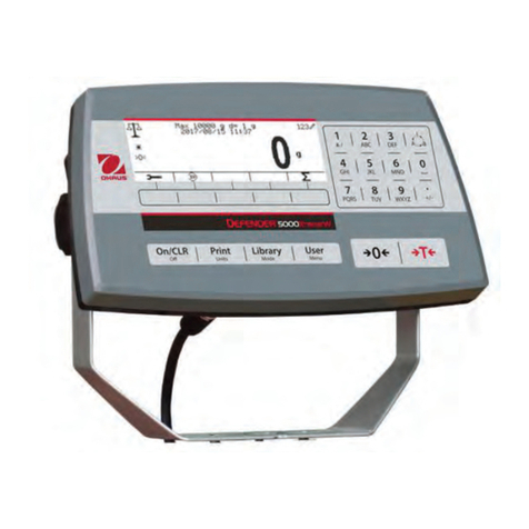
OHAUS TD52 User manual

TD52 Indicator
Ethernet Option
Instruction Manual
Interfaz de Ethernet
Manual de instrucciones
Interface Ethernet
Manuel d’instructions
Ethernet-Schnittstelle
Bedienungsanleitung
Interfaccia Ethernet
Manuale di istruzioni
以太网选件
使用说明书
이더넷 인터페이스
사용 설명서
ディフェンダー 5000
イーサネット インターフェイス
取扱説明書
Дополнительный интерфейс
Ethernet для весового терминала TD52
Руководство по эксплуатации
Manual_TD52_Ethernet_V1


EN-1
INTRODUCTION
This Ethernet interface kit is for use with the Defender®5000 TD52 indicators.
KIT CONTENTS
Cable
Screws(3)
Ethernet Cable
Ethernet PC board
INTERFACE INSTALLATION
Install the Ethernet Interface on the underside of the indicator as shown.
For TD52P:
1. Separate the indicator from the base by loosening load cell cable male connector. Remove
the interface option cover.
Load cell cable male connector
Interface option cover

EN-2
2. Break off the rib of the interface option cover as shown.
3. Connect the cable to the main board connector.
4. Install the Ethernet board. Secure it with the 3 screws. Connect the cable
to Ethernet board 9 Pin Connector.
Rib
Cable
Main board connector 1
9 Pin Connector
Screw

EN-3
5. Place the cord in the slot and put the interface option cover back on.
For TD52XW:
1. Remove the 6 sealing screws to open the rear housing. Remove the M25 hole plug as
shown.
2. Take the rear housing down from the front housing as shown.
Slot
Screw
M25 hole plug

EN-4
3. Connect the cable to the main board connector.
4. Install the Ethernet board. Fix the Ethernet board by 4 plastic clips and 2 position ribs.
(Note: the slots of the accessory board align with the 2 position ribs as shown.)
Connect the cable to the Ethernet 9 Pin Connector.
Cable
Main board connector
Slot
9 Pin connector
Position Rib

EN-5
5. Disassemble the cable gland by loosening the cap nut and removing the rubber seal. Pass
the Ethernet cable through the cap nut; then spread the rubber seal and place it over the
cable. Now pass the cable through the body of the cable gland.
6. Put the rear housing back on the front housing. Install the 6 sealing screws (Torque is
1.8N*m± 0.5). Insert the Ethernet cable through the housing and connect it to the Ethernet
board.
7. Install the body of the cable gland into the rear housing. Tighten the cable gland.
8. Push the rubber seal into the body of the cable gland.
Ethernet cable
M25 Cable gland
Cap nut
M25 Hole
Cable gland
Rubber seal

EN-6
9. Install the cap nut onto the body of the cable gland. Tighten the cap nut.
For TD52XW with reversed rear cover:
1. Remove the 6 sealing screws to open the rear housing. Remove the M25 hole plug as
shown.
2. Take the rear housing down from the front housing as shown.
Cap nut of M25 gland
Screw
M25 hole plug
Load cell cable male connector

EN-7
3. Connect the cable to the main board connector 1.
4. Install the Ethernet board. Fix the Ethernet board by 4 plastic clips and 2 position ribs.
(Note: the slots of accessory board match with the 2 position ribs as shown)
Connect the cable to the Ethernet 9 Pin Connector.
cable
Main board connector 1
Slot

EN-8
5. Disassemble the cable gland by loosening the cap nut and removing the rubber seal. Pass
the Ethernet cable through the cap nut; then spread the rubber seal and place it over the cable.
Now pass the cable through the body of the cable gland.
6. Put the rear housing back on the front housing. Re-install the 6 screws (Torque is
1.8N*m± 0.5). Insert the Ethernet cable through M25 hole. (Note: the direction which is the hook
of the Ethernet plug face down).
7. Fasten the M25 gland to the rear housing.
Ethernet cable
M25 cable gland
Cap nut
Ethernet cable
9 Pin connector
Position rib

EN-9
8. Warp the rubber seal onto the Ethernet cable and push it to the hole.
9. Fasten the cap nut of M25 gland.
SETUP
Upon installation, the indicator will recognize the Ethernet Interface Kit and add relevant items to the
menu. Configure the indicator to the desired RS232 and printing parameters (refer to the indicator
User Manual for assistance in using the menus).
M25 Gland
Rubber seal
Cap nut of M25 gland

EN-10
Ethernet Connection
If DHCP is set to ON, the IP Address will be automatically assigned by the IP share or router. If the
DHCP is set to OFF, the user can setup the IP Address, Subnet mask, Gateway, Preferred DNS and
Alternate DNS. The Interface has a preset IP Address. The Port Number is always 9761 and cannot
be changed.
Note: After the setup of IP Address, Gateway, Preferred DNS and Alternate DNS, please reboot the
indicator to enable the setting.
OPERATION
Output
With the interface installed the indicator will operate in one of the following two ways:
Auto Print = off, Stable = on or off
Pressing PRINT will send the display data.
If Stable is set to On, the indicator will wait for a stable reading before sending the stable data.
Auto Print = not off, Stable = on or off
The indicator will automatically send data based on the settings in the Menu.
If Stable is set to On, only stable values will be sent.
Data sent from the Interface is in standard ASCII format terminated with a [CRLF] (carriage return-line
feed). For the output format please refer to the indicator's instruction manual.
Input
The indicator will respond to various commands sent via the interface adapter. Terminate the
following commands with [CRLF].
Commands
For the full list of commands, please refer to the indicator's instruction manual.
CONFIGURATION
The TD52 indicator connects an Ethernet option board through the RS232 interface. The baud rate
will be 19200. If the option board is not connected, the submenu will not display.
Communication
Options (bold is default, Red is read only)
Ethernet
Configuration
Host Name
OHETHER
MAC Address
00-11-22-33-44-55
Port
9761
Version
1.01
DHCP
Off, On
IP Address
169.254.1.1

EN-11
Communication
Options (bold is default, Red is read only)
Subnet Mask
255.255.255.0
Gateway
169.254.1.1
Primary DNS
169.254.0.1
Secondary DNS
169.254.0.1
Alt Pirnt CMD
'a' ~ 'z', 'A' ~ 'Z', P
Alt Tare CMD
'a' ~ 'z', 'A' ~ 'Z', T
Alt Zero CMD
'a' ~ 'z', 'A' ~ 'Z', Z
Reset
No/Yes
Print Setup
Assignment
Demand
Stable Only
Off, No
Auto On Stable
Mode
Load, Load and Zero
Auto On Accept
Interval
Time
1~50000
MT-Continuous
OH-Continuous
SICS
Select Template
Simple, Custom 1, Custom 2, Custom 3,
Custom 4, Custom 5
Edit Template
Field 1~ Field 100
Edit String
String 1~ String 10
Reset
No/Yes
Host Name
The Host Name is the name of the Ethernet option board in the network. It is "OHETHER" by default.
MAC Address
The Medium Access Control (MAC) Address of the Ethernet option board is not editable.
Port
The Ethernet option board has a TCP server, with the port of 9761 (unmodifiable).
DHCP
If the DHCP is set Off, the user must set IP Address, Subnet Mask, Gateway, Primary DNS and
Secondary DNS manually.
If the DHCP Client is set On and there is DHCP server in the network, IP Address, Subnet Mask,
Gateway, Primary DNS and Secondary DNS fields will be read-only and assigned automatically by
the network. If there is no DHCP server in the network, the DHCP Server of the Ethernet option board
will be the DHCP server of the network.
IP Address
IP is 192.168.0.1 by default.
Subnet Mask

EN-12
Subnet mask is 255.255.255.0 by default.
Gateway
Gateway is 169.254.1.1 by default.
Primary DNS & Secondary DNS
DNS value is not needed when the system connects to a LAN. And the DNS value is assigned by the
ISP when connecting to the internet.
Alternative Command
The alternative command of Print, Tare, Zero can be set to 'a' ~ 'z' or 'A' ~ 'Z'.
NOTE:
The submenu will display after the installation of Ethernet option board.
The configurations of other submenus are the same as in section 3.9.1.

EN-13
COMPLIANCE
Mark
Standard
This product complies with the applicable harmonized standards of EU Directives
2011/65/EU (RoHS) and 2014/30/EU (EMC). The EU Declaration of Conformity is
available online at www.ohaus.com/ce.
FCC Note
This equipment has been tested and found to comply with the limits for a Class A digital device,
pursuant to Part 15 of the FCC Rules. These limits are designed to provide reasonable protection
against harmful interference when the equipment is operated in a commercial environment. This
equipment generates, uses, and can radiate radio frequency energy and, if not installed and used in
accordance with the instruction manual, may cause harmful interference to radio communications.
Operation of this equipment in a residential area is likely to cause harmful interference in which case
the user will be required to correct the interference at his own expense.
Industry Canada Note
This Class A digital apparatus complies with Canadian ICES-003
Disposal
In conformance with the European Directive 2012/19/EU on Waste Electrical and
Electronic Equipment (WEEE) this device may not be disposed of in domestic waste.
This also applies to countries outside the EU, per their specific requirements.
Please dispose of this product in accordance with local regulations at the collecting
point specified for electrical and electronic equipment. If you have any questions,
please contact the responsible authority or the distributor from which you purchased
this device.
Should this device be passed on to other parties (for private or professional use), the
content of this regulation must also be related.
For disposal instructions in Europe, refer to www.ohaus.com/weee.
Thank you for your contribution to environmental protection.


ES-1
INTRODUCCIÓ N
Este kit de interfaz de Ethernet se utiliza con los Indicadores Defender®5000 TD52 y las bá sculas
D52.
CONTENIDO DEL KIT
Cable
Tornillos (3)
Cable Ethernet
Placa Ethernet de PC
INSTALACIÓ N DE LA INTERFAZ
Instalar la interfaz Ethernet en la parte inferior del indicador como se muestra.
Para TD52P:
1. Separe el indicador de la base aflojando el conector del cable macho para la celda de
carga. Retire la cubierta de la interfaz.
conector macho del cable de la
celda de carga
Cubierta de opciones de interfaz

ES-2
2. Cortar la lengü eta de la cubierta de la interfaz, como se muestra.
3. Conectar el cable al conector de la placa principal.
4. Instalar la placa Ethernet. Fijarla por mediació n de los 3 tornillos.
Conectar el cable al conector de 9 pines de la placa Ethernet.
Costilla
Conector de la placa
principal 1
Cable
empulgueras
Conector de 9 pines

ES-3
5. Colocar el cable en la ranura y, a continuació n, volver a colocar la cubierta de la interfaz.
Para TD52XW:
1. Quitar los 6 tornillos de sellado para abrir la carcasa trasera. Retirar el tapó n M25, como
se muestra.
2. Separar la carcasa trasera de la carcasa frontal como se muestra.
Ranura
empulgueras
Tapó n de orificio M25

ES-4
3. Conectar el cable al conector de la placa principal.
4. Instalar la placa Ethernet. Fijar la placa Ethernet mediante los 4 clips de plá stico y las 2
lengü etas de posició n.
(Nota: las ranuras de la placa de accesorios se alinean con las 2 lengü etas de posició n,
como se muestra).
Conectar el cable al conector Ethernet de 9 pines.
Conector de la placa
principal
Cable
Conector de 9 pines
Posició n Costilla
espacio
Other manuals for TD52
7
Table of contents
Languages:
Other OHAUS Measuring Instrument manuals
OHAUS
OHAUS CKW-55 User manual

OHAUS
OHAUS ST300-G User manual

OHAUS
OHAUS ST20C-A User manual
OHAUS
OHAUS ST400 User manual

OHAUS
OHAUS 5000 User manual

OHAUS
OHAUS ST20D User manual

OHAUS
OHAUS ST300-B User manual

OHAUS
OHAUS STARTER 2200 User manual

OHAUS
OHAUS ST300D-G User manual

OHAUS
OHAUS ST Series User manual