EN
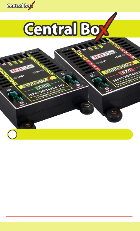
3.1 Power supply of Central Box 310/320
The Central Box 310/320 can only be powered from batteries
connected to BATT1 or BATT2. When selecting the power supply it
is necessary to follow the power requirements and the number of
the servos you use. Batteries for power supply must be sufficiently
large to prevent a decrease of the output voltage for servos when
loaded (voltage depression) and to allow the overload protection
function properly (Central Box 320).
Together, both power supply methods must be able to supply a 20A
continuous and 120A peak current. To take full advantage of
internal BEC we recommend to power the Central Box from three
Lixx cells.
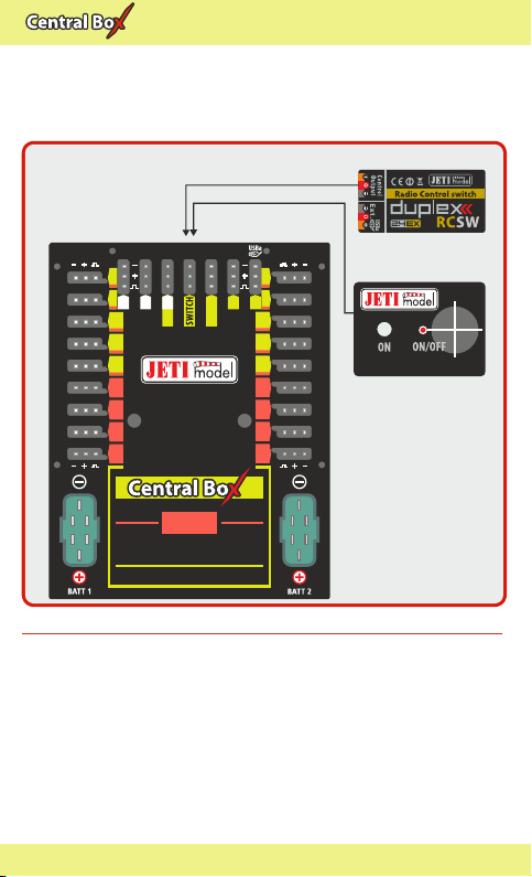
The power batteries are connected to the Central Box using MPX
connectors. The Central Box allows up to two batteries to be
connected. If the voltage of the batteries is the same, the power can
be used from both batteries at the same time. This rule applies to
the standard power supply. This means that the power battery
voltage should be greater than the required BEC voltage setting.
When the voltage of the batteries is different, the power is not
shared and each pack is isolated from the other. This allows you to
9 EN
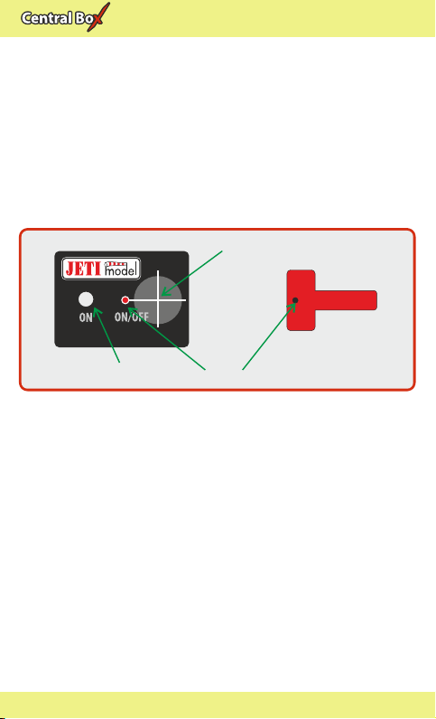
reasons, always switch the system off via magnetic switch before
disconnecting the power batteries.
When turning “ON”, connect the batteries first and then turn the
system on via magnetic switch. Keep the same rule when switching
off. First switch the system “OFF” via magnetic switch and then
disconnect the batteries.
3 Connection
The Central Box is connected to the power supply, receiver, servos,
controller/controllers and eventually sensors. Please follow the
subsequent general guidelines about proper connection of the
Central Box and these other components.