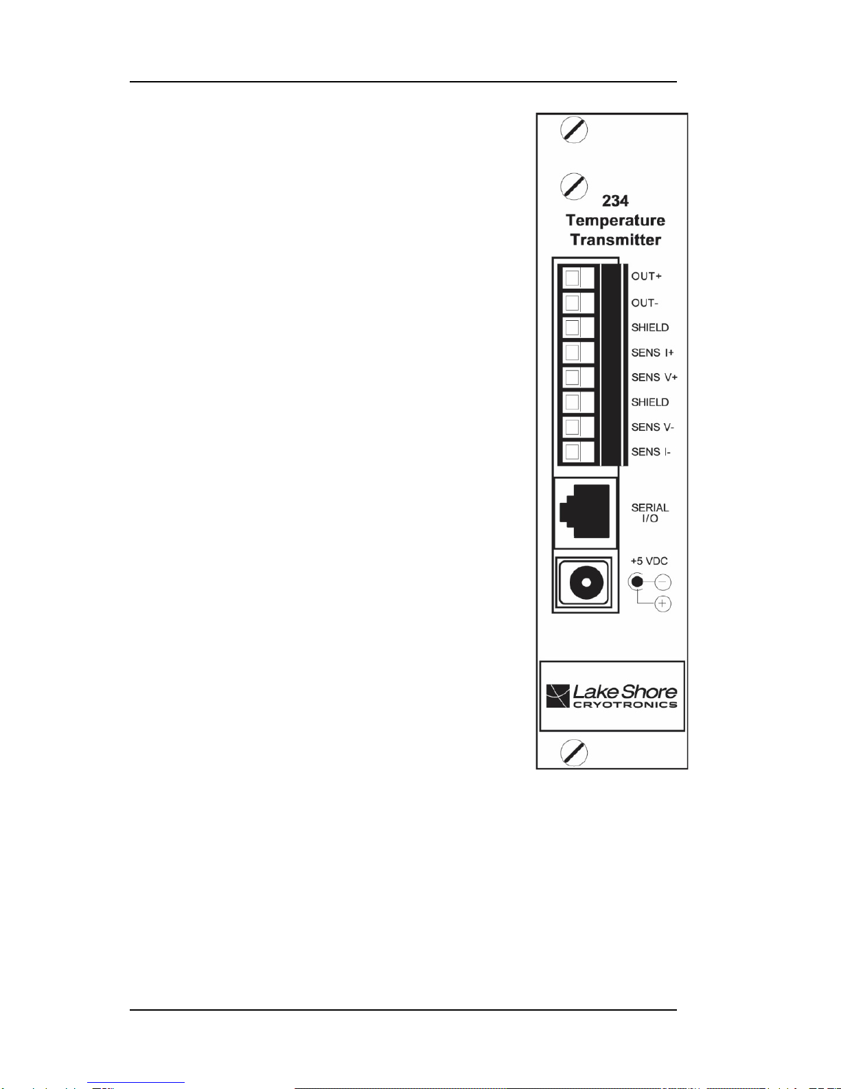
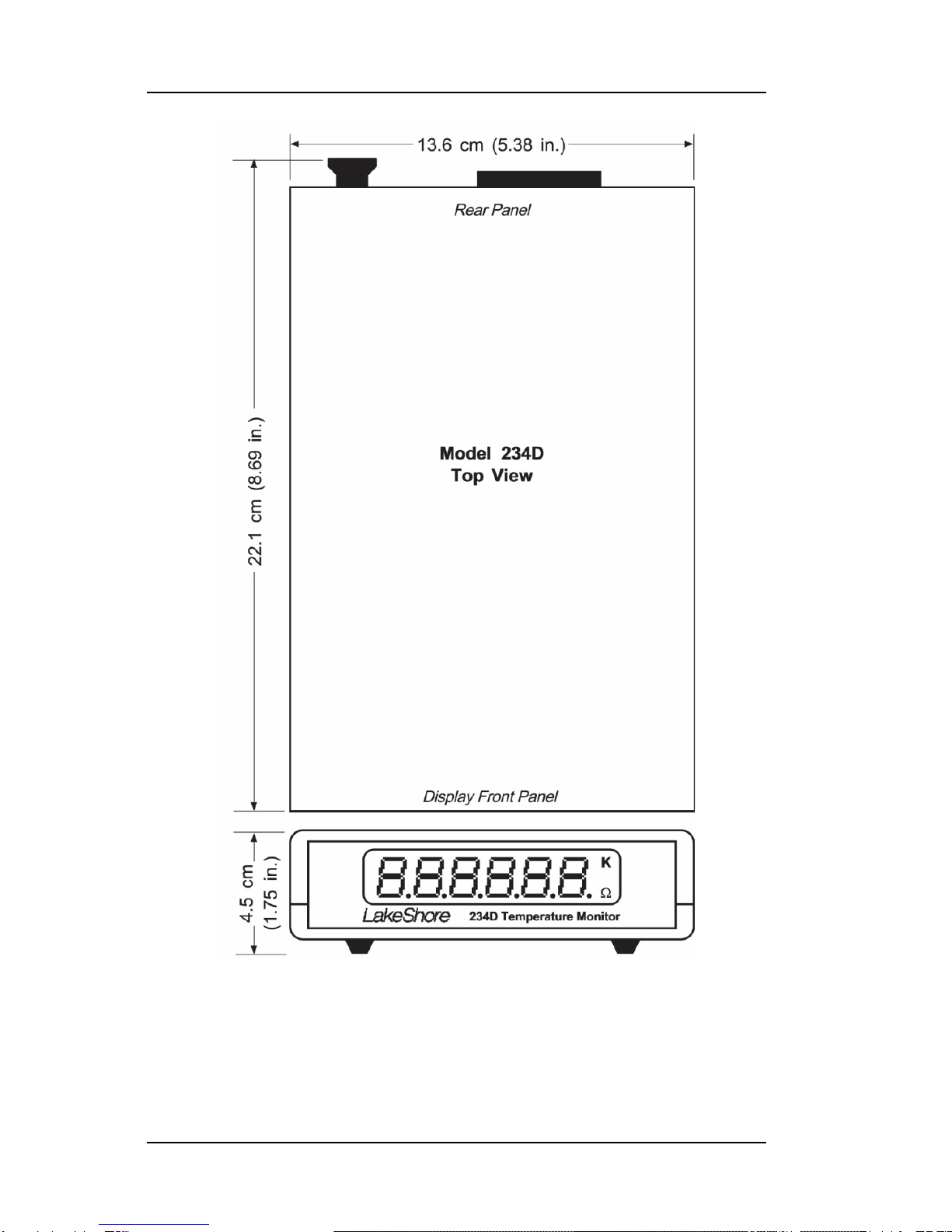
Lake Shore Model 234/234D User’s Manual
A
LIMITED WARRANTY STATEMENT – WARRANTY PERIOD: ONE (1) YEAR
1. Lake Shore warrants that this Lake Shore product (the “Product”) will be free from defects in materials
and workmanship for the Warranty Period specified above (the “Warranty Period”). If Lake Shore
receives notice of any such defects during the Warranty Period and the Product is shipped freight
prepaid, Lake Shore will, at its option, either repair or replace the Product if it is so defective without
charge to the owner for parts, service labor or associated customary return shipping cost. Any such
replacement for the Product may be either new or equivalent in performance to new. Replacement or
repaired parts will be warranted for only the unexpired portion of the original warranty or 90 days
(whichever is greater).
2. Lake Shore warrants the Product only if it has been sold by an authorized Lake Shore employee, sales
representative, dealer or original equipment manufacturer (OEM).
3. The Product may contain remanufactured parts equivalent to new in performance or may have been
subject to incidental use.
4. The Warranty Period begins on the date the Product ships from Lake Shore’s plant.
5. This limited warranty does not apply to defects in the Product resulting from (a) improper or inadequate
maintenance, repair or calibration, (b) fuses, software and non-rechargeable batteries, (c) software,
interfacing, parts or other supplies not furnished by Lake Shore, (d) unauthorized modification or
misuse, (e) operation outside of the published specifications or (f) improper site preparation or
maintenance.
6. To the extent allowed by applicable law, the above warranties are exclusive and no other warranty or
condition, whether written or oral,is expressed or implied. Lakeshore specifically disclaims anyimplied
warranties or conditions of merchantability, satisfactory quality and/or fitness for a particular purpose
with respect to the product. Some countries, states or provinces do not allow limitations on an implied
warranty, so the above limitation or exclusion might not apply to you. This warranty gives you specific
legal rights and you might also have other rights that vary from country to country, state to state or
province to province.
7. To the extent allowed by applicable law, the remedies in this warranty statement are your sole and
exclusive remedies.
8. Except to the extent prohibited by applicable law, in no event will lake shore or any of its subsidiaries,
affiliates or suppliers be liable for direct, special, incidental, consequential or other damages (including
lost profit, lost data or downtime costs) arising out of the use, inability to use or result of use of the
product, whether based in warranty, contract, tort or other legal theory, and whether or not lake shore
has been advised of the possibility of such damages. Your use of the Product is entirely at your own
risk. Some countries, states and provinces do not allow the exclusion of liability for incidental or
consequential damages, so the above limitation may not apply to you.
9. Except to the extent allowed by applicable law, the terms of this limited warranty statement do not
exclude, restrict or modify, and are in addition to, the mandatory statutory rights applicable to the sale
of the product to you. CERTIFICATION
Lake Shore certifies that this product has been inspected and tested in accordance with its published
specifications and that this product met its published specifications at the time of shipment. The accuracy and
calibration of this product at the time of shipment are traceable to the United States National Institute of
Standards and Technology (NIST); formerly known as the National Bureau of Standards (NBS), or to a
recognized natural standard. TRADEMARK ACKNOWLEDGEMENT
Manufacturers and sellers claim many designations as trademarks to distinguish their products. Where those
designations appear in this manual and Lake Shore was aware of a trademark claim, the designations appear
in initial capital letters with a ™ or ®symbol.
Apiezon®is a trademark of Biddle Instruments.
CalCurve™, Carbon-Glass™, Cernox™, Duo-Twist™, High-Temperature Cernox™, Quad-Lead™,
Quad-Twist™, Rox™, SoftCal™, and Thermox™ are trademarks of Lake Shore Cryotronics, Inc.
Teflon®is a trademark of DuPont De Nemours.
Copyright © 1993, 1995, 1997, 1999, 2003-04, 2009, and 2016 by Lake Shore Cryotronics, Inc. All rights
reserved. No portion of this manual may be reproduced, stored in a retrieval system, or transmitted, in any
form or by any means, electronic, mechanical, photocopying, recording, or otherwise, without the express
written permission of Lake Shore.