Produal Proxima WBU Guide

Wireless Produal Proxima® MESH 2,4 GHz
Commissioning and maintenance
5year
warranty

Published: 18.07.2019 2 (63)
Contents
1 Network properties................................................................... 4
1.1 Reading beacon data..................................................................................................5
2 Wireless network functions.......................................................7
2.1 Power consumption.................................................................................................... 7
2.2 Average groups......................................................................................................... 7
2.3 Alarms......................................................................................................................7
2.4 Input register cloning................................................................................................. 7
2.5 Value over bus (VOB).................................................................................................7
2.5.1 VOB value types............................................................................................. 8
2.6 Firmware updates...................................................................................................... 9
2.7 Measurement data sending interval..............................................................................9
2.8 Indicator lights........................................................................................................ 10
2.8.1 WBU indicator lights...................................................................................... 10
2.8.2 WTR indicator lights...................................................................................... 10
3 Building the wireless network................................................ 12
3.1 Designing the wireless network..................................................................................12
3.1.1 Signal range................................................................................................. 13
3.1.2 Effect of metal structures...............................................................................13
3.1.3 Wall penetration angle................................................................................... 14
3.2 Planning the wireless device positions........................................................................ 14
3.3 Placing and mounting the base unit........................................................................... 15
3.3.1 Wiring..........................................................................................................15
3.4 Mounting wireless transmitters.................................................................................. 17
3.4.1 Powering WTR.............................................................................................. 17
3.4.2 Wiring WTR24...............................................................................................17
3.4.3 Wiring WTR-IM............................................................................................. 17
3.5 Network configuring and commissioning procedure.......................................................18
4 Configuring the base unit settings.......................................... 20
4.1 Configuring average measurement groups...................................................................21
4.1.1 Available settings for average groups.............................................................. 22
4.2 Configuring alarms................................................................................................... 22
4.2.1 Available settings for alarms...........................................................................22
4.3 Configuring input register cloning...............................................................................23
4.3.1 Available settings for input register cloning...................................................... 23
4.4 Configuring Value Over Bus settings...........................................................................24
4.4.1 Available settings for value over bus............................................................... 24
4.5 Configuring communication settings........................................................................... 24
4.5.1 Available settings for communication............................................................... 25
4.6 Updating the device firmware.................................................................................... 25
4.7 Modbus................................................................................................................... 26
4.7.1 Modbus properties.........................................................................................26
4.7.2 Modbus function codes...................................................................................26
4.7.3 Modbus registers...........................................................................................27
5 Commissioning the wireless network......................................46
5.1 Setting up a new wireless network.............................................................................46
5.1.1 Adding devices to wireless network................................................................. 47
5.2 Reopening existing wireless project............................................................................ 51
Produal Oy | Keltakalliontie 18, FI 48770 Kotka, Finland | tel. +358 10 219 9100 | fax. +358 5 230 9210 | [email protected]
Information is subject to change without prior notice.
EN - 5401comm

Published: 18.07.2019 3 (63)
5.2.1 Removing devices from wireless network......................................................... 52
6 Configuring the wireless transmitters..................................... 53
6.1 Configuring user interface......................................................................................... 55
6.1.1 Available settings for user interface.................................................................55
6.2 Configuring measurement settings............................................................................. 55
6.2.1 Available measurement settings...................................................................... 56
6.3 Configuring change of value (COV) settings.................................................................56
6.3.1 Available change of value (COV) settings......................................................... 56
6.4 Tuning measurements...............................................................................................57
6.4.1 Available tuning values.................................................................................. 57
6.5 Transmitters' firmware updates.................................................................................. 57
6.5.1 Updating wireless transmitters' firmware using FOTA......................................... 57
6.5.2 Updating wireless transmitter firmware locally.................................................. 60
7 Troubleshooting the network.................................................. 63
7.1 Transmitter does not appear in the network................................................................ 63
7.2 All transmitters appear to be offline........................................................................... 63
7.3 Bluetooth is enabled and the transmitter doesn't appear in Produal MyTool®.....................63
Produal Oy | Keltakalliontie 18, FI 48770 Kotka, Finland | tel. +358 10 219 9100 | fax. +358 5 230 9210 | [email protected]
Information is subject to change without prior notice.
EN - 5401comm

Published: 18.07.2019 4 (63)
1 Network properties
Produal Proxima® wireless network is based on Lumenradio MIRA platform that provides a wireless
mesh network with unprecedented scalability and reliability. The Mira network is a self-healing multi-
hop network system that operate on the worldwide license-free 2,4 GHz ISM band. With patented
Future-Proof Coexistence Connectivity (FPCC) technologies we enable connectivity that can safely co-
exist along other wireless technologies, not being interfered or causing interference.
Important: The network uses 2,4 GHz frequency for communication. The frequency is an
ISM frequency band that can be used worldwide without any licence fees. If you are not sure
about the permissions to use this frequency in your country, contact your local authority for
more information.
Produal Proxima® WBU base unit supports up to 100 transmitters and separate repeaters are not
needed. The transmitters work as repeaters without any special configuration.
Only Wireless Produal Proxima® MESH 2,4 GHz products are compatible with the network.
MIRA is used for wireless communication between transmitters and base unit. Produal MyTool® can’t
communicate with wireless devices using MIRA. Bluetooth is used for communication between Produal
MyTool® and wireless devices. The Bluetooth communication can be active with only one device at a
time.
Note: The wireless devices can use only one communication protocol at a time. The device
is disconnected from the MIRA network when the Bluetooth is activated.
The wireless devices also support Bluetooth beacon messages. Beacon messages are one-way
messages from transmitters and base unit to Produal MyTool® application. These messages are used
to send information to application when monitoring or debugging the network. Signal scanner also
uses these beacon messages to calculate signal strength between device and application. The beacon
messages can be used also when the device is connected to a MIRA network.
Base unit sends the beacon messages continuously. The transmitter beacon messages can be activated
manually and the messages are active for one hour in following situations.
• During the transmitter installation to network, after the MIRA communication is activated.
Produal Oy | Keltakalliontie 18, FI 48770 Kotka, Finland | tel. +358 10 219 9100 | fax. +358 5 230 9210 | [email protected]
Information is subject to change without prior notice.
EN - 5401comm
Published: 18.07.2019 5 (63)
• Transmitter is restarted.
• The beacon messages are activated by pressing the button.
1.1 Reading beacon data
The wireless devices also support Bluetooth beacon messages. The beacon messages are one-way
messages that can be sent with same time with MIRA and Bluetooth communication. You can't install
transmitters to network using beacon data.
1. Start Produal MyTool®.
2. Press the Wireless installation projects button.
3. Press the Scan existing installations button.
4. Select the device from the list.
If the wireless device there are ??? on the signal strength, the device is out of the coverage area
or the beacon data has turned off (transmitters send the beacon data for one hour). To remove the
transmitters that are not in the area, press the Clear device list button.
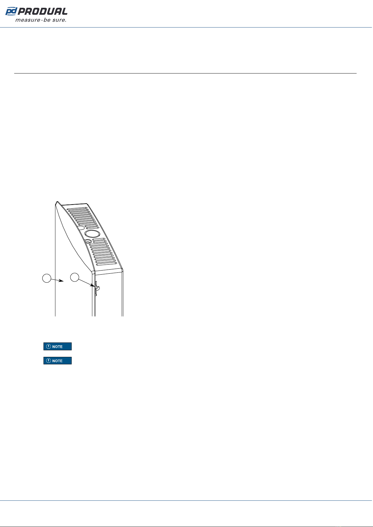
5. If the device is not showing in the list, press the connection button very shortly (under one
second).
The indicator light flashes quickly to indicate the button press.
A
B
A. Connection button
B. Indicator light
Note: Use a small screwdriver or a similar tool to push the button.
Note: If you press the button for over one second, the device Bluetooth activates and
the device is disconnected from the wireless network. Press the button again over one
second to deactivate the Bluetooth.
The transmitter sends the beacon messages for one hour. The beacon messages are also sent for
one hour after the transmitter is connected to a network or restarted.
Produal Oy | Keltakalliontie 18, FI 48770 Kotka, Finland | tel. +358 10 219 9100 | fax. +358 5 230 9210 | [email protected]
Information is subject to change without prior notice.
EN - 5401comm

Published: 18.07.2019 6 (63)
6. Press the Show device data button.
See the following table for more details about the Wireless Device Data view.
Parameter Description
SERIAL NUMBER Device serial number.
TRANSMITTER ID Transmitter ID number.
PARENT ID ID of the device that the transmitter is connected to. The ID 0 means that the transmitter is
directly connected to base unit. The ID 255 means that the transmitter is not connected to a
network.
TEMPERATURE Temperature measurement.
BATTERY Battery level. The battery level has six possible values: 99, 90, 50, 10, 5 and 1 %.
Not associated The transmitter doesn't see the network.
Associated The transmitter has found the network
and is connecting to it.
MESH NETWORK
STATUS
Transmitter's network
status.
Joined to a network The transmitter is connected to the
network.
MESH LINK
QUALITY
Signal quality. The signal quality value describes the connection quality to the parent device.
Values between 5 % and 100 % are acceptable values for functional network.
LAST SEEN Time that has elapsed since the last beacon message is received.
Produal Oy | Keltakalliontie 18, FI 48770 Kotka, Finland | tel. +358 10 219 9100 | fax. +358 5 230 9210 | [email protected]
Information is subject to change without prior notice.
EN - 5401comm

Published: 18.07.2019 7 (63)
2 Wireless network functions
2.1 Power consumption
The wireless devices can be powered with a battery or with wired power supply.
The battery powered transmitters measure the battery level two times a day. The battery level has six
possible values: 99, 90, 50, 10, 5 and 1 %. The value means that the battery level is at least the given
value, not the absolute value.
The battery life depends on the installation environment, used polling interval and firmware updates.
2.2 Average groups
The data collected from the transmitters can be arranged into five average groups. One average group
can be represent one measured property, such as temperature, humidity, carbon dioxide, etc. One
transmitter can be in several groups and one group can include only one measured property. The
average groups can be defined using Produal MyTool®.
The average value is calculated continuously from the latest available values. The highest and lowest
measurements are also available for the group.
Measurements that exceed or fall below a particular subset can be dropped out from the calculation.
For example, you can set that under 15 ºC and over 30 ºC measurements are dropped from the
average calculation. These limits are only available for temperature values.
2.3 Alarms
You can read the alarms based on the wireless network information from the base unit Modbus
registers. The alarms always include the device ID that is sending the alarm. The following alarms are
available.
• Battery level alarm. You can set the battery level that causes an alarm.
• Missing transmitter alarm.
• Measurement value alarm. You can set the measurement value limits that define the normal values.
An alarm is caused when the value drops under the low limit or rises over the high limit.
2.4 Input register cloning
With the input register cloning you can group the transmitter information to a smaller Modbus register
range. This enables the read multiple values Modbus function. The function can be used for reading
temperature measurements from the whole network, for example. You can set up to ten cloned
register value sets (0...9) that can be read from the same input register range.
The cloned input register range is from 18X00 to 18X99 according to the transmitter ID. The X is the
set number (0...9). The cloned registers are defined in the holding registers 18000...18009.
For example if you want to read a temperature value from the transmitter with ID 27, you can read
the values from the input register 18026. The cloned register set 0 is for temperature by default. The
original register for the transmitter temperature is 22651.
2.5 Value over bus (VOB)
The data can be transmitted in two directions, which allows also external values to be viewed on the
transmitters' displays. The base station has writeable Modbus registers, where the data can be written
and then send to the transmitters. The function is useful for example if BMS information must be
viewed on a transmitter display.
Produal Oy | Keltakalliontie 18, FI 48770 Kotka, Finland | tel. +358 10 219 9100 | fax. +358 5 230 9210 | [email protected]
Information is subject to change without prior notice.
EN - 5401comm
Published: 18.07.2019 8 (63)
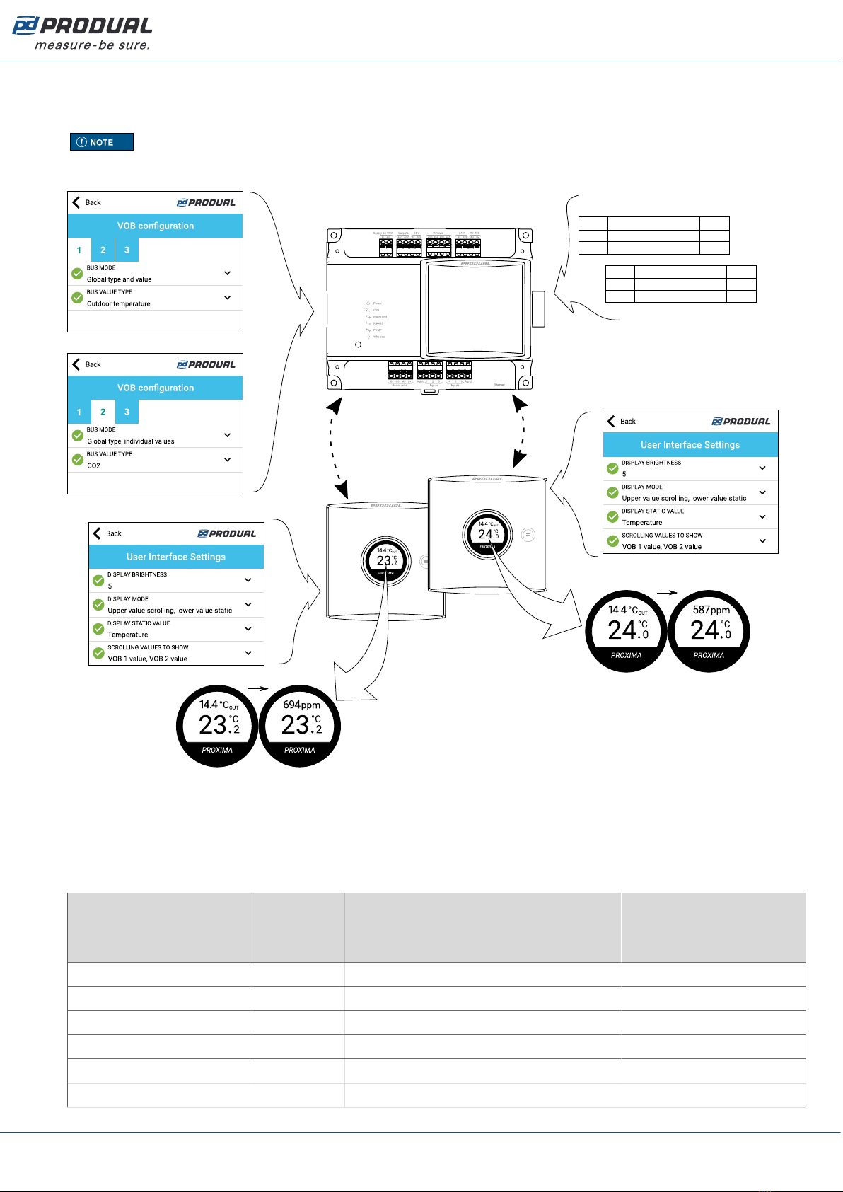
Two transmitter specific values can be shown on the displays. Also one global value (e.g. outdoor
temperature) can be shown on all displays in the network. The used value type is set to base unit
settings by using Produal MyTool®.
Note: The transmitter specific value type must be the same for all transmitters.
See the following figure for an example configuration.
Modbus
10910
10912
Enable value sending
Value
Reg. Description Value
1
144
11604 Value, ID 5
Reg. Description Value
587
11621 Value, ID 22 694
ID 5
ID 22
The VOB data is updated to transmitters in specific messages and the interval of these messages is
fixed to the network size. The update frequency can be calculated by using the following formula:
network size x 5 s. For example, if there are 10 transmitters and a base unit in the network, the
update interval is approximately 55 s.
2.5.1 VOB value types
MyTool value Modbus
register
value
Value description Range
No value 0 VOB is not in use. -
Temperature 1 Temperature. -100,0...100,0 °C
Humidity 2 Humidity. 0...100,00 %rH
CO2 3 CO2 value. 0...10000 ppm
Voltage 4 Voltage. 0...10,00 V
Current 5 Current. 0...20,00 mA
Produal Oy | Keltakalliontie 18, FI 48770 Kotka, Finland | tel. +358 10 219 9100 | fax. +358 5 230 9210 | [email protected]
Information is subject to change without prior notice.
EN - 5401comm

Published: 18.07.2019 9 (63)
MyTool value Modbus
register
value
Value description Range
Resistance (low) 6 Resistance, low. 0...2000,0 Ω
Resistance (high) 7 Resistance, high. 0...300000 Ω
Hot water consumption
(Finnish)
8 Hot water consumption (Finnish). 0...30000 m3 LV
Cold water consumption
(Finnish)
9 Cold water consumption (Finnish). 0...30000 m3 KV
Time 10 Time. 0...99 h
Indoor temperature 11 Indoor temperature. -100,0...100,0 °C CIN
Outdoor temperature 12 Outdoor temperature. -100,0...100,0 °C COUT
2.6 Firmware updates
The base unit firmware can be updated only locally using Produal MyTool®.
The transmitter firmware updates can be done locally or by using Firmware Over The Air (FOTA)
function.
The FOTA function updates the devices over the wireless network. The FOTA firmware update process
can take up from few minutes to several hours depending on the network size. The base unit updates
two devices at a time and then moves to the next devices until the whole network is updated to the
latest firmware version. The update process starts from the closest transmitter in the network.
Note: The FOTA function requires more power than the regular transmitter functioning.
Therefore the FOTA updates should be planned carefully in battery powered network. The
transmitter is not updated if the battery level is too low (under 10 %).
Note: The whole network is restarted after all devices are updated.
2.7 Measurement data sending interval
The measurement data can be read from the transmitters based on the base unit polling, with fixed
interval and with a Change of Value (COV) function.
Transmitters send the measurement information to the base unit according to the base unit polling
interval. The base unit requests the measurement information according to this interval even if other
data sending methods are also selected. The interval can be set to 60...65535 s (1 min...18 h).
In COV mode, the transmitter sends the measurement data also when the data changes. If the value
has changed more than the given hysteresis, this data is sent to the base station. The measurement is
continuous in transmitters with wired power supply. In battery powered transmitters, the measurement
is activated according to the network activity interval. The network activity interval can be set to
10...65535 s.
Note: Short interval may significantly shorten the battery life.
Note: The COV mode may significantly shorten the battery life if the hysteresis is set to
very low value.
If the fixed interval is selected in the transmitter, the measurement data is sent to the base unit also
with this interval. The interval can be set to 30...65535 s.
Note: Short interval may significantly shorten the battery life.
Produal Oy | Keltakalliontie 18, FI 48770 Kotka, Finland | tel. +358 10 219 9100 | fax. +358 5 230 9210 | [email protected]
Information is subject to change without prior notice.
EN - 5401comm

Published: 18.07.2019 10 (63)
2.8 Indicator lights
2.8.1 WBU indicator lights
The indicator lights indicate the device status.
Power The light is on when the supply voltage is connected.
Produal MyTool® is connected to the device.
2x 5 s 2x 5 s
All transmitters are online and working.
3x 5 s 3x 5 s
At least one transmitter is offline.
CPU
4x 5 s 4x 5 s
The network is not configured.
Room unit The light is not in use.
RS-485 The light indicates the communication in the RS‑485 port.
PUMP The light indicates that PUMP expansions are connected to the control unit.
Wireless Indicates the push of the connection button.
2.8.2 WTR indicator lights
The indicator light indicates the device status. The indicator light is active during the first hour after
connecting the power supply, or after the transmitter has lost connection to the network, or after the
device has booted.
Produal Oy | Keltakalliontie 18, FI 48770 Kotka, Finland | tel. +358 10 219 9100 | fax. +358 5 230 9210 | [email protected]
Information is subject to change without prior notice.
EN - 5401comm

Published: 18.07.2019 11 (63)
A
A. Indicator light
Produal MyTool® is connected to the device.
2x 5 s 2x 5 s
The device is connected to the network.
3x 5 s 3x 5 s
The device is searching the network.
4x 5 s 4x 5 s
The network is not configured.
The indicator light also indicates if the connection button is pressed.
Produal Oy | Keltakalliontie 18, FI 48770 Kotka, Finland | tel. +358 10 219 9100 | fax. +358 5 230 9210 | [email protected]
Information is subject to change without prior notice.
EN - 5401comm
Published: 18.07.2019 12 (63)
3 Building the wireless network
3.1 Designing the wireless network
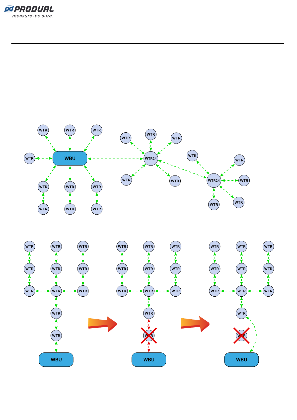
In the mesh network, the base unit should be located in the centre of the network to achieve the
optimal network functionality. However, the central base unit positioning is not always possible. In
these situations, you should consider carefully the used devices in the network.
Produal Proxima® MESH can be fully battery operated. If your network has transmitters with external
power supply, the network will prefer these when routing the messages. When designing a bigger
network these external power supply devices can be used as the backbone of the network. If there is
power loss in external power supply, battery operated devices will route traffic normally.
It is recommended to install more than one routing transmitter within the base unit signal range.
This improves the network functionality and reliability. The following figures illustrate the network re-
routing functionality when a routing transmitter is disconnected from network.
Produal Oy | Keltakalliontie 18, FI 48770 Kotka, Finland | tel. +358 10 219 9100 | fax. +358 5 230 9210 | [email protected]
Information is subject to change without prior notice.
EN - 5401comm

Published: 18.07.2019 13 (63)
3.1.1 Signal range
Because the radio signals are electromagnetic waves, the signal becomes weaker the further it travels.
The radio signal coverage is also decreased by specific materials that are in the propagation direction.
The radio waves can penetrate walls, but the signal is dampened more than in the direct line of sight
path. See the following table for the different construction material effect on the radio signal strength.
Material Range reduction compared to direct line of sight
Wood, plaster, uncoated glass 0...10 %
Brick, press board 5...35 %
Concrete, reinforced concrete 10...90 %
Metal, aluminium lining 90...100 %
3.1.2 Effect of metal structures
Metallic parts, e.g. wall reinforcements, thermal insulation metal foils and metallized heat-absorbing
glasses reflect radio waves. This creates a so called radio shadow behind the structure.
The radio transmission may work even if there are metallic obstacles on the direct path to the receiver.
The radio waves reach to the destination by reflecting from metallic objects and passing through non-
metallic objects (doors, windows, wooden walls). However, the radio signal range is strongly reduced.
The radio transmission problems can be avoided by placing the devices on a direct propagation path.
Wireless device
Metallic object
Wireless device
Wireless device
Produal Oy | Keltakalliontie 18, FI 48770 Kotka, Finland | tel. +358 10 219 9100 | fax. +358 5 230 9210 | [email protected]
Information is subject to change without prior notice.
EN - 5401comm

Published: 18.07.2019 14 (63)
3.1.3 Wall penetration angle
The wireless devices should be placed so that the radio signal goes through a wall as directly as
possible. The attenuation is higher the longer the signal travels inside the wall. Avoid installing the
devices in wall recesses.
Wireless device
Wireless device
Wireless device
Wireless device
3.2 Planning the wireless device positions
The device locations should be planned carefully by observing possible radio shadow places and other
restrictive factors. The radio coverage in commercial buildings is usually restricted by fire safety walls
that cause radio shadows. However, inside the fire protected sections, lightweight or glass partition
walls are commonly used.
1. Take the building floor plan.
2. Locate and mark all relevant radio shadows to the plan.
• Fire protection walls
• Lavatories
• Staircases
• Elevator shafts
• Big metallic furniture (e.g. cabinets)
Produal Oy | Keltakalliontie 18, FI 48770 Kotka, Finland | tel. +358 10 219 9100 | fax. +358 5 230 9210 | [email protected]
Information is subject to change without prior notice.
EN - 5401comm

Published: 18.07.2019 15 (63)
3. Plan the device locations.
Make sure the fixed power supply is available where needed. See the following table for power
supply options.
Power supplyDevice
Battery 24 Vac/dc
WBU x
WTR x
WTR24 x
WTR-IM x x
Note: For reliable range planning, you have to assume some unfavourable conditions.
Planning with a few meters smaller range offers reserve against the most typical bad
conditions. Bad conditions are often resulted from later environmental changes (people,
partition wall relocations, furniture, plants, etc.). Also the device real positions might
deviate from the plan.
4. Verify the device locations before final installation by checking the signal propagation paths.
5. Check the signal strength in the planned locations during commissioning and adjust as needed.
3.3 Placing and mounting the base unit
The ideal base unit installation place is the central location in the network area. The device should be
at least 10…15 cm away from the wall corner or concrete ceiling.
The base unit is designed for hidden installation, e.g. above a false ceiling, and doesn’t normally
require any additional cover for the cabling. However, the installation regulations may be different in
your country.
Important: Check the local installation regulations before making any installations.
It’s recommended to use cable ties or equivalent to have some pull relief and to tidy up the
installation. If a touch protection is required on the terminals, please use a CUCC cable cover.
The base unit can be mounted on the wall by screws or to a 35 mm DIN rail.
3.3.1 Wiring
CAUTION: Device wiring and commissioning can only be carried out by qualified
professionals. Always make the wirings while the power is switched off.
The device terminals are grouped according to the functions to avoid any wiring mistakes. There are
extra G and G0 terminals for connecting the separate supply voltage for other devices.
The terminals are designed for maximum of 1,5 mm2 cable area. Please note that the cables for
communication (RS‑485) should be twisted pair (2x2 pairs).
3.3.1.1 Top connectors
Supply 24 VAC
G24 Vac/dc supply.
Produal Oy | Keltakalliontie 18, FI 48770 Kotka, Finland | tel. +358 10 219 9100 | fax. +358 5 230 9210 | [email protected]
Information is subject to change without prior notice.
EN - 5401comm

Published: 18.07.2019 16 (63)
G0 Ground
Outputs
AD1
AD2 Not in use
24 V
G24 Vac output.
G0 Ground
Outputs
AD3
AD4
AO5
AO6
Not in use
24 V
G24 Vac output.
G0 Ground
RS-485
A+
B- RS-485 bus connection for Modbus RTU.
3.3.1.2 Bottom connectors
Room units
G
G0
A+
B-
Not in use.
Inputs
Agnd
1
2
3
4
5
6
Agnd
Not in use.
Produal Oy | Keltakalliontie 18, FI 48770 Kotka, Finland | tel. +358 10 219 9100 | fax. +358 5 230 9210 | [email protected]
Information is subject to change without prior notice.
EN - 5401comm
Published: 18.07.2019 17 (63)
Ethernet
Ethernet RJ-45 connector for Modbus TCP.
3.4 Mounting wireless transmitters
Place the wireless transmitters according to the plan avoiding radio shadows.
The device can be installed in dry surroundings (IP20) by screws on the wall surface or on the standard
flush mounting box. The recommended installation height is 150...180 cm.
The device position should be selected carefully. All the error factors that can affect to the
measurements should be eliminated as well as possible. The following list defines the typical
measurement error factors.
• direct sun light
• occupant proximity
• air flow coming from windows or doors
• air flow coming from ventilation nozzles
• air flow coming from the flush mounting box
• differential temperature caused by external wall
3.4.1 Powering WTR
WTR models have a battery for power supply. The devices are delivered with a with a battery that is
disconnected by using a disconnecting strip. Open the cover and remove the strip to enable the power
supply for the device.
3.4.2 Wiring WTR24
The WTR24 models have connectors for 24 Vac/dc supply.
CAUTION: Device wiring and commissioning can only be carried out by qualified
professionals. Always make the wirings while the power is switched off.
G
G0
A+
B-
G24 Vac/dc supply
G0 Ground
A+
B- Not in use.
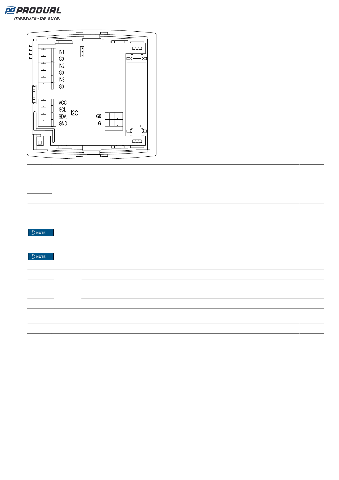
3.4.3 Wiring WTR-IM
CAUTION: Device wiring and commissioning can only be carried out by qualified
professionals. Always make the wirings while the power is switched off.
Produal Oy | Keltakalliontie 18, FI 48770 Kotka, Finland | tel. +358 10 219 9100 | fax. +358 5 230 9210 | [email protected]
Information is subject to change without prior notice.
EN - 5401comm
Published: 18.07.2019 18 (63)
IN1
G0 Input 1 (0...10 V or NTC 10 or digital).
IN2
G0 Input 2 (0...10 V or NTC 10 or digital).
IN3
G0
Input 3 (0...10 V or NTC 10 or digital). The input supports energy harvesting from 0...10 V signal when
the device is battery powered. The harvesting is active if the signal is over 4 V.
Note: When using 0...10 V inputs, the input potential must be the same that is used in the
connected 0...10 V device. Use common G0 with the connected device's power supply, for
example.
Note: Use NO type contact for digital input, if the device is only battery powered. NC
requires power and that significantly shortens the battery life.
VCC 3...5 Vdc
SCL Serial clock line.
SDA Serial data line.
GND
I2C
models
0 V
G0 0 V
G10...30 Vdc / 12...28 Vac
3.5 Network configuring and commissioning procedure
It's recommended to follow the following procedure to be able to configure and commission the
wireless network successfully.
1. Design the network and place the devices.
See the section Building the wireless network on page 12.
2. Configure the base unit settings.
See the section Configuring the base unit settings on page 20.
3. Set up the network.
See the section Setting up a new wireless network on page 46.
4. Configure transmitter settings.
See the section Configuring the wireless transmitters on page 53.
Produal Oy | Keltakalliontie 18, FI 48770 Kotka, Finland | tel. +358 10 219 9100 | fax. +358 5 230 9210 | [email protected]
Information is subject to change without prior notice.
EN - 5401comm

Published: 18.07.2019 19 (63)
5. Connect the transmitters to the network starting from the closest transmitter.
See the chapter Adding devices to wireless network on page 47.
Produal Oy | Keltakalliontie 18, FI 48770 Kotka, Finland | tel. +358 10 219 9100 | fax. +358 5 230 9210 | [email protected]
Information is subject to change without prior notice.
EN - 5401comm
Published: 18.07.2019 20 (63)
4 Configuring the base unit settings
To configure the device, you first need to connect it to Produal MyTool® application. When the device is
connected to application, you can make changes to the configuration.
1. Connect the supply voltage to the base unit.
2. Start Produal MyTool®.
3. Press the Devices button.
The device list shows the devices that has Bluetooth activated.
Note: The Bluetooth is enabled when the supply voltage is connected for the first time.
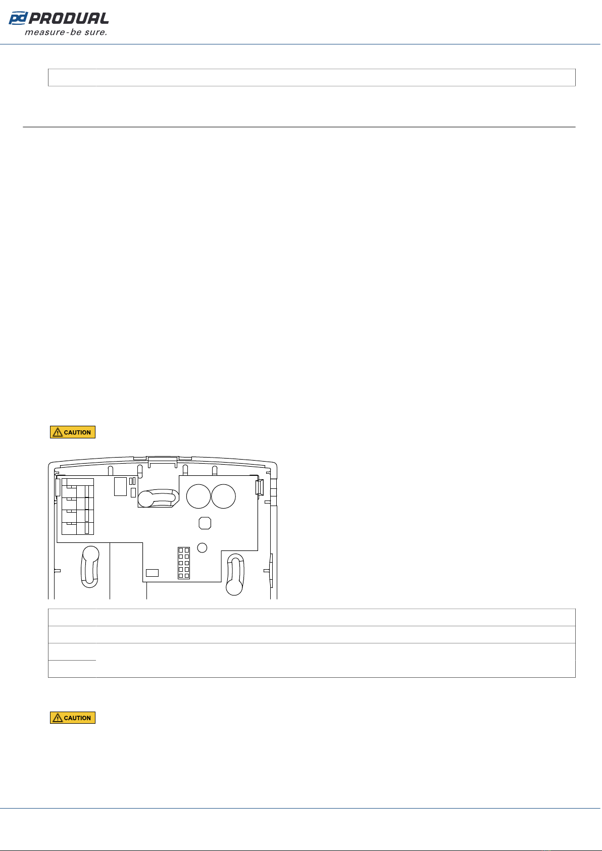
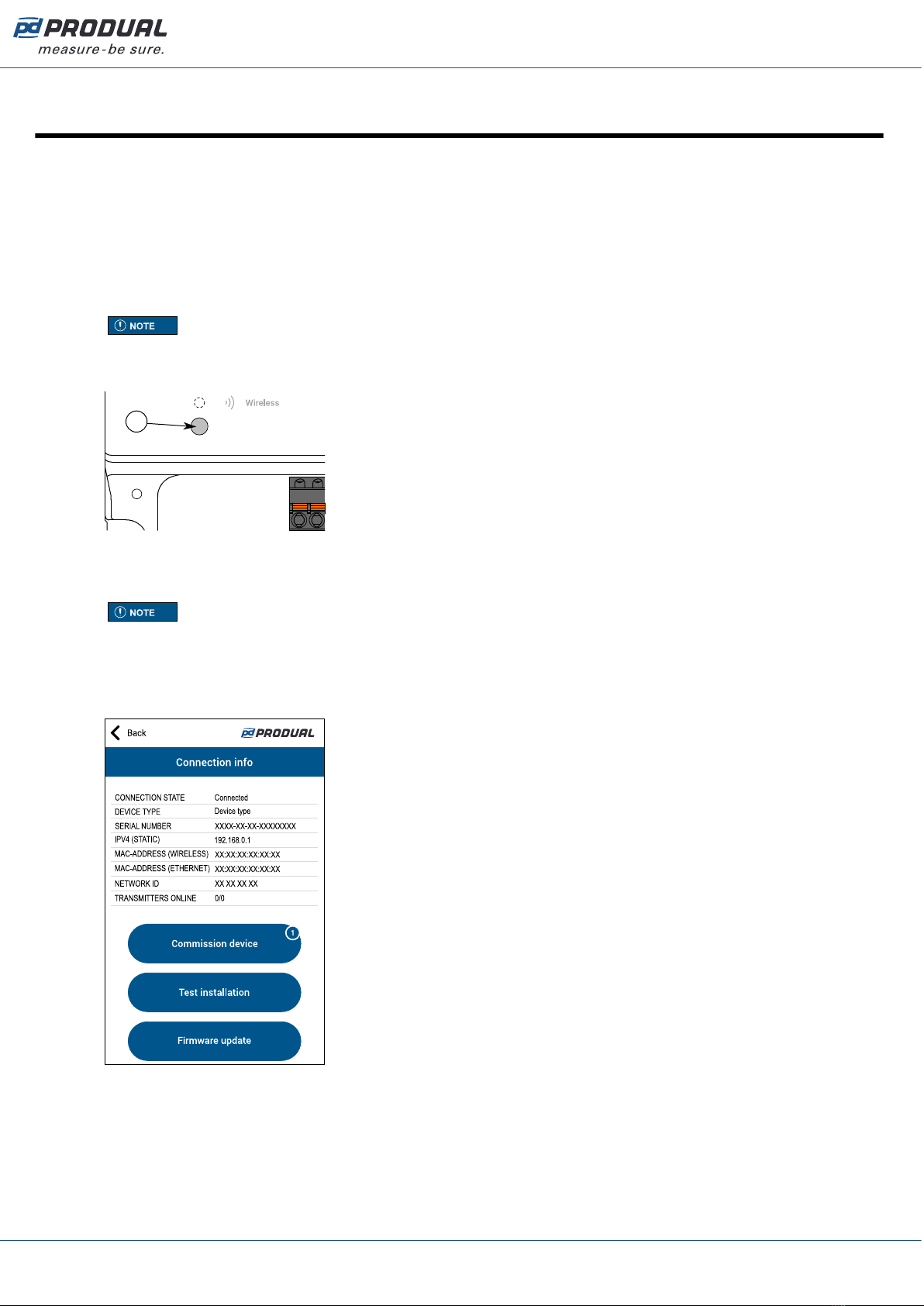
4. If the device is not showing in the list, press the connection button until the Wireless indicator light
flashes to enable the Bluetooth in the device.
A
A. Connection button
The indicator light should flash after pressing the button for one second.
Note: Use a small screwdriver or a similar tool to push the button.
5. Select the device from the list.
6. Press the Connect button.
CPU indicator light is illuminated continuously when Produal MyTool® is connected to the device.
Produal Oy | Keltakalliontie 18, FI 48770 Kotka, Finland | tel. +358 10 219 9100 | fax. +358 5 230 9210 | [email protected]
Information is subject to change without prior notice.
EN - 5401comm
This manual suits for next models
3
Table of contents
Other Produal Transmitter manuals


Popular Transmitter manuals by other brands


NIVELCO
NIVELCO EasyTREK SP-300 Installation and programming manual

iKarus
iKarus Opticc 6 Sport instruction manual

Lightware
Lightware WP-UMX-TPS-TX120-US Black quick start guide

RKI Instruments
RKI Instruments 65-2322-04SS Operator's manual

Teledyne Analytical Instruments
Teledyne Analytical Instruments INSTA TRANS-XD operating instructions

Erone
Erone SETL39433AM2 manual


