Pavone Systems DAT 1400 User manual

PAVONESYSTEMS
TECHNICAL MANUAL
DAT 1400 Weight transmitter/indicator with RS232 serial, analog and Fieldbus output
Software version PDAT01

Page II

Rel ID 19500402 SW 2.5
Page 1
TABLE OF CONTENTS
PRECAUTIONS.............................................................................................. Page 2
INTRODUCTION ........................................................................................... Page 3
TECHNICAL FEATURES ................................................................................... Page 5
INSTALLATION .............................................................................................. Page 6
FRONT PANEL OF THE INSTRUMENT .............................................................. Page 14
USING THE KEYBOARD ................................................................................. Page 15
INFO DISPLAY ............................................................................................... Page 18
OPERATING FUNCTIONS ............................................................................. Page 19
SETTING....................................................................................................... Page 23
DIAGRAM OF THE MENU .............................................................................. Page 27
CONFIGURATION PARAMETERS..................................................................... Page 28
CALIBRATION................................................................................................ Page 28
ANALOG PARAMETERS ................................................................................. Page 33
SERIAL PARAMETERS...................................................................................... Page 35
INPUT/OUTPUT PARAMETERS......................................................................... Page 44
WEIGHING PARAMETERS .............................................................................. Page 48
FILTER - SETTING FILTER PARAMETERS .............................................................. Page 50
SETTING FUNCTIONAL FEATURES .................................................................. Page 52
SET DATE AND TIME...................................................................................... Page 55
UPLOAD/DOWNLOAD FUNCTION ................................................................ Page 56
ACCESS VIEWING ........................................................................................ Page 57
ALIBI MEMORY.............................................................................................. Page 58
SERIAL COMMUNICATION PROTOCOLS ........................................................ Page 59
FIELDBUS PROTOCOL .................................................................................... Page 71
TROUBLESHOOTING ..................................................................................... Page 84

Page 2
PRECAUTIONS
READ this manual BEFORE operating or servicing the instrument.
FOLLOW these instructions carefully.
KEEP this manual for future use.
WARNING
The purpose of this manual is to provide the operator with expla-
natory text and figures, the requirements and basic criteria for the
installation and correct use of the instrument.
The installation, maintenance and repair should only be carried
out by specialised personnel who have read and understood this
manual. “Specialised personnel” means personnel who, because
of their training and professional experience have been expressly
authorised by the plant Safety Officer to carry out the installation.
Power the instrument with a voltage whose value is within the limits
specified in the specifications.
The user is responsible for ensuring that the installation complies
with the provisions in force.
Any attempt to dismantle or modify the instrument which is not
expressly authorised will invalidate the warranty and will relieve
Pavone Sistemi from all liability.
Installation and maintenance of this instrument must be entrustedto
qualified personnel only.
Be careful when performing inspections, tests and adjustments with
the instrument on.
Perform the electrical connections with the instrument unplugged
from the mains
Failure to observe these precautions may be dangerous.
DO NOT allow untrained personnel to work, clean, inspect, repairor
alter this instrument.

Page 3
INTRODUCTION
The DAT 1400 is a weight transmitter to be combined with the load cells to detect the weight in every
situation.
The module is easy to install and must be mounted on a 35 mm DIN rail or OMEGA bar. The weight,
the status of the instrument, the setting parameters and any errors are all clearly shown on the display.
The 4 keys below the display permit easy use of these functions: ZERO-SETTING, TARE, GROSS/NET
switching, setting of the weight set-points, configuration, and both theoretical and real calibration.
The DAT 1400 uses the RS232 serial port with ASCII protocols, in order to be connected to a PC, PLC
and remote units with a maximum distance of 15m, above which you must use the serial port RS422/
RS485 which also allows connection with the MODBUS RTU protocol up 32 addressable instruments.
Availability of the most widespread fieldbuses, as an alternative to port RS485, also makes it possible
to interface the transmitter with any supervision device currently offered by the market.
There is also a USB 2.0 port for easy interfacing with the PC via a utility software which can be pro-
vided with it.
They are always 2 programmable weight set-points and control of the maximum weight value reached
(peak).
In addition you can have the analog output in current or voltage even with a FIELDBUS.
Available versions:
• DAT1400: weight transmitter with RS232 serial output, USB, RS485 and peak function. Suppor-
ted protocols are Modbus RTU, continuous, slave and on demand. Two programmable set points,
2 inputs and Peak function.
• DAT1400/A: version with the analog output.
• DAT1400/PROFINET: weight transmitter with RS232 serial output, USB and PROFINET.
• DAT1400/ETHERNETIP: weight transmitter with serial output RS232 and ETHERNET IP.
• DAT1400/ETHERCAT: weight transmitter with serial output RS232 and ETHERCAT.
• DAT1400/ETHERNET: weight transmitter with serial output RS232 and ETHERNET.
• DAT1400/PROFIBUS: weight transmitter with serial output RS232 and PROFIBUS.
• DAT1400/CANOPEN: weight transmitter with serial output RS232 and CANOPEN.
PAVONE SISTEMI
Page 4
IDENTIFICATION PLATE OF THE INSTRUMENT
Always cite this data when requesting information or instructions concerning the instrument, as well as
the program number and version that are shown on the cover of the manual and on the display when
the instrument is switched on.
WARNINGS
The following procedures must be entrusted to qualified personnel.
All connections must be made with the instrument turned off.

Page 5
TECHNICAL FEATURES
Power supply 12 ÷ 24 Vdc ± 15 %
Max. absorption 5 W
Isolation Class II
Installation category Cat. II
Operating temperature -10°C ÷ +50°C (max humidity 85% without
condensate)
Storage temperature -20°C ÷ +70°C
Weight display 6 digit 7-segment red LEDs (h 14 mm)
Led 4 3mm indicator LEDs
Keyboard 4 keys
Overall dimensions 106 mm x 63 mm x 110 mm (l x h x d)
Assembly On support for DIN profile or OMEGA bar
Container material Self-extinguishing Noryl (UL 94 V1)
Connections Removable terminal boards pitch 5.08.
Load cells power supply 5 Vcc/120 mA (max 8 cells x 350Ω in parallel) short-
circuit protected
Input sensitivity 0.02 μV min.
Linearity < 0.01% of full scale
Temperature drift < 0.001% of full scale / C°
Internal resolution 24 bit
Displayed weight resolution Up to 999,999 divisions on useful capacity
Measuring range From –3,9 mV/V to +3,9 mV/V
Weight acquisition frequency 12 Hz - 1000 Hz
Digital filter Selectable 0,5 ÷50 Hz (up to 1000 Hz in manual)
Weight decimal number from 0 to 4 decimal digits
Zero calibration and full scale Automatic (theoretical) or executable from the
keyboard.
Logic outputs 2 optoinsulated (free contact) max 24Vdc / 100 mA
ea.
Logic inputs 2 optoinsulated 24 Vdc PNP (external power supply)
Serial port (n° 2) RS232C and RS422/485
Maximum cable length 15m (RS232C) and 1000m (RS422 and RS485)
Serial protocols ASCII, Modbus RTU
Baud rate 1200, 2400, 4800, 9600, 19200, 38400, 57600,
115200 selectable
USB port device: complies with USB 2.0; up to 12 Mbps speed
Analogue output (optional) optoinsulated 16 Bit
Voltage: 0÷5/10 V (R min10 K Ohm),
Current: 0/4÷20 mA (R max 300 Ohm)
Analogue output calibration From keyboard
Linearity < 0,02% FS
Thermal drift 0,001% FS / °C
Microcontroller: ARM Cortex M0+ to 32 bit, 256KB Flash
reprogrammable on-board by USB.
Data storage 64 Kbytes expandable up to 1024 Kbytes
Fieldbus (alternative to RS485) PROFINET, ETHERNET IP, ETHERCAT, ETHERNET,
PROFIBUS, CANOPEN
Regulatory Compliance EN61000-6-2, EN61000-6-3 , EN61010-1,
EN61326-1, EN45501

45
35
62
90,5
62
106
106,3
DAT 1400
Page 6
INSTALLATION
GENERAL DATA
The DAT 1400 comprises a motherboard, to which various options can be added; the motherboard is
housed in a plastic 35mm DIN rail mount enclosure.
The DAT 1400 should not be immersed in water, subjected to jets of water, and cleaned
orwashed with solvents.
Do not expose to heat or direct sunlight.
Do not install the instrument near power equipment (motors, inverters, contactors, etc.) or
anyhow equipment that does not comply with CE standards for electromagnetic compatibility.
The connection cable for the load cells must have a maximum length of 140mt/mm2.
The RS232 serial line must have a maximum length of 15 meters (standard EIA RS-232-C).
The recommendations given for connecting the individual devices must be adhered to.
OVERALL DIMENSIONS
ELECTRICAL INSTALLATION
The transmitter DAT 1400 uses removable screw terminal boards with a pitch of 5.08 mm,
for electrical connection. The load cell cable must be shielded and channelled away from
power cables to prevent electromagnetic interference.

EXC-
EXC+
SENSE+
SENSE-
SIG-
SIG+
SHIELD
DAT 1400
10
18
+
-
+24 Vdc
0 Vdc
DAT 1400
19
24
DAT 1400
FIELDBUS
SENSE-
SENSE+
SIGN-
SIGN+
C OUT
S.GND
Ana-
OUT2
C IN
EXC-
EXC+
OUT1
mA+
IN2
IN1
RXD
TXD
SHD
24V
V+
15
16
11
14
13
12
21
20
19
22
23
10
1
2
3
5
6
7
8
9
+
-
4
+24V
+EXC
-EXC
+SGN
-SGN
SHD
+EXC
-EXC
+SGN
-SGN
SHD
+EXC
-EXC
+SGN
-SGN
SHD
+EXC
-EXC
+SGN
-SGN
SHD
25 PIN CONNECTOR
+SGN
-EXC
+EXC
-SGN
+SNS
-SNS
+EXC
-EXC
+SGN
-SGN
+EXC
-EXC
+SGN
-SGN
+EXC
-EXC
+SGN
-SGN
+EXC
-EXC
+SGN
-SGN
SHD
SHD
SHD
SHD
SHD
2
3
6
1
5
4
7
1
2
3
4
5
1
2
3
4
5
1
2
3
4
5
1
2
3
4
5
J-BOX CGS4-C
Page 7
POWER SUPPLY OF THE INSTRUMENT
The instrument is powered via terminals 22 and 23. The power cord
must be channelled separately from the other cables.
The instrument is in insulation class II (double insulation) and there
is no ground terminal provided, which is however necessary to
connect the cable shields.
Make sure you have a valid ground connection.
Power supply voltage: 12÷24 Vcc ±15%, max 5W
LOAD CELL(S) CONNECTIONS
The cable of the cell(s) must be channelled separately, and not with
other cables.
A maximum of 8 load cells of 350 ohm can be connected to the
instrument in parallel. The supply voltage of the cells is 5 Vdc and
has temporary short circuit protection.
The measuring range of the instrument permits the use of load cells
with a sensitivity of up to 3.9 mV/V.
The cable of the load cells must be connected to terminals 11-18.
In the case of a 4-wire load cell cable, jumper the terminals 11 to
14and 12 to 13.
Connect the cell cable shield to terminal 10.
In the case of two or more load cells, use special junctionboxes
(CEM4/C or CSG4/C). The connection of these is shown below.
INPUTS
24 VDC
INPUT 1
INPUT 2
+
-
COM. INPUT
DAT 1400
1
9
OUTPUTS
24 Vdc
100 mA Max
OUTPUT 2
OUTPUT 1
COM. OUTPUT
DAT 1400
1
9
TXD
RXD
S.GND
SHIELD
RS232
(20m max)
DAT 1400
19
24
15
9 6
TXD+
TXD-
RXD+
RXD-
RS422/485
N°32 units max
(1000m max)
DAT 1400
19
24
4 6 9 7
Page 8
LOGIC INPUTS
The two logic inputs are opto-isolated.
The cable connected to the logic input should not be chan-
nelled withthe power cables.
Minimise the length of the connecting cables.
The function of the two inputs is selectable from Set-up:
The two functions are activated by connecting the 24 Vdc external
power supply to the relative terminals as shown in the figure.
SERIAL COMMUNICATION
RS232:
The RS232 serial port is normally used for connections to PCs,
printers and repeaters.
To make the serial connection, use a suitable shielded cable, making
sure to ground the shield to just one of the two ends.
The cable must not be channelled with power cables; the
maximumlength is 15 metres (EIA RS-232-C). In the case
of a longer cable, use of the optional RS485 interface is
required.
RS485:
The RS485 serial connection is of the 2-wire type, and allows you
to connect up to 32 instruments to a single MASTER unit (PC, PLC
etc.) by means of a shielded twisted cable, making sure to connect
the shield to the ground of one of the two ends.
The cable should not be ducted with power cables.
NOTE: Links 6-7 and 4-9 are made within the instrument
(are used only for compatibility with the cables of the DAT
400.
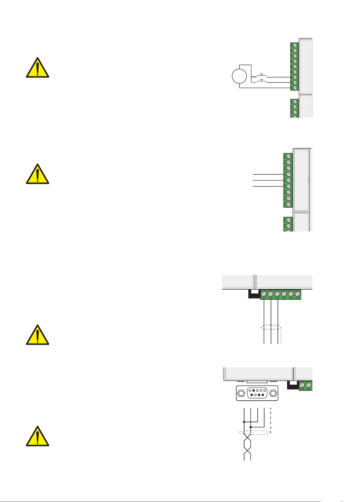
LOGIC OUTPUTS
The two opto-isolated relay outputs are of the type with normally
open contacts.
The capacity of each contact is 24 Vdc, 100 mA max. The
output connection cable does not have to be channelled
with power cables. The connection should be as short as
possible.
The environment where the equipment is installed can normally be
subject to strong magnetic fields and electrical disturbances caused
by the machinery present, therefore it is advisable to adopt the
normal precautions in order to prevent them affecting the typical
signals of an electronic precision apparatus. (filters on the remote
control switches, diodes on the 24 VDC relays, etc.)

DAT 1400
1
9
V+ (10 kΩ min)
Ana-
mA+ (300 Ω max)
SHIELD
Page 9
ANALOG OUTPUT (OPTIONAL)
The transmitter provides an analogue output in current or voltage.
Analogue output in voltage: range from 0 to 10 Volt or from 0 to 5
Volt, minimum load 10KΩ.
Analogue output in current: range from 0 to 20 mA or from 4 to 20
mA. Maximum load is 300Ω.
Analog transmission can be sensitive to electromagnetic
interference, it is therefore recommended that the cables
are as short as possible and that they follow their own route.
To make the connection, use a suitable shielded cable, ma-
king sure to connect the shield to the ground in one of the two ends.
Caution: do not connect the analogue output to active devices.
USB DEVICE ( SPECIFICATION 2.0 COMPLIANT; FULL-SPEED 12 MBPS)
Use this communication port to directly interface a PC via a USB port.
Use a standard USB cable for the connection.
To connect the instrument via the USB device, you must install a driver
on the PC which is suitable for the operating system used.
For installation please follow the specific instructions.
FIELDBUS CONNECTIONS
As an alternative to the RS485 serial port some of the most common
fieldbuses are available. You can use a single fieldbus which must
be specified when ordering.
ETHERNET CONNECTION
On the lower left part of the instrument there is a RJ45 connector
for Ethernet.
Features:
Trasmission speed 10 Mbps
Network compatible with 10/100/1000 Base-T
TCP Ethernet protocols, Modbus/TCP, UDP, IP, ICMP, ARP
TCP server communication mode
LED indicators (2) Presence of Ethernet and communication/dia-
gnostics line
Buffer size 256 bytes
Connection Time-out Min 30 seconds - Max 90 seconds
Link Time-out (cable disconnected) 30 seconds

1 2 3 4 5 6 7 8
1 2 3 4 5 6 7 8
TX+
RX+
RX-
TX-
TX+
RX+
RX-
TX-
1TX+
2TX-
3RX+
6RX-
1 RX+
2 RX-
3 TX+
6 TX-
DIRECT ETHERNET CABLE
1 2 3 4 5 6 7 8
1 2 3 4 5 6 7 8
TX+
RX+
RX-
TX-
RX+
TX+
TX-
RX-
1TX+
2TX-
3RX+
6RX-
1 TX+
2 TX-
3 RX+
6 RX-
CROSSOVER ETHERNET CABLE
Page 10
PIN DESCRIPTION
1 TX+
2 TX-
3 RX+
4
5
6 RX-
7
8
To connect to the MASTER, use a standard twisted pair Ethernet
cable with RJ45 connector.
The RJ45 Ethernet connection cable has a variable maximum length,
depending on the type of cable. A common Cat5 shielded cable
can have a maximum length of about 180 m.
• You can connect the Ethernet communication port directly to the
PC, without having to go through other network devices (routers,
switches, hubs, LAN-bridge or the like), but special RJ45 cables must
be used, called “crossover.”
• Normally cables are the “direct” type and allow connection to
network devices such as routers or hubs, but not direct connection
to two PCs (even if there are
currently network cards with
auto-sensing technology, which
recognize the type of cable and
the type of connection, allowing
direct PC-PC connections as well
as using non cross-over cables).
• On side are diagrams of the
two types of cables mentioned
and their connection diagram.
ETHERNET / IP CONNECTION
Ethernet / IP is a real-time industrial protocol which is based on the
Ethernet network.
There are two RJ45 connectors to allow connection of multiple in-
struments in the same network.
Refer to the previous page for connection notes and warnings.
Features:
10 and 100 Mbit operation, Full and Half Duplex
Modbus-TCP server
Up to 128 bytes of I / O fieldbus in every direction.

IN OUT
Page 11
PROFINET CONNECTION
The Profinet connector is RJ45, the same as the Ethernet interface.
There are two RJ45 connectors to allow connection of multiple in-
struments in the same network.
Refer to the previous page for connection notes and warnings.
Features:
PROFINET IO Real Time (RT) communications
Modbus-TCP server
Up to 128 bytes of I/O fieldbus in every direction.
ETHERCAT CONNECTION
EtherCAT is a real-time industrial protocol which is based on the
Ethernet network.
EhterCAT The protocol requires that the RJ45 connectors have the
function of IN and OUT.
Putting more DAT1400 instruments in series, the MASTER will be
connected to the IN connector of the first DAT1400, whose OUT
connector will be connected to the IN connector of the next etc ...
Refer to the previous page for connection notes and warnings.
MAC ADDRESS IN INSTRUMENTS WITH INDUSTRIAL FIELDBUS
ETHERNET.
Instruments which install Hilscher modules with Industrial Ethernet
Protocol (Profinet, EthernetIP, EtherCAT, etc.) have a label under the
connectors, as shown.
This label shows the MAC address of the module (red box), the
identification number of the module (blue box) and a QR code
that contains the MAC address. The latter can be read using a
smartphone app for reading QR codes (eg. on Google Play store,
“QR Code Reader”).

DAT 1400
19
24
3
8
15
9 6
B_LINE
A_LINE
Page 12
PROFIBUS DP CONNECTION
Pin Signal Description
1 - -
2 - -
3 B line +RxD/+TxD, level RS485
4RTS Request to send
5 GND Ground (isolated)
6 + 5V Bus Output +5V termination (isolated)
7 - -
8 A line -RxD/-TxD, level RS485
9 - -
Housing Cable shield Internally connected to protective
earth according to Profibus
specification
For connection to the Profibus Master, use a standard Profibus cable.
The typical impedance of the cable should be between 100 and
130 Ohms (f> 100 kHz). The cable capacity (measured between
conductor and conductor) should be less than 60 pF / m and the
minimum cable cross section should not be less than 0.22 mm2
In a Profibus-DP network, you can use either cable type A to type B
cable, depending on the required performance. The following table
summarizes the features of the cable to be used:
Specification Type A Cable Type B Cable
Impedance from 135 to 165 ohm
(f = 3 – 20 MHz)
from 100 to 300 ohm
(f > 100 kHz)
Capacity < 30 pF/m < 60 pF/m
Resistance < 110 ohm/km -
Conductor cross
section
> 0,34 mm2> 0,22 mm2
The following table shows the maximum length of the wires line with
cable type A and type B, function of the different communication
speed required:
Baud rate
(kbit/s) 9.6 19.2 187.5 500 1500 3000 6000 12000
Cable A lenght
(m) 1200 1200 1000 400 200 100 100 100
Cable B lenght
(m) 1200 1200 600 200 - - - -
For a reliable operation of the Fieldbus, should be used a line ter-
mination at both ends.
In the case of multiple DAT 1400 instruments, use the line termination
at only one instrument.
For configuring the instrument, the GSD file is available (hms_1810.
gsd) that must be installed in the master.

DAT 1400
19
24
2
3
1 5
6 9
7
CAN_L
CAN_H
Female
Male
Page 13
CANOPEN CONNECTION
Pin Signal Description
2 CAN_L CAN low bus line
3 CAN_GND
7 CAN_H CAN high bus line
CANopen is an higher-layer communication protocols based on a
CAN seria bus system.
For the connection using a cable with a twisted pair differential and
common return in accordance with ISO 11898. The length of the
bus is limited by the speed of communication chosen according to
the following table:
Bit Rate Max. Bus lenght
1 Mbit/sec 25 m
500 Kbit/sec 100 m
250 Kbit/sec 250 m
125 Kbit/sec 500 m
<=50 Kbit/sec 1000 m
The CAN line must have the resistance of 120Ω termination.
The reference CAN_GND must be connected to earth at one point
of the line.
The cable can not be channeled with power cables.
For the configuration of the card is available ESD file that must be
installed in the master.

DAT 1400
Page 14
FRONT PANEL OF THE INSTRUMENT
The DAT 1400 has a 6-digit lit display, 4 status LEDs and four keys with corresponding LEDs for con-
firming pressing of the key.
In operating mode, the display shows the weight and the LEDs indicate the status of weight and theset-
points.
The set-up parameters are easily accessed and modified using the three buttons on the front to select,
edit, confirm and save the new settings.
DISPLAY
The 6-digit display normally shows the weight on the scale. According to the various programming
procedures, the display is used for programming the parameters to be stored in the memory, i.e. the
messages that indicate the type of operation in progress and, therefore, help the Operator to manage
and program the instrument.
STAND-BY FUNCTION
The display can take on the stand-by mode, during which time the display brightness is reduced and
the keypad is locked. All other functions of the instrument are up and running.
See the paragraph on the activation / deactivation of the stand-by mode.
LED INDICATORS
To the left of the display there are 4 LED indicators:
1 State of the logic output 1 (ON = closed contact OFF = open contact)
2 State of the logic output 2 (ON = closed contact OFF = open contact)
NET The displayed value is the net weight
> < indicates the condition of stable weight.
Next to each button is also a LED that indicates when the button is pressed.

Page 15
USING THE KEYPAD
The instrument is programmed and controlled via the keypad consisting of 4 keys, all with dual function.
The selection of one of the two key functions is automatically established by the instrument based on
operation in progress. In general, the programming menus are managed using keys and keys to
scroll through the items; the to access the relevant submenu or programmable setting, whereas key
is used to exit the menu or go back to the higher level.
You can also use the keyboard by sliding your finger from left to right and back again as with a regular
smartphone.
SYMBOL DESCRIPTION
J
Short press on the single key. The corresponding LED will flash briefly
J
Long press on a single key. The corresponding LED will flash briefly and then
lights up until released.
The red LED at each key signals its activation.
KEY FUNCTIONS DURING WEIGHT DISPLAY
Access to the set points value programming menu
Display selection (gross weight, net weight).
(Press and hold) Weight / peak display selection
Resetting the displayed value (gross weight, net weight or peak).
Sending the weight string via the serial line.
(Press and hold) Access to quick set-up menu.
+
or
(Press for 3 sec) Access to set-up menu.
(Press for 6 sec) Access to set-up menu.

Page 16
KEY FUNCTION DURING THE PROGRAMMING MENU NAVIGATION
J
It selects the next menu.
J
It selects the previous menu.
J
It exits the programming menu or returns to the upper level.
J
It accesses the relative sub-menu or programming or confirms the selected
parameter.
KEY FUNCTION DURING SETTING OF THE NUMERICAL VALUES
J
It increases the value of the selected digit.
J
It decreases the value of the selected digit.
J
It selects the most-right digit.
J
It resets all the digits.
J
It ends composition and saves the value.
J
It exits without saving the changes.
KEY FUNCTION WHILE SETTING SUGGESTED VALUES
J
It selects the next value.
J
It selects the previous value.
J
It confirms and stores the displayed value.
J
It exits without saving the changes.
Pressing the key always results in a return to the previous menu.

Page 17
KEYBOARD LOCKING/UNLOCKING FUNCTIONS
OPERATION DESCRIPTION
J
+
Keyboard Lock - The keys are disabled until released. The display
goes into low power mode. The instrument is locked by simultaneously
pressing the ZERO + PRG keys for 5 seconds. By switching the instrument
on and off the instrument automatically unlocks.
J
+
Keyboard Unlock - By simultaneously pressing the ZERO + PRG keys for
5 seconds, the keys are reactivated and the brightness of the display
returns to standard.
EXITING THE CONFIGURATION MENU
Press the key to return to the main menu. Press the key again . “StorE?”is displayed.
Keep the key pressed until the message “sEtUP” appears. Press the key. to return to
the weight display.

Page 18
INFO DISPLAY
PdAt01 When the instrument is switched ON, a display test is run followed by the identifica-
tion code and then the version of the software, in that order. These codes are to be
cited when requesting assistance
When is not in progress a programming procedure, the display shows the weight measured in kilograms.
Under certain conditions, the following messages are reported:
NOTIFICATION OF ERRORS
In operating mode, the following error codes may appear on the display.
Fixed message
P <picco> Display of peak value.
rENotE Communication with “Optimation” PC utility software.
ϩϩϩϩϩϩ Overload. The load applied to the load cells exceeds by over 9 divisions the maximum
capacity of the weighing system.
O-L Signal that the load cells are absent or outside of the measuring range mV/V.
Flashing message, alternating with the weight measured.
No CAL Calibration weight not performed)
No CoN Fieldbus network disconnected
E-F.buS Fieldbus interface absent or not working.
This manual suits for next models
7
Table of contents
Other Pavone Systems Transmitter manuals


