Jetion solar JTxxxSFb series User manual

Installation Manual
Visionary green energy

Installation Manual
Please read this manual carefully before installation,and keep it for future reference.
Introduction
• JetionSolarPhotovoltaicmodulesconsistofcrystalline
siliconsolarcells,hightransmissionandlowirontoughened
glass,anti-agingEVAandhighameresistantbacksheet,and
anodizedaluminumalloyframe.
• JetionmodulesarequaliedfornationalstandardIEC
61215.2andIEC61730,whichhavepassedexamination
oftheauthorisedtytestcenter.Jetionmodulescanbeused
inroofsolarsystems,PVstations,communicationstations,
petrol,ocean,meteorological,trafcandPVbuildingsetc.
• Wearecommittedtoprovidingtechnicalandinstallation
supportforourcustomersworldwide.
• ThisInstallationManualisapplicabletotheinstallation
ofthefollowingJetionmodules:
JT***SFa/bJT***SAa/bJT***SBa/b
JT***SFcJT***SEcJT***SDcJT***SCcJT***SAc
JT***PFeJT***PEeJT***PDeJT***PCeJT***PAe
JT***SAa/b(Black)JT***SDc(Black)JT***SCc(Black)
Notes: 1.JT***SFa/bisusedhereasanexample.
2.“***”istheratedpoweroftherelatedJetionmodule.
• Thismanualcontainsimportantinformationregardingthein
stallation,safehandlingandmaintenanceofPVmodules
madebyJetion.
• Allinstructionsshouldbereadandunderstoodpriorto
installingthemodules.Theinstallershouldconformto
allrequirementsinthismanual.Theappropriatelocalstan-
dardsandregulations,constructionrulesandsafetyinst-
ructionsshouldalsobefollowedduringinstallation.Allwork
onaPVsystemmustbecarriedoutbyappropriatelyqualed
engineers,whomustbefamiliarwiththemechanicaland
electricalrequirementsforsuchaPVsystem.
Disclaimer of liability
• Theinstallation,handlinganduseofJetionmodulesarebey-
ondcompanycontrol.Therefore,Jetionassumesnores-
ponsibilityforloss,damage,injuryorexpenseresultingfrom
improperinstallation,handling,useormaintenance.
• Jetionreservestherighttoupdatetheproduct,specications
orthisInstallationManualwithoutpriornotice.
1) Certificates requests
1.1) IEC 61730
JetionmodulesaredesignedtofulllthecriteriaofApplica-
tionclassArequirementsaccordingtoIEC61730-1.
ModulesratedforuseinapplicationclassAmaybeusedin
systemsoperatingatgreaterthan50VDCor240W,where
generalcontactaccessisanticipated.Modulesqualiedfor
safetythroughIEC61730-1andIEC61730-2withinapplica-
tionclassAareconsideredtomeettherequirementsfor
safetyclass.
1.2) UL
• Theelectricalcharacteristicsarewithin+/-10%oftherated
valuesofIsc,VocandPmpundertestconditions(irradiance
of100mW/cm2,AM1.5spectrum,andcelltemperatureof
25°C).
• Thestand-offheightshouldbeatleast100mm(3.94in),and
therecommendedstand-offheightis115mm(4.53in).If
othermountingmeansareemployed,thismayaffectthe
ListingForFireClassRatings.
• ThemoduleshavebeenevaluatedbyULforamaximum
positiveornegativedesignloadingof30lb/ft²(146.5kg/m²).
• WiringmethodsshouldbeinaccordancewiththeNEC.
• ForinstallationinCanada,theinstallationshallalsobein
accordancewithCSAC22.1,safetyStandardsforElectrical
Installations,CanadianElectricalCode,Part1.
2) Installation requirements
2.1) Installation environment requirements
•Avoidshading:
Evenifthesmallestlocalshelter/shadow(suchasdustdepo-
sition)willalsodecreasetheoutputpower.
•Adequateventilation:
Hightemperatureofthemodulemayreducetheperfor-
manceandoutputpowerofthemodule.Goodventilation
caneffectivelyavoidtheoverheatingofPVmodules.
• Others:
- Donotinstallthemodulenearinammablegas(suchas
gasstation,gastanketc.)
- Donotinstallthemodulenearnakedameorammable
materials.
- Donotinstallthemoduleinalocationwithpotentialforextre-
mesandanddustdamage.
- Donotinstallthemoduleinalocationwithextremeair
pollution,suchaschemicalvapors,acidrain,and/orsoot.
- Donotexposethemoduletoalasersource.

- Donotinstallthemoduleinalocationwithextremehailand/
orsnow.
- Donotinstallthemoduleinalocationwhereitcouldbe
immersedinwaterorcontinuallyexposedtowaterfroma
sprinklerorfountain.
- Donotinstallthemoduleinamarineenvironmentand/or
areawheresaltywindhitdirectly.Itisrecommendedthatthe
modulebeinstalledatleast500mfromthesea.
- Environmenttemperature-20°Cto40°C.
- Operatingtemperature-40°Cto85°C.
2.2) Orientation and tilt for modules installation
• Solarmodulesproducethemaxpowerwhentheyare
pointeddirectlyatthesun.Inordertoachievemaximum
annualyield,optimumorientationandtiltofPVmodulesis
necessary.Themodules,whichconnectedinasystem,must
beinsameorientationandtilt,otherwise,itwilllosethepow-
erbecauseofthedifferencesofsunshineradiation.
• Themodulesmustbefacingthenorthinthesouthhemis-
phere,andfacingsouthinnorthhemisphere.
• Foroff-gridinstallationswheretheJetionmodulesareat-
tachedtoapermanentlystructure,theJetionmodules
shouldbetitledforoptimumwinterperformance.Asarule,
ifthesystempowerproductionisadequateinwinter,itwillbe
satisfactoryduringtherestoftheyear.Themoduletiteangle
ismeasuredbetweenthesolarmodulesandtheground.
Fig.1: ModuleTiltAngle
RECOMMENDEDTILTANGLESFORAFIXEDSYSTEM
SITELATITUDEINDEGREES FIXEDTILTANGLE
0°to15° 15°
15°to25° SAMEASLATITUDE
25°to30° LATITUDE+5°
30°to35° LATITUDE+10°
35°to40° LATITUDE+15°
40°+ LATITUDE+20°
Table1: ModuleTiltAngle
2.3) Materials requirements
• Supportstructure
Thesupportstructureofthemoduleismadeofabrason
proof,corrosionresistantandUVresistantmaterialswhich
correspondstotheappropriatestructuralrequirements.The
mountingstructureandthemoduleattachmentsmustbe
designedinaccordancewiththelocalwindandsnowloads.
• Bypassdiode
Partialshadingofanindividualmodulecancauseareverse
voltageacrosstheshadedmodule.Currentisthenforced
gothroughtheshadedareabytheothermodules.Whena
bypassdiodeiswiredinparallelwiththeseriesstring,the
forcedcurrentwillowthroughthediodeandbypassthe
shadedmodule,therebyminimizingmoduleheatingandarray
current losses.
• Supportstructure
Inasystemthatusesabattery,blockingdiodesaretypically
placedbetweenthebatteryandthemoduleoutputtoprevent
batterydischargeatnightandrainyweather.Diodesthatare
usedasblockingdiodesmusthavea:
a)RatedAverageForwardCurrent[[IF(AV)][abovethemaximum
systemcurrentathehighestmoduleoperatingtemperature.
b)RatedRepetitivePeakReverseVoltage[(VRRM)[abovethe
maximumsystemvoltage[(Vmax)[atthelowestmodule
operatingtemperature[(IEC:[Vmax=1000V;[UL:[Vmax=600V).
• Battery
Whensolarmodulesareusedtochargebatteries,thebattery
mustbeinstalledinamannerwhichwillprotecttheperfor-
manceofthesystemandthesafetyofitsusers.Thebattery
shouldbeawayfromthemainowofpeopleandanimal
trafc.Selectabatterysitethatisprotectedfromsunlight,
rain,snow,debris,andiswellventilated.Mostbatteries
generatehydrogengaswhencharging,whichisexplosive.
Donotlightmatchesorcreatesparksnearthebatterybank.
Whenabatteryisinstalledoutdoors,itshouldbeplacedin
aninsulatedandventilatedbatterycasespecicallydesigned
forthepurpose.
• Cableandothercomponents
a)Ensurethatallcomponentsmeettherequirementsofthe
system´smaximumvoltage,current,moistureandtempera-
turewhentheyareexposedtosunlight.Werecommended
thatallwiringandelectricalconnectionscomplywiththe
appropriatenationalelectricalcode.
b)Undernormalcondition,aphotovoltaicmoduleislikelyto
experienceconditionsthatproducemorecurrentand/or
voltagethanreportedatstandardtestconditions.
Accordingly,thevaluesofIscandVocmarkedonthismodule
shouldbemultipliedbyafactorof1.25whendetermining
componentvoltageratings,conductorcurrentratings,fuse
sizesandsizeofcontrolsconnectedtothePVoutput.Refer
tosection690-8oftheU.S.NationalElectricCodeforan
additionalmultiplyingof1.25whichmaybeapplicable.
c)Onlycableswithoneconductoraretobeused.
Module
Sunlight
Tilt Angle
Horizontal
d)Theareaofthecablematedwiththeconnectorisre-
commendedtobe4~6mm²,length:1000mm,tempera-
turerange:-40[to90.Themaximumseriesfuse[IMax.Series
fuse[(Mono-125:[IMax.Seriesfuse=10A[Mono-156&Poly-156
IMax.Seriesfuse=15A)[.
2.4) The requirements for different types of mount
•Groundmount
Selecttheheightofthemountingsystemtopreventthe
lowestedgeofthemodulefrombeingcoveredbysnowfora
longtimeinwinterinareasthatexperienceheavysnowfalls.
Inaddition,assurethelowestportionofthemoduleisplaced
highenoughsothatitisnotshadedbysandandstone
drivenbywind.
•Roofmount
a)Wheninstallingamoduleonarooforbuilding,ensurethatit
issecurelyfastenedandcannotfallasaresultofwindor
snowload.
b)Themodulesaresupportedparalleltosurfaceofthebuilding
wallorroof.Clearancebetweenthemoduleframesand
surfaceofthewallorroofisrequiredtopreventwiringdama-
geandtoallowairtocirculatebehindthemodule.
Thestandoffheightshouldbeatleast100mm[(3.94in).The
recommendedstand-offheightis115mm[(4.53in).[
c)Theroofinstallationofmodulesmayaffectthereproofper-
formanceofbuildingstructure.
d)ThemodulesmustbeinstalledontoaClassiedRoong
system.ThemodulesareClassC.Youcanmountthemover
aClassC,BorAroof.Theamountofareathemodules
covermaydegradetheroof‘soriginalreratinginsomeloca-
tions.Donotinstallmodulesonarooforbuildingduring
strongwindsincaseofaccident.
•Polemount
Wheninstallingamoduleonapool,chooseapoleand
modulemountingstructurethatshouldwillwithstandantici-
patedwindsforthearea.
3) Mounting Methods
Topreventbending,vibration,mechanicalstressor
warpage,mountthemoduleontoaatcontactsurface.The
minimaldistancebetweenmountedmodulesshouldbeno
lessthan20mm.Useallthemountingpointsprovidedand
avoiddirectcontactbetweenglassandmetal[(e.g.mounting
rails).,
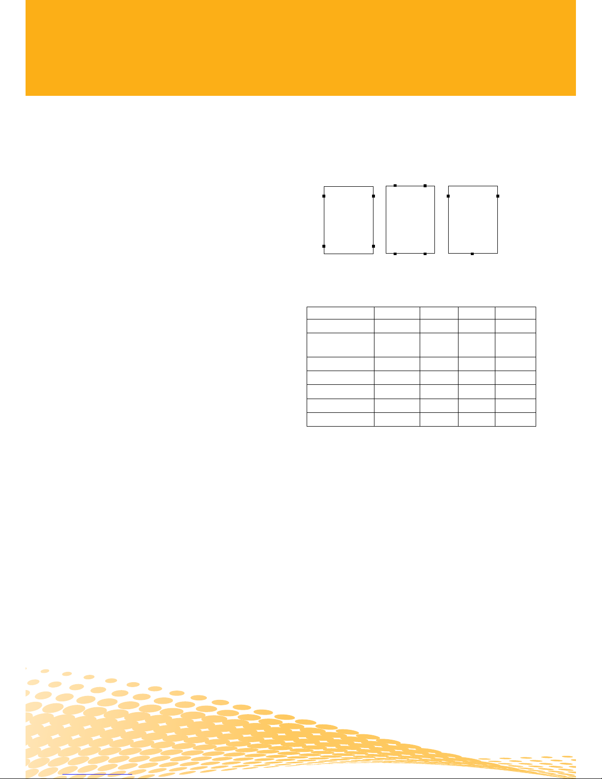
•Option1:ClampingMounting
Theclampsmustnotoverlaptheglassorshadethemodule
surface,ordistorttheframe.Recommendedtorqueis5Nm.
Fig.2
ModuleType Frame Type1 Type2 Type3
JT***SFa/b 30mm
JT***SAa/b
JT***SAa/b(Black) 40mm
JT***SC-Fc 40mm
JT***SC-Dc(Black) 40mm
JT***PC-Fe 40mm
JT***PAe/JT***SAc 45mm
JT***SBa/b 45mm
Table2
Notes:
1)JT***SFa/bisusedasanexample.
2)Where“***”istheratedpoweroftheJetionmodule.
3)““indicates5400paavailable;““indicates2400pais
available;““indicatesnoallowed.
4)Differentframeheightshouldchooseappropriateclampand
bolt.
5)MechanicalloadtestperformedaccordingtoIEC
standard,notapplicableforULproducts.
Type 1 Type 2 Type 3
Standard Mounting Short Side Mounting Triangle Mounting
FringeModules
Installation
MountingRail
Clamp
JT***SFa/b
JT***SAa/b
JT***SAa/b(Black)
JT***SBa/b
JT***PFe/JT***SFc
JT***PEe/JT***SEc
JT***PDe/JT***SDc/
JT***SDc(Black)
JT***PCe/JT***SCc/
JT***SCc(Black)
JT***PAe/JT***SAc
Mono
Mono
Mono
Poly/Mono
Poly/Mono
Poly/Mono
Mono
Poly/Mono
Mono
Poly/Mono
4x9
6x12
8x12
4x9
6x8
6x9
6x10
6x12
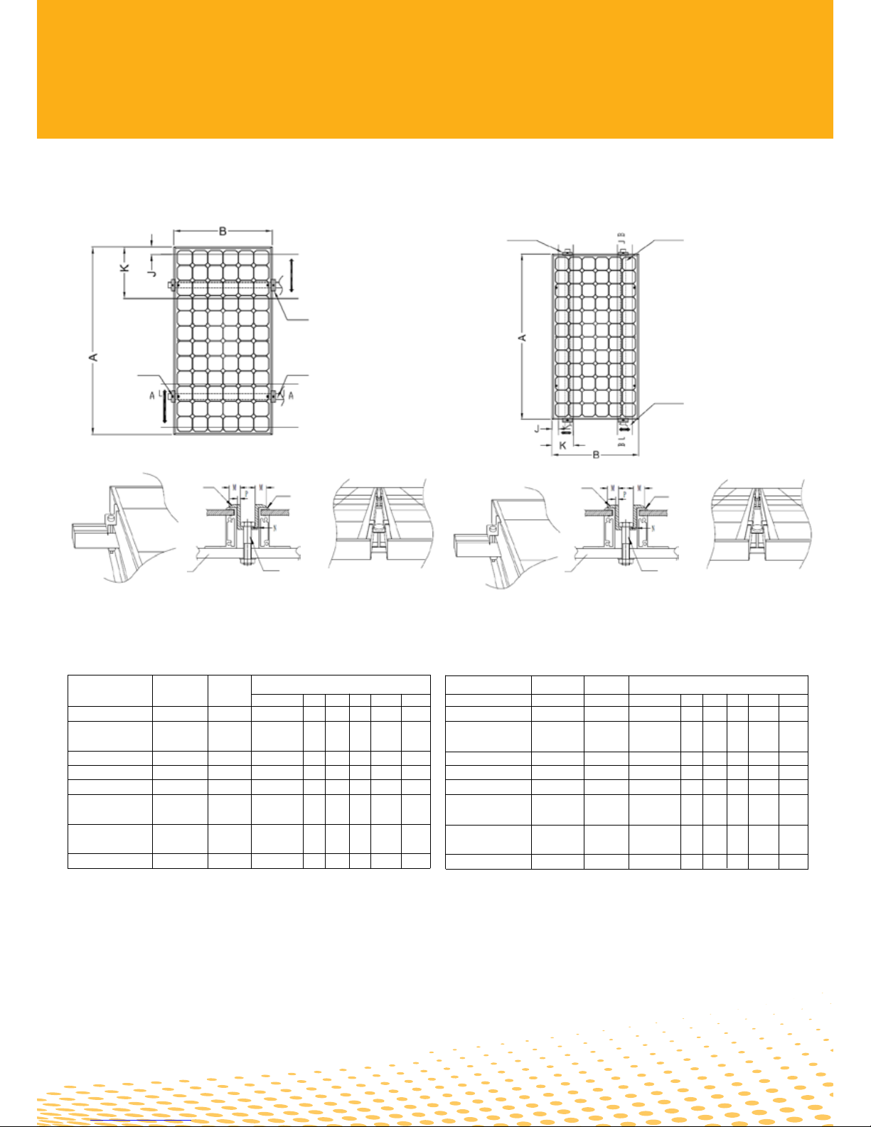
•Type1:StandardMounting
Fig.3
ModuleTypeCellTypeCellDimensions(mm)
Quantity AxBJKMNP
Table3(Foryourinformation)
Notes:
1)JT***SFa/bisusedasanexample.
2)Where“***”istheratedpoweroftheJetionmodule.
3)Dimension„N“representsthedistancebetweenclampandframe.
4)Dimension„P“representsthethicknessofclamp.
Themovementofthe
mountingrailandthe
clampscenter-lineare
recommendedtobe
withintheblackarrow
area.Pleasendspecic
datafromTable3.
MountingRail
M8Screw
MiddleModules
Installation
Frame(longside)
200
200
200
200
200
200
200
200
1195×541
1580×808
1580×1069
1482×676
1324×992
1482×992
1655×992
1956×992
50
50
50
50
50
50
50
50
12
12
12
12
12
12
12
12
0.5~2
0.5~2
0.5~2
0.5~2
0.5~2
0.5~2
0.5~2
0.5~2
2.5~3
2.5~3
2.5~3
2.5~3
2.5~3
2.5~3
2.5~3
2.5~3
M8Screw
MiddleModules
Installation
Frame(longside)
MountingrailClamp
Themovementofthe
mountingrailandthe
clampscenter-lineare
recommendedtobe
withintheblackarrow
area.Pleasendspecic
datafromTable4.
FringModules
Installation
•Type2:ShortSideMounting
Fig.4
ModuleTypeCellTypeCellDimensions(mm)
Quantity AxBJKMNP
Table4(Foryourinformation)
Notes:
1)JT***SFa/bisusedasanexample.
2)Where“***”istheratedpoweroftheJetionmodule.
3)Dimension„N“representsthedistancebetweenclampandframe.
4)Dimension„P“representsthethicknessofclamp.
200
200
200
200
200
200
200
200
1195×541
1580×808
1580×1069
1482×676
1324×992
1482×992
1655×992
1956×992
50
50
50
50
50
50
50
50
12
12
12
12
12
12
12
12
0.5~2
0.5~2
0.5~2
0.5~2
0.5~2
0.5~2
0.5~2
0.5~2
2.5~3
2.5~3
2.5~3
2.5~3
2.5~3
2.5~3
2.5~3
2.5~3
JT***SFa/b
JT***SAa/b
JT***SAa/b(Black)
JT***SBa/b
JT***PFe/JT***SFc
JT***PEe/JT***SEc
JT***PDe/JT***SDc/
JT***SDc(Black)
JT***PCe/JT***SCc/
JT***SCc(Black)
JT***PAe/JT***SAc
Mono
Mono
Mono
Poly/Mono
Poly/Mono
Poly/Mono
Mono
Poly/Mono
Mono
Poly/Mono
4x9
6x12
8x12
4x9
6x8
6x9
6x10
6x12

•Option2:BoltingMounting
Eachmoduleshouldsecuretheframesofmoduletosup-
portingstructurethroughatleast4mountingholes(corres-
pondingtothemountingrail2and3).Forhighwindand
snowloads,8holes(correspondingtothemountingrail1to
4)shouldbesecured.Themoduleframemustbeattached
tothemountingrailsusingM8corrosion-proofscrews
togetherwithspringwashersandatwashers.Recommen-
dedtorqueis5Nm.Usetheexitinginstallationholesinstead
ofdrillingadditionalholesforinstallation(Drillingholesis
againstthereliabilityandwarrantyofJetionmodules).Please
usecorrosion-resistantinstallationandattachmentmaterials.
Fig.5
Mountingrail1
Mountingrail2
Mountingrail4
Mountingrail3
8-[ 9×14
Nut
Mountingrail
M8srew
960
1300
1300
1100
1044
1100
1225
1676
1195×541x30
1580×808x40
1580×1069x45
1482×676x40
1324×992x40
1482×992x40
1655×992x40
1956×992x45
660x508
800x758
800x1019
700x626
544x942
700x942
725x942
1176x942
JT***SFa/b
JT***SAa/b
JT***SAa/b(Black)
JT***SBa/b
JT***PFe/JT***SFc
JT***PEe/JT***SEc
JT***PDe/JT***SDc/
JT***SDc(Black)
JT***PCe/JT***SCc/
JT***SCc(Black)
JT***PAe/JT***SAc
Mono
Mono
Mono
Poly/Mono
Poly/Mono
Poly/Mono
Mono
Poly/Mono
Mono
Poly/Mono
4x9
6x12
8x12
4x9
6x8
6x9
6x10
6x12
ModuleTypeCellTypeCellDimensionsMountingHoleMountingHole
Quantity AxBxC(mm) E (mm) GxF(mm)
Table5
Notes:
1)JT***SFa/bisusedasanexample.
2)Where“***”istheratedpoweroftheJetionmodule.
4) Grounding
• Toavoidtheriskofelectricalshockorre,themoduleframe
shouldbegroundedbeforetheelectricalconnectionofthe
modulesisoperated.
• TheframeshallbegroundedinaccordancewithNECArticle
250[USA[orCECinCanada.
• Foranadequateground,thegroundinghardwareshould
penetratetheanodizationlayer.
• OnlyULlistedcomponentsshouldbeusedforgrounding.
• Jetionrecommendsusingthefollowingcomponentsorequi-
valents.
1 StainlesssteelboltM4x30
2 StainlesssteelnutM4
3 StainlesssteelspringwasherM4
4&6StainlesssteelatwasherM4
5 Stainlesssteellock-toothedwasherM4
7 StainlesssteelcupwasherM4
8 Groundingwire
Fig.6
Washer

ModuleTypeCellTypeCellDimensionsMountingHoleMountingHole
Quantity AxBxC(mm) E (mm) GxF(mm)
• Attachaseparateconductorasgroundingwiretothe4mm
diametergroundingholeswithasetofM4bolt,cup
washer,atwasher,lock-toothedwasher,springwasherand
nut.
• Exposedcopperofthegroundingwireshallnotcontactsthe
moduleframeincaseofcorrodingtheframe.
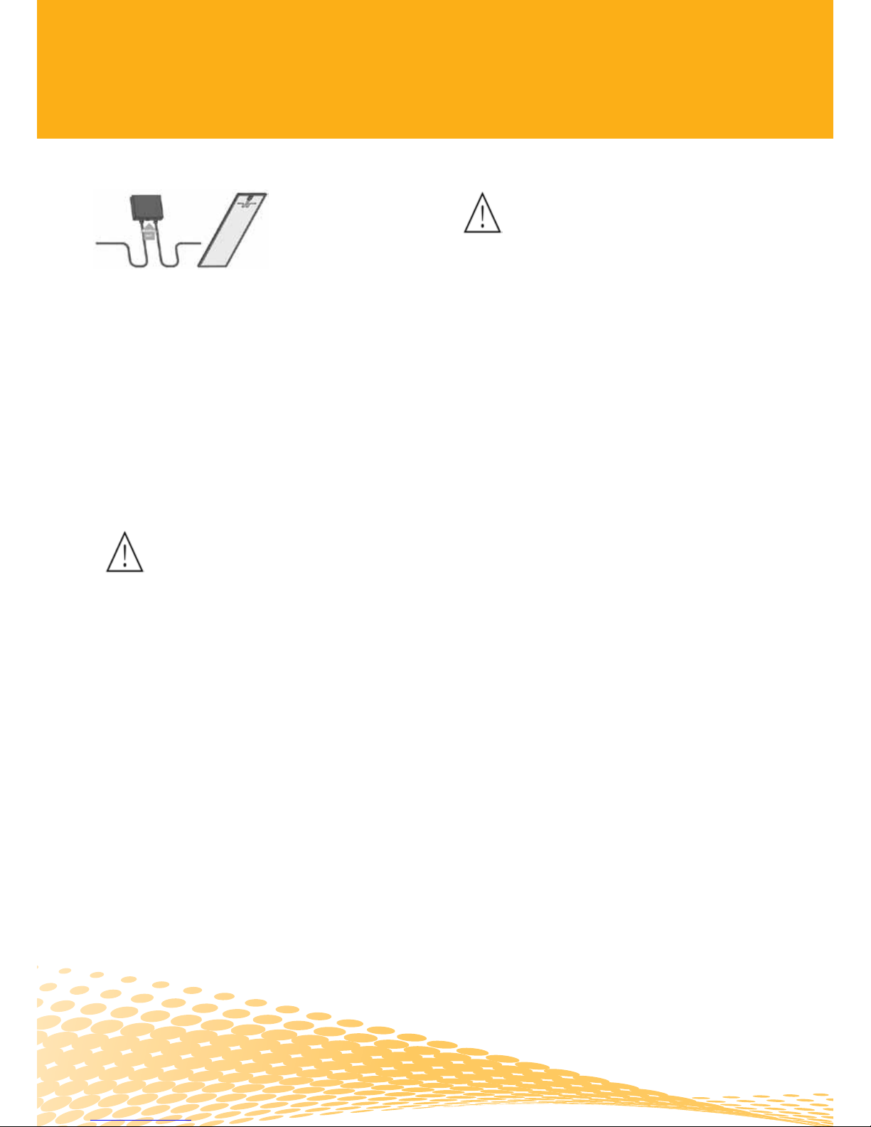
5) Wiring
For the wiring, pay attention to:
• Tominimizetheriskofindirectlightingstrike,avoidforming
closedloopswhendesigningthesystem.Checkthatwiring
iscorrectbeforestartingthegenerator.Ifthemeasuredopen
circuitvoltage(Uoc)[andshort-circuitcurrent[(Isc)different
fromthespecications,theremaybeawiringfault.
• JetionmodulesusetheJ-Box,onthebacksideofthemodule,
isweatherproofandisdesignedtobeusedwithstandard
wiringorconduitconnections.Wiringmethodsshouldbein
accordancetotheNEC(NationalElectricalCode).Bypass
diodesandcableclampsareincludedwitheachmodulewhen
shippedfromthefactory.
• Usemodulesofthesamecongurationsinthesamesystem.
Whenconnectedinseries,allmodulesmusthavethesame
current.Whenconnectedinparallel,themodulesmustallhave
thesamevoltage.Thequantityofmodulesconnectedshould
matchthevoltagespecicationsofthedevicesusedinthe
system.Themodulesmustnotbeconnectedtogetherto
createavoltagewhichishigherthanthepermittedsystem
voltage.WhendesigningtheJetionsystem,pleasealways
takeintoconsiderationthevariationofthevoltageunder
differenttemperatures(pleasechecktherespectivetempera-
turecoefcientsofthemodules,theVocofthemoduleswillbe
risewhenthetemperaturedrops).
• Thenumberofmodulesinseriesandinparallelinasystem.
• Whileconnectingthemodulesinseries,thetotalvoltage
shouldbelessthanthemaximumsystemvoltageUmax[(IEC:[
Umax=1000V;[UL:[Umax=600V).
• Whileconnectingthemodulesinparallel,thetotalcurrent
shouldbelessthanthemaximumsystemcurrent.
6) Maintenance and Cleaning
• DonotchangethePVcomponentsoptionally(diode,junction
box,plugconnectors).
• Givenasufcienttilt(atleast15°C),itisnotgenerallyneces-
sarytocleanthemodules(rainfallwillhaveaself-cleaning
effect).Incaseofheavysoiling(whichwillresultinoutput
reductions),werecommendcleaningthemodulesusing
plentyofwater(fromahose)withmilddetergentandusing
agentlecleaningimplement(asponge).CAUTION[DON’T
USEDETERGENTSCONSISTINGOFABRASIVE,ACETONE
OROTHERCORROSIVEELEMENTS.Donotcleanthe
moduleswithcoldwaterduringthewarmerhoursoftheday
inordertoavoidcreatinganythermalshockthatmaybe
damagethemodule.
Dirtmustneverbescrapedorrubbedawaywhen
dry,asthiswillcausemicro-scratches.Werecommendthat
thesystemisbeinginspectedatregularintervals.
7) Checklists
• Allfasteningsaretightandsecureandfreeofcorrosion.
• Allcableconnectionsaresecure,tight,cleanandfreeof
corrosion.
• Cablesarenotdamagedinanyway.
• Checkingtheearthingresistivelyofmetals.
8) Warning
• Themaximumloadonthemodulemustnotexceed30lb/ft²
(146.5kg/m²).Toavoidexceedingthemaximumload,site-
specicliveloadssuchaswindandsnowshouldtakeinto
account.
• Werecommendthatthemaximumnumberofmodulesin
parallelshouldbenomorethan2.Whenmorethantwo
modulesorstringsareplannedtobeputinparallel,usestring
fuses.Thenumberofmodulesinserieshastobemade
accordingtothemaxsystemvoltageoftheinverterwhichis
beingused.HowevertheVocVoltageofallmodulesinseries
shouldneverexceedmorethan1000V.
• Theplugconnectorhasitsownpolarity.Makesurethatthe
connectionissafeandtight.Ensurethattheyareingood
electricalandmechanicalcondition.
• Theplugconnectorshouldnotreceiveexternalstress.
• Donotattempttodrillholesintheglasssurfaceofthe
modules.
• Donotdrilladditionalmountingholesintheframeofthe
modules.
• DonothoistthemodulethroughtheJ-Boxorcable.
• Neveruseamodulewithbrokenglassortornsubstrate.
Brokenmodulescannotberepairedandcontactwithany
modulesurfaceorframecanleadtoelectricalshock.
• Donotinstallorhandlemoduleswhentheyarewetorduring
theperiodofhighwind.
• Keepchildrenwellawayfromthesystemwhiletransporting
andinstallingmechanicalandelectricalcomponents.
• Donotstrikeorphysicallydamagethemodule.
• Avoidcuttinganddamagingtheframeandthefrontsideor
backsidesurfaceofthemoduleduringhandlingandinstallati-
on.
• Donotstandorsteponthemodule.
• Donotputextraobjectsonthemoduleincaseofglass
broken.
• TheJ-Boxmustbeonthehighersideofthemodulewhenitis
mounted.
• Donotdismantleordropthemoduleanddonotremoveany
attachednameplateorcomponentsfromthemodule.
• Donotbendortwistthemodule.
• Donotapplypaintoradhesivetomoduletopsurface.
• Donotusepointedorsharpobjectswiththemodule.
• Articiallyconcentratedsunlightshallnotbedirectedonthe
module.
• Precipitationcanrunoffthroughsmallopeningsonthe
backsideofthemodule.Makesurethattheopeningsare
notmaskedaftermounting.
• Donotwearingrings,watches,ormetaljewelryduringinstal-
lations.
9) Hazard Warnings
Danger of death from electric shock!
PVmodulesgenerateelectricityassoonastheyareexposedto
sunlight.Onemodulegeneratesasafe,extralowvoltagelevel,
butmultiplemodulesconnectedinseries(summingthevoltage)
orinparallel(summingthecurrent)representadanger.Thefol-
lowingpointsmustbenotedwhenhandlingthesolarmodules
toavoidtheriskofre,sparkingandfatalelectricshock.
•Donotinsertelectricallyconductingpartsintotheplugsor
sockets!
• Donottsolarmodulesandwiringwithwetplugsand
sockets!
• Exerciseutmostcautionwhencarryingoutworkonwiring
andsafetyequipment(useinsulatedtools,insulatedgloves,
etc.)!
• Donotusedamagedmodules!Donotdismantlemodules!
Donotmarkontherearofthemoduleusingsharpobjects!
• Exerciseutmostcautionwhenworkingonwiringandthe
inverter.Besurecarefullytofollowmanufacture’sinstallation
instructions!
Danger of death from arcing!
Modulesgeneratedirectcurrentwhenlightshinesonthem.An
electricarcmaybegeneratedwhenconnectorsareusedto
turnthecircuitonoroff.Wethereforerecommendedcovering
moduleswithalightproofclothduringinstallation.Whenbrea-
kingaconnectedstringofmodules(e.g.whendisconnecting
theDClinefromtheinverterunderload),alethallystrongarc
canoccur.
•Neverdisconnectthesolargeneratorfromtheinverterwhile
theinverterisconnectedtothemainsgrid—removethefuse
fromtheACsideontheinverterrst!
• Ensuretheconnectorsarecleanandhavenotbeenconta-
minatedandthattheelectricalconnectionandmechanical
jointaregood!

JTInstallationsguideen©JetionSolar|11/2011
Printedonenvironmentallyfriendlypaper.
JETION SOLAR EUROPE
JetionSolar(Europe)Ltd.
Industriering10
9491Ruggell
Liechtenstein
Phone: +4232653830
Fax: +4232653839
E-Mail:info@jetion.biz
www.jetion.biz
JETION SOLAR CHINA
JetionSolar(China)Co.,Ltd.
No.1011,ZhenchengRoad
Shengang,JiangyinMunicipality
JiangsuProvince214443
PeoplesRepublicofChina
Phone:+8651086687300
Fax: +8651086687315
E-Mail:marketing@jetion.com.cn
www.jetionsolar.com
JETION SOLAR USA
10900-ASouthCommerceBlvd
Charlotte,NC28273
Phone: +17049441069
Tollfree: 8006068569
Fax: +17049441080
E-Mail:[email protected]
www.JetionSolarUS.com
This manual suits for next models
19
Table of contents


