BayWa novotegra closed II User manual

I
Mounting instructions
novotegra for flat roofs
closed II / East-West II

II
TABLE OF CONTENTS
1Notes .............................................................................................................................. 1
2Maintenance of the mounting system.......................................................................... 3
3novotegra for tile roofs II............................................................................................... 3
4System components, tools and equipment................................................................. 4
4.1 Required for installation............................................................................................. 4
4.2 Installation system components –installation variants............................................... 5
4.3 Installation system components –optional................................................................. 6
5Installing the substructure............................................................................................ 7
5.1 Installing the base rails and support components....................................................... 7
5.2 Module installation, load redistribution and ballast..................................................... 8
5.3 Mounting versions.....................................................................................................10
6Warranty / product liability (exclusion).......................................................................14

1
1 Notes
Safety information
Mounting tasks may only be carried out by qualified and competent persons. During the work protective
clothing in accordance with the relevant national regulations and guidelines must be worn.
Mounting must be carried out by at least two persons to ensure help in case of an accident.
All relevant national and locally applicable health and safety regulations, accident prevention regulations,
standards, construction standards and environmental protection regulations as well as all regulations of the
employers’ liability insurance associations must be complied with.
The national regulations for working at height / on the roof must be complied with.
Electrical work must be carried out in compliance with the national and locally applicable standards and
guidelines and the safety rules for electrical work.
Earthing / equipotential bonding of the mounting system must be carried out in accordance with the
national and locally applicable standards and guidelines.
Categorisation into hazard classes
To alert the user of potential danger situations the hazard classes analogous to ANSI Z 535 are used. The
hazard class describes the risk if the safety information is not observed.
Warning symbol with signal word
Hazard class analogous to ANSI Z 535
DANGER! describes an immediate danger. If it is not
avoided, death or serious injury will result.
WARNING! describes a potential danger. If it is not avoided,
death or serious injury might result.
CAUTION! describes a potential danger. If it is not avoided,
light or minor injury might result.
NOTE! describes a potentially harmful situation. If it is not
avoided, the plant or objects in its vicinity might be damaged.
General information
After receipt the goods must be inspected for completeness using the accompanying delivery note.
BayWa r.e. Solar Energy Systems GmbH does not accept the costs, nor can we guarantee subsequent
express deliveries if missing material is only noticed during mounting.
Since our mounting systems are subject to continuous development, mounting processes or components
may change. Therefore, please check the current status of the mounting instructions on our website prior to
mounting. We are also happy to send you current versions upon request.
The mounting system is suitable for the attachment of PV modules with standard market dimensions. The
maximum permissible module width is 1.34 m.
The usability of the mounting system for the respective project must be checked for each individual case on
the basis of the roof cover / roof construction present.
The roof cover / roof construction must meet the requirements of the mounting system with regard to load
bearing capacity, support structure and condition.
Requirements for the material of the roof construction or roof cover:
Wooden components (rafters/purlins): min. strength class C24, no fungus infection or rot
Tensile strength Rm, min for trapezoidal metal: steel 360 N/mm²; aluminium 195 N/mm²

2
The load bearing capacity of the roof / roof construction (rafters, purlins, trapezoidal metal, number of
adhesive points, folded seams, etc.) must be checked by the user or a check be commissioned.
Physical building aspects concerning insulation penetrations (e.g. condensation) must be taken into
account by the user.
Notes on mounting
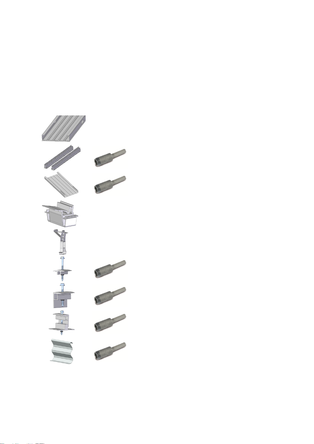
The components of the novotegra mounting system are intended exclusively for the attachment of PV
modules. Dependent on the roof type of the building the designated mounting system components must be
used.
A condition for the intended use of the novotegra mounting system is the mandatory compliance with the
specifications in these instructions regarding safety information and mounting.
In case of unintended use and non-compliance with the safety information and mounting instructions and
non-utilisation of the corresponding mounting components or use of third party components not belonging
to the mounting system any warranty and liability claims against the manufacturer are voided. The user is
liable for damage and resulting consequential damage to other components, such as PV modules, or the
building as well as personal injury.
The user must read the mounting instructions prior to mounting. Unresolved issues must be clarified with
the manufacturer prior to mounting. The mounting sequence in these instructions must be adhered to.
It must be ensured that a copy of the mounting instructions is accessible in the immediate vicinity of the
work on site.
The mounting specifications (module load, attachment, clamping areas etc.) of the module manufacturer
must be observed and complied with.
Prior to mounting the mounting system must be statically calculated with the loads to be assumed for the
building project in accordance with the national standards. Information relevant to mounting (e.g. roof hook
distance, lengths of bolts, overhang and protrusions) must be determined by the static calculation using the
design software Solar-Planit.de.
The permissible roof inclination for the use of the mounting system in accordance with these mounting
instructions is 0 to 60 degrees.
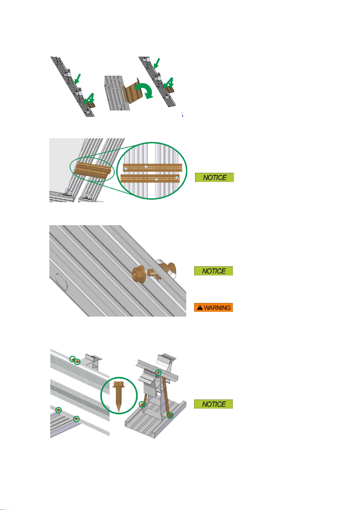
For each module two module support rails must be fitted symmetrically under the modules for the even
load introduction to the substructure.
The specified tightening torques must be adhered to and checked randomly on site.
Notes on static calculations
The mounting system must generally be statically calculated for each individual project using the design
software Solar-planit.de.
The static calculation only determines the load bearing capacity of the novotegra mounting system and also
takes account of the attachment to the building (rafters, purlins, trapezoidal metal etc.). The load transfer
within the building is not considered (customer static calculations).
The load bearing capacity of the mounting system components is determined on the basis of the planned
module layout and the underlying roof information (project data recording). Deviations from the planning on
site may lead to different results.
The load assumptions (load and roof division) are country-specific in accordance with the specifications of
the Eurocode load standards. The determination of the loads to be assumed for Switzerland is in
accordance with SIA 261.
The modules may not be fitted above the gable end, ridge and eaves (increased wind load). At the ridge
the modules may be fitted up to max. a theoretical horizontal line with the ridge tile and perfectly flush with
the gable end. In the eaves area the modules may reach to max. the end of the roof cover due to loads.
In case of an exposed building position (with wind load e.g. at the edge of a slope) or snow accumulation
(e.g. dormer or catchment grill) the specifications of the Eurocode load standards or SIA 261 (Switzerland)
must be taken into account by the user within his own responsibility. The design software does not consider
these cases.

3
The static calculation of the mounting system is based on the symmetrical placement of the modules on the
mounting rails at the longitudinal side of the modules for even load transfer into the substructure.
The results calculated with the design software, such as distances of the fasteners (e.g. roof hooks, hanger
bolts, saddle clamps etc.), rail lengths and number of fasteners (e.g. direct attachment on the trapezoidal
metal), overhang (e.g. rail and roof hook protrusions) and the other calculation notes must be considered
and complied with.
novotegra has been tested and certified by TÜV Rheinland:
2 Maintenance of the mounting system
The mounting system must be checked for stability and operation at regular intervals during the system
maintenance.
In addition to the visual inspection of the components and the roof cover for damage we recommend a
random inspection of the connections.
Removal is possible in reverse order in the work steps mentioned below.
The maintenance work must be carried out by a specialist company with proven experience in electrical
systems and work on mounting systems.
3 novotegra for tile roofs II
The contents of this installation manual describe the installation of the substructure on roofs with sheet or
bitumen waterproofing.
Depending on the roof seal material, separation and/or protection membranes may need to be added
between the roof seal and the substructure. This must be agreed upon directly between the company
installing the PV system, the building owner and the specialist roof sealing company.
The substructure is installed without penetrating the roof. The PV system is secured against wind suction
by providing ballast (e.g. suitable stones), based on the results of the wind tunnel tests for the system. The
required ballast is determined by BayWa r.e. Solar Energy Systems GmbH based on the project data
provided by the installation company. The ballast applies to the planned system; on-site deviations from
planning may lead to different results.
Protection against system sliding is verified based on a coefficient of friction of = 0.5. This value must be
checked by the installation company prior to installation. If the coefficient of friction is determined by the
installation company in advance, protection can be verified during planning using the determined value.
The system must be secured on site to prevent it from "creeping" due to expansion caused by temperature.
This can be achieved by installing suitable stop points on the roof surface or by anchoring to the parapet,
for example. The connection points on the building and building parts must be able to bear the forces
exerted.
General conditions to be observed in accordance with the wind tunnel test results:
- Roof incline 0 –5 degrees
- Flat roofs with and without parapet
- Distance from system to roof edge (without parapet) = 0.50 m
- Distance from system to parapet (inside edge) = 0.50 m
- Max module width = approx. 1.08 m max. module length = approx. 1.70 m
- Angle of installation (fixed) = 13°
- Distance between rows = 1.30 –2.40 m (closed II) respectively 2.15 –2.45 m (East-West II)
(distance between the front of a panel and the front of the one behind)

4
The installation system is designed for loads of up to 2.4 kN/m² (2,400 Pa). The modules are clamped on
the short frame side or, alternatively, on the long frame side in the corners (clamp surface 11 x 52 mm).
This requires approval from the module manufacturer for clamping on the short frame side or on the corner
of the long frame side. Any drainage openings on the module frame may not be blocked. This also applies
to the features provided for this purpose on the support components.
4 System components, tools and equipment
4.1 Required for installation
Figure
Tool
Component*
Product group
Base trough 150-30
Material: Aluminium
Profile rail
Base trough connector set 150-30 I
Material: Aluminium
Tool: Socket bit AF 8 mm
Rail connectors and
expansion joint
Base trough expansion joint 150-30
Material: Aluminium and V2A
Tool: Socket bit AF 8 mm
Rail connectors and
expansion joint
Base foot set
Material: Aluminium
Module elevation
Module support set 13°
Material: Aluminium
Module elevation
Flat roof mid clamp
Material: Aluminium and V2A
Tool: Socket bit AF 8 mm
Module elevation
Flat roof end clamp
Material: Aluminium and V2A
Tool: Socket bit AF 8 mm
Module elevation
Flat roof end clamp (short side)
Material: Aluminium and V2A
Tool: Socket bit AF 8 mm
Module elevation
Wind deflector 13° 1.85 m
Material: Aluminium
Tool: Socket bit AF 8 mm
Module elevation

5
Flat roof mounting screw chipless
Material: V2A
Tool: Socket bit AF 8 mm
Fastening equipment
Alu edge protector self-adhesive
Material: Aluminium
Seal parts and
protective devices
* The components vary depending on the requirements of the roof, the structural analysis and the choice of
components and may deviate from the images above.
Figure
Equipment
Use for tool
Application
Cordless
screwdriver
Bit Torx TX 40
Socket bit AF 8 mm
Component
connections, clamp
assembly
Torque key up
to at least
12 Nm
Socket bit AF 8 mm
Clamp assembly
Chopsaw
---
Cutting rails
Place / replace
tool base trough
150-30
For place / replace of base foot and
module supports set in the base
trough 150-30
Correct installation
4.2 Installation system components –installation variants
Figure
Tool
Component**
Product group
Module support set 13° East-West
Material: Aluminium
Module elevation
Support Brace 20x20x1.5 East-West
Material: Aluminium
Profile rail
Wind deflector 13° 1.85 m East-West
Material: Aluminium
Tool: Socket bit AF 8 mm
Module elevation
C-rail (base profile, base trough)
Material: Aluminium
Profile rail
Rail connector set
Material: Aluminium and V2A
Tool: Special lock nut AF 18 deep
Profile rail
PE pad 140 x 390 x 20 mm
Material: PE foam
** Required components for ballast distribution at system edge, depending on substructure construction.

6
4.3 Installation system components –optional
Image
Tool
Component***
Product group
Ballast trough
Material: Aluminium
Support and module
fastening
Connector profile C47 385 mm
Material: Aluminium
Tool: Socket bit AF 8 mm
Module elevation
Cable holder
Material: Plastic
Cable protection
Top cover base trough 150-30 3.00m
Material: Aluminium
Module protection
and rail top cover
Self-locking cable tie
Cable protection
Cable clip d = 10 mm
Cable protection
Grounding connector set AF 18
Material: V2A
Tool: Special lock nut AF 18 deep
Accessories and
optional components
Alu perforated tape 10,000 x 20 x 1
Material: Aluminium
Tool: Socket bit AF 8 mm
Accessories and
optional components
*** Optionally available installation system components, e.g. for improving the aesthetics of the system,
cable routing or earthing of the installation system.

7
5 Installing the substructure
Prior to installation, the module array must be measured out on the roof and the position of the modules
determined, taking into account any obstacles such as light domes or strips, fans or drains.
The individual installation steps of the system variant closed II (south facing) are described below.
References are made to mounting versions (MV) for the various design possibilities respectively to the
system variant East-West II. The associated work steps are described at the end.
5.1 Installing the base rails and support components
Arranging the base troughs
Install the base troughs centrally beneath the
module joint (MV 1).
Maximum module field size without measurements
(MV 4) for compensation of temperature-related
length expansions 17 x 17 m (Module field 10 x 10
with approx. 1.70 m row spacing)
Distance to adjacent module field: min. 50 mm
System edge / module joint:
eM= module length + 12 mm
Observe the accident prevention regulations when
sawing.
Connecting the base troughs
Push the ends of the base troughs tightly together,
push the connectors under the ridge on the base
troughs and screw together with two screws on
each side.
Maximum uninterrupted rail length approx.17 m,
then install expansion joint or disconnect the rail
(MV 4).
The base trough joints and base trough ends must
be covered using the self-adhesive edge protection
provided.
The distance between the base troughs in the joint
may not exceed 100 mm.
Installing the base foot
Insert the component into the base trough on one
side as shown and then click into the base trough.
The component may need to be screwed down,
depending on the wind load (MV 5). If a base foot is
located above a long hole, the foot must always be
secured with a screw.
Prior to installation, the position (installation axis) of
the components must be determined on the base
trough.
Depending on the existing conditions on site,
installation using the installation and removal tool is
recommended.
eM
eM
Edge eMjoint eMjoint

8
Installing module supports
Insert the component into the base trough on one
side as shown and then click into the base trough.
The component may need to be screwed down,
depending on the wind load or if its position is
above long hole (MV 5).
Installation module support East-West regarding
MV4.
Prior to installation, the position (installation axis) of
the components must be determined on the base
trough.
Depending on the existing conditions on site,
installation using the installation and removal tool is
recommended.
5.2 Module installation, load redistribution and ballast
Installing the module
Position the module on the base feet and then
place it on the module support set.
For notes regarding module installation for East-
West II, see MV 8.
Wire adjacent modules while installing them
Install the string cable first
Fastening the modules on the row end
Secure modules at the end of a row or at a break in
the row (light domes, fans, etc.) using the flat roof
end clamp (short side).
Push the clamping block of the module fastener
beneath the module, place the fastener on the
module and screw the drilling screw through the
bore hole.
Tightening torque max. 6 Nm.
The screw must not be overtightened!
Clamp on the short frame side.
Fastening the module to the module joint
Position the following module on the base foot or
module support. Determine the gap between the
modules (12 mm) by inserting the flat roof mid
clamp. Insert the module fasteners so that the
drilling screw is positioned in the bore hole on the
base foot or module support.
Tightening torque max. 6 Nm.
The screw must not be overtightened!
Clamp on the short frame side.

9
Connection rail
To reduce ballast on the southern (east-west) edge
or at breaks in the system (e.g. along light strips or
maintenance pathways), position the base trough
150-30 perpendicularly on the base trough as a
connection rail and secure with two screws on each
side. Extend using base trough connectors or
expansion joints at system breaks. Arrange the
expansion joints identically to the expansion joints
of the module supports. Cut the base troughs to
length if required.
The connection rail can be used to install the string
cable or to insert the required ballast. MV 10
applies if installing without connection rail.
Further rails can be used to redistribute load:
- C-rail 47, 71 and 95, base profile 6.12 m
Ballast
Place ballast in accordance with the ballast
planning into the base troughs after installing the
modules. The required ballast depends on the
system area and is specified in the ballast plan in
kg and/or number of stones. The ballast can be laid
out under, in front of or behind the module to
accommodate the required ballast. The choice of
ballast stones is done during installation, and the
dimensions are based on the height of the ballast.
For ballast installations using large amounts of
ballast, ballast troughs (MV 11) or additional base
troughs under the module are recommended (MV
6).
Installing the wind deflector
Guide the wind deflector over the round part of the
module supports and place on the base trough.
Install the adjacent wind deflector for the following
module with an overlap of at least 150 mm to the
first wind deflector.
Secure the wind deflectors to the base troughs with
two screws for each rail and to the round part of the
module support with one or two screws, depending
on the load to be borne (specifications in detail
plan).
The screw must not be overtightened!
> 150
5kg
10kg
23kg
5kg
10kg
23kg

10
5.3 Mounting versions
Explanation of the installation variants depending on the roof construction or design variants.
MV 1 –Flush base troughs on system edge
Alternatively, the first base trough at the system
edge / expansion joint must be installed flush with
the modules, the subsequent troughs must be
positioned centrally beneath the module joint.
Prerequisite: Flat roof end clamp (MV 2)
Approval module manufacturer
for module clamping
System edge / expansion joint:
eA= module length –69 mm
Module joint: eM= module length + 12 mm
MV 2 –Module fastening long side
Place the drilling screw from the flat roof end clamp
centred over the screw channel of the base foot or
module support and screw in.
Tightening torque max. 6 Nm.
The screw must not be overtightened!
Approval from manufacturer required for clamping
in the corner section of the long frame side.
MV 3 –Base troughs for cross drainage
If the base troughs 150-30 for cross drainage end
without PE pads, stick additional PE pad (1) onto
these troughs
Max. 100 mm. extension over PE-pad
Distance between PE pads: max. 610 mm
Shorten PE-pad to the required length if needed
MV 4 –Installation of expansion joints
in the base troughs
Push the base trough expansion joint centrally into
the adjacent base troughs. A gap of 50 mm must
remain between the ends of the rails. Screw the
expansion joints to the base troughs. On the
moving side, the two screws must be screwed into
the base trough so that they are centred in the
slots.
Do not install the expansion joint below a module.
Max. base trough length with the base trough
expansion joint approx. 34 m, plan for proper
expansion joints after this.
eM
Edge eAjoint eMjoint
eA
50
max. 610 mm
max. 100 mm
1

11
MV 5 –Securing the base foot / module
supports set
Depending on requirements, the base foot and
module support may need to be secured with
screws.
MV 6 –Mounting 3. Base rail
Depending on the ballast, a 3rd base trough may be
required for additional storage space. It should be
positioned midway between two base troughs in
accordance with the ballast plan. Secure the
module in addition to the clamps at the corners
using the flat roof end clamp on the long side (1)
Secure wind deflector with one screw at base
trough and module support
MV 7 –Module supports East-West
Regarding the occurring loads the module support
set of the East-West II system variant must be
installed with a single or a double leg.
Prior to installation, the position (installation axis) of
the components must be determined on the base
trough.
Depending on the existing conditions on site,
installation using the installation and removal tool is
recommended.
1
1

12
MV 8 –Installing the module –system variant
East-West II
Position the module on base feet and then place it
on the module support set. Install the modules of
one axis of a double row first.
Place ballast in accordance with the ballast
planning into the base troughs after installing the
modules.
After fixing the modules place the support brace on
the module support set and fix the support brace to
the module support set. Support brace joint
overlapping above the module support brace
Place ballast and install the modules on the other
side of the double row on the module support set.
Wire adjacent modules when installing them
Install the string cable first
MV 9 –wind deflector East-West
Wind deflector-module support (1):
Lay the wind deflector under the module. The
module and wind deflector should be fastened to
the support with flat roof end clamps (short side)
and attached to the base trough with two additional
screws.
Wind deflector-wind deflector (or edge) support (2)
Install the wind deflector East-West on the module
support set double as detailed in the section
‘Installing the wind deflector’ and attach it to the
base trough using two screws and to the module
support using one screw
MV 10 –Installation / ballast without connection
rail
The amount of required ballast at the system edge
increases if not using a connection rail. No load
redistribution is possible.
The adjacent modules must each be secured with
the flat roof end clamp in the corner of the long
frame side instead of with the flat roof mid clamp.
Tightening torque max. 6 Nm.
The screw must not be overtightened!
2
1

13
MV 11 –Ballast troughs
Using ballast troughs allows small or large-size
ballast to be securely inserted if required. The
ballast troughs must be mounted on the side of the
base troughs.
MV 12 –Installation of expansion joints in the
base troughs
Connect adjacent module fields with two connector
profiles. Secure the first rail profile (1) with two
screws on the left base trough and then secure the
second rail profile (2) on the right base trough.
Leave the loose end of the coupling profile
protruding over the edge (3).
The connector profile is only ever firmly secured to
a base trough
Distance between base troughs 50 mm
MV 13 –Attaching grounding connectors
Ground wire (according to national
specifications):
Remove grounding connector, remove clamping
disk. Push component through long hole in the base
trough. Push ground wire through the opening
(suitable for 6-10 mm) and attach the component
with the self-locking nut.
Ground wire tightening torque 20 Nm
On site, perforate the base trough for cross
drainage in the desired spot
The applicable standards and guidelines, e.g.
lightning protection standard, must be observed
MV 14 –Lightning current carrying capacity
measures
To ensure the lightning current carrying capacity of
the mounting system, securely fasten the supports
with screws. To do this, 4 or 3 mounting screws
without seal should be used. (South II or East-West
II variant). The East-West support is furnished with
the alu-perforated tape and should be screwed to
the module support head and both sides of the foot.
These actions shall be performed upon consultation
with and under consideration of the guidelines of an
approved electrician or lightning protection engineer
10kg
35kg
10kg
35kg
1
3
1
2

14
6 Warranty / product liability (exclusion)
In addition to the above-mentioned regulations and safety notices the applicable regulations and rules of
technology must be observed by the installing specialist company.
The installer is responsible for the dimensioning of the mounting system.
The installer is responsible for the connection of the interfaces between the mounting system and the
building. This also includes the tightness of the building envelope.
For flat roofs the roof insulation must be evaluated by the installer on site within his own responsibility
regarding the material of the sealing layer, resistance, ageing, compatibility with other materials, overall
condition of the roof insulation, need for a separating layer between the roof insulation and the mounting
system. The required and necessary measures or precautions for the protection of the roof insulation for
the mounting of the substructure of a PV system must be initiated by the installer with the aid of a specialist
tradesman where necessary. BayWa r.e. Solar Energy Systems GmbH does not accept liability for faulty or
inadequate measures and precautions for the protection of the roof insulation!
The installer must review the friction coefficient used in the calculation for the verification of the slip safety
of PV systems on flat roofs on site. Friction coefficients determined on site may be taken into account and
must be provided to BayWa r.e. Solar Energy Systems GmbH for the calculation. BayWa r.e. Solar Energy
Systems GmbH does not guarantee the correctness of the assumed values and is not liable for damage
due to the use of incorrect values.
The specifications of the module, cable and inverter manufacturers must be observed. If these contradict
the mounting instructions, always consult the BayWa r.e. Solar Energy Systems GmbH sales team before
mounting the novotegra mounting system or –in the case of components not supplied by BayWa r.e. Solar
Energy Systems GmbH –the manufacturer concerned.
During the preparation of the offers for novotegra by our sales staff the local conditions are not always
sufficiently known, which is why changes to the offered quantities may result during installation. These
changes relate mainly to the number of fasteners for the building envelope (for example roof hooks). In this
case the additionally required components must always be installed in accordance with the dimensioning.
BayWa r.e. Solar Energy Systems GmbH is not liable for incorrect or incomplete data collection sheets.
Error-free and fully completed data collection sheets are essential for correct dimensioning.
The information in the mounting instructions, the warranty terms and the information about the liability
exclusion must be noted.

15
NOTES:

16
NOTES:

17
NOTES:

18
Subject to errors and amendments. Date: July 2018/ASc, version 3.2
Copyright BayWa r.e. Solar Energy Systems GmbH
BayWa r.e. Solar Energy Systems GmbH
Eisenbahnstrasse 150
D-72072 Tübingen, Germany
Phone +49 7071 98987-0
Fax +49 7071 98987-10
solarenergysystems@baywa-re.com
www.baywa-re.com
solarenergysystems.baywa-re.com
Other manuals for novotegra closed II
1
This manual suits for next models
1
Table of contents
Other BayWa Solar Panel manuals