Installation:
Fitting the Gas Grate
1. Check unit is suitable for intended gas supply.
2. The position of the gas control and inlet is on the right hand
side and is 3/8" B.S.P. female connection for L.P.G. A 1/2" regulator
is supplied when fitting to natural gas.
3. Cut and debur both ends of pipe. Fit the end to the gas supply
point and turn on for approximately 5 seconds to clear the pipe of
any dirt or grit. Fit the other end to the gas unit.
4. The regulator is included on the S.I.T. control on the unit.
5. Turn on the gas and check all connections for leaks using soapy
water or approved method. Fix any leaks.
6. Possible carbon deposition may occur on the appliance
incorporating live fuel effect.
Adjusting Pressure, Pilot
and Low Fire
1. All settings are set to operate at appropriate pressures (see data
plate). Test point is located on gas valve.
2. Check low fire if adjusted correctly.
3. The pressure can be measured on the gas valve and the
regulator adjusted to the appropriate pressure (see data plate
affixed to side of the appliance.)
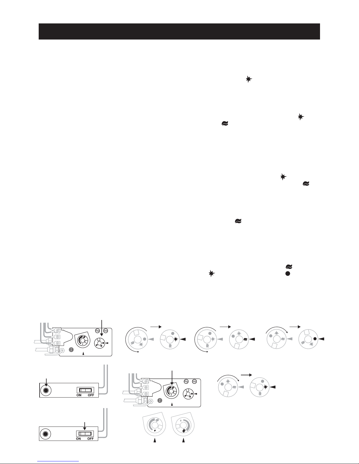
Lighting Instructions
PILOT FLAME IGNITION
Locate control knob on right hand side of valve. Depress and turn
control knob (FIG 1) to the PILOT position (FIG 4). Depress
the control button and ignite with piezo ignitor (FIG 2) whilst
keeping control knob firmly depressed for 20 seconds. Check that
pilot stays lit. If it goes out repeat ignition procedure.
MAIN BURNER IGNITION
Depress and turn control knob anti-clockwise from PILOT
position to the ON position (FIG 5). The burner will not
ignite if the rocker switch is depressed in the OFF position (FIG 3).
To light main burner press rocker switch to ON position (FIG 3).
TO TURN MAIN BURNER OFF WITH PILOT
REMAINING BURNING
Depress rocker switch to OFF position. (FIG 3)
Main burner can also be turned off by the use of control knob.This
is done by turning control knob clockwise to PILOT position
(FIG 8). Control knob will need to be turned back to ON
position (FIG 5) to light main burner.
TO TURN MAIN BURNER OFF OR ON WITH
OPTIONAL WALL SWITCH
Pilot must be burning.
Control knob is in the ON position. (FIG 5)
Rocker switch is in the OFF position. (FIG 3)
Wall switch can now be activated.
Important! Wall switch can only be activated if rocker switch is in
off position.
TO TURN PILOT AND MAIN BURNER OFF
Depress and turn control knob clockwise from ON position
(FIG 5) or PILOT position (FIG 4) to the OFF position
(FIG 6).
TO TURN MAIN BURNER HIGHER OR LOWER
Turn high / low flame knob to obtain high or low fire (FIG 7).
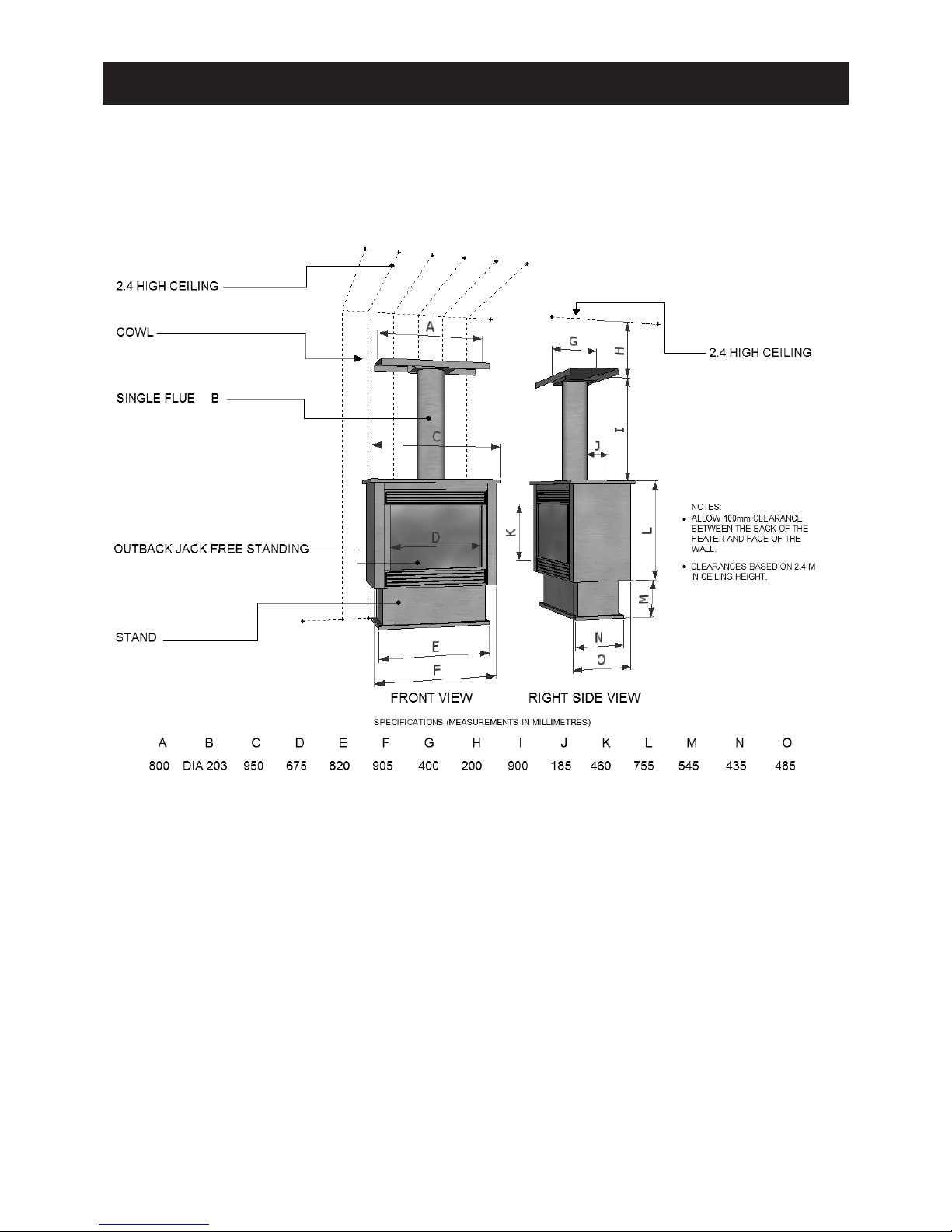
Installation Instructions for Jetmaster Outback Outdoor Patio Fire